Davis & Shirtliff Dayliff Installation instructions

MOBILE VACUUM CLEANER
Installation &
Operating Manual


INDEX
© Davis & Shirtliff Ltd 2020
Contents herein are not warranted
SPECIFICATIONS
1.
1
2.
INSTALLATION 3
3.2 Media Charging
2.2 Piping/Hose Connections
4
3
3.1 Use of Multiport Valve
2.1 Vaccuuming Your Pool
3
3
5. TROUBLE SHOOTING 7
6. TERMS OF WARRANTY 8
3. OPERATION 3
3.3 MPV Operation 4
3.4 Commissioning 6
3.5 Vacuuming Process 6
4. MAINTENANCE
6
7. DECLARATION OF CONFORMITY 8

1
1. SPECIFICATIONS
Congratulations on selecting a Dayliff Mobile Vacuum Cleaner System.
They are manufactured to the highest standards and if installed and
operated correctly will give many years of efcient and trouble free
service. Careful reading of this Installation Manual is therefore
important, though should there be any queries they should be
referred to the equipment supplier.
The Dayliff mobile cleaner is a manual pool cleaner with particular application in heavy
duty pool cleaning.
It comprises DPL 750 pump connected to DX300 filter mounted on a movable trolley.
It is used in conjunction with floating hose, vacuum head and a handle which are provided
on request.
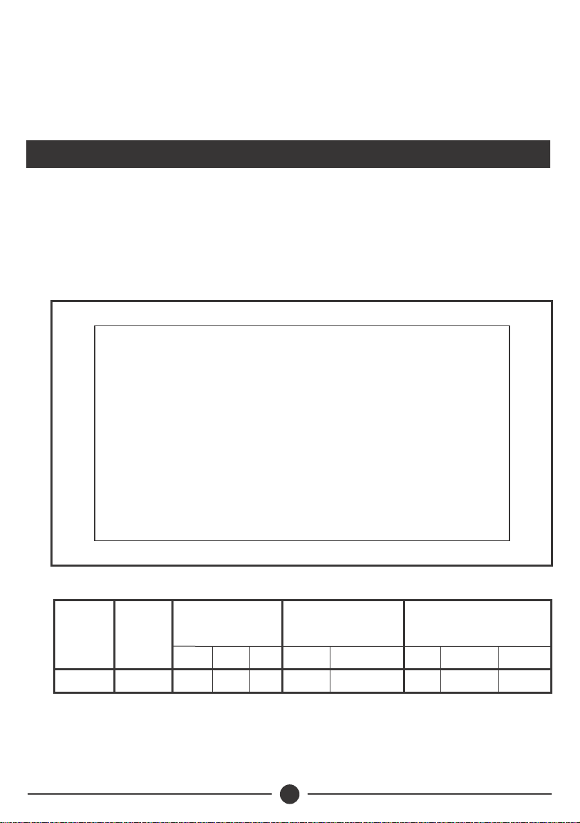
Fig. 1 Mobile Vacuum Cleaner Accessories
Filter
* Gross weight includes media and water
Model
Filter
Area
2
(m )
Dimension
(mm)
H
DX300 0.07 830 300 4.5 11
DLTest Net Gross Media
Working
Pressure
Bar
Weight
(kg)
3.0 115 50

2
The pipe connections must be correctly done as shown above.
Hand tightening is adequate for the MPV unions and under no
circumstances should a pipe wrench be used. If the union
weeps, add more thread tape on the union threads and make
sure to check that the union O-ring is in place.
WARNING
Model Speed
(RPM)
Power
(kW)
DPL 750
DPL Pump
2800 50 238
DN1/DN2 A
Dimensions (mm) Weight
(kg)
550 330 130.75
Current
(kW)
5.8
B D H
345
Multiport Valve
To waste
From pool
To pool

3
3. OPERATION
2. INSTALLATION
3.1 Use of Multiport valve
A typical multiport filter valve has six settings: Filter, Rinse, Recirculate, Backwash, Waste
and Closed. When vacuuming with the mobile vacuum cleaning unit, the choice of
settings depends upon the amount of dirt or other contamination in the pool. Routine
levels of particulates in a pool can usually be vacuumed with the multiport valve turned to
the Filter setting while directing the vacuumed water into the filter then back to the pool
through the return lines.
In some cases, it is not recommended to recirculate vacuumed water from the pool
through the sand filter. Where pool water is loaded with live algae or where dirt or dust has
infiltrated a covered, unused pool and formed a thick layer on the bottom, overloading
the filter with waste may clog the filter media. In addition, algae that has been “shocked”
and killed with a high dose of chlorine can pass through the sand filter media and re-enter
the pool. If flocculants have been used to clear the pool, it's advisable to vacuum to waste.
Particulates picked up by the vacuum are removed from the water by the bed of sand
filtration media inside the filter. Because vacuuming may deposit a concentrated amount
of dirt and other particulates in the sand filter media, it is advised to backwash the filter
after vacuuming.
2.1 Vacuuming the pool
Part of routine maintenance of a swimming pool includes vacuuming which involves
cleaning debris that has settled onto the pool floor. In some instances, flocculant is used to
clear suspended water clouding particles by forcing them to quickly settle onto the floor.
Depending on the condition of the pool, a choice can be made to either vacuum to waste
or to recirculate the filtered water back to the pool. With the former, water must be added
to restore the proper level in the pool and in turn, this addition of fresh water necessitates
testing and correcting the chlorine and pH balance in the pool.
2.2 Piping/Hose Connections
• Connect the vacuum hose to the suction end of the pool pump via an appropriate hose
connector.
• Connect the second hose to either the outlet pipe provided on the vacuum cleaner or
the waste end of the multiport valve of the DX300 filter.
• Prime the suction vacuum hose line by completely filling it with water. This can be done
by filling up water in the suction vacuum line via the pump basket with the hose inside
the pool and the opposite end raised slightly above water level.
• Secure the hose and the aluminum handle to the vacuum head and submerge the
vacuum head such that it rests on the pool floor.
• Set the multi-port valve on the DX300 filter to either filter or waste depending on the
condition of the pool.

4
Fig. 2 Media Filter
Layer 2 - Grade A - 0.6 bag
Layer 1 - Grade C - 0.3 bag
When charging proceed as follows:-
• Disconnect the inlet, outlet and backwash pipes from the Multiport Valve at the union
connectors.
• Unscrew and remove the Multiport Valve clamp and lift out the valve, which is sleeved
on to an extension from the bottom collector pipes. This pipe should now be blocked
with paper or a cloth to prevent the ingress of media during charging.
• Charge with media as per the instructions given above.
• Replace the Multiport Valve ensuring that both the valve neck and collector O-rings
have first been smeared with petroleum jelly. Note this should be done whenever the
Multiport Valve is removed. It is also important to ensure beforehand that all sand has
been removed from the filter O-ring seat and the O-ring itself to prevent leakage.
• Rotate the Multiport Valve to align the outlet ports with the piping and ensure proper
seating. When properly seated the clamp should be secured ensuring even but not over
tightening of the clamp bolts. If the joint weeps under pressure, reseat the MPV in a
different position ensuring it is properly seated on the filter neck. Over tightening will
damage the filter.
3.3 MPV Operation
DAYLIFF filters are fitted with a Multiport Valve to control filter operation. There are six
positions on the valve and the various operations possible with the different settings are
described below.
3.2 Media Charging
Media FilterThe filter is provided with suitably graded media which should be poured into
the filter as per the details given below
3 3
*Each standard DAYLIFF media bag is 1ft (0.03m ) & weighs appox. 50 kgs

5
RINSE
BACKWASH During normal operation the filter will accumulate dirt in
the media bed. This is cleaned by a process of
backwashing when the filter flow is reversed and water is
pumped from the bottom to the top of the filter and then
to waste. It should be carried out whenever the filter
pressure exceeds the clean running pressure by 0.3Bar,
there is a noticeable reduction in inlet flow or weekly,
whichever is the sooner. The backwashing process
normally takes 2-3 minutes and should be continued
until the waste water is observed as clean.
After backwashing the filter media needs to be rinsed.
Water is pumped into the top and out of the bottom of
the filter as for normal filtering, but it is then discharged
to waste. This removes any residual dirt in the media
instead of returning it to the pool. Rinsing should not
take more than one minute and again the sight glass on
the side of the valve can be used to see when the water is
clear.
RECIRCULATE In this position the filter is by-passed and the water is
pumped straight to the delivery point. It will normally
only be necessary to use this position if there is a
problem with the filter itself (e.g. a leak or major
blockage). It can also be used to test the filtering
pressure drop by comparing normal filtering pressure
with recirculation pressure.
WASTE
FILTER
TO POOL
FROM POOL
PUMP
The normal operating position. Water from the pump is
fed into the top of the filter and after passing through the
media is collected at the bottom. It is then returned to the
pool through the inlet pipes.
FILTER
WASTE
FILTER
PUMP
TO POOL
FROM POOL
PUMP
WASTE
FILTER
TO POOL
FROM POOL
TO POOL
FROM POOL
WASTE
FILTER
PUMP
WASTE The waste position is used for bye-passing the filter to
waste. In swimming pool applications make sure that
the pump is not switched off once the operation has
began as there may be problems with priming when the
water level is below the pump. This position can also be
used for vacuuming to waste. This may be necessary if
there is a large amount of sediment on the floor of the
pool which would rapidly clog the filter in normal
operation.
TO POOL
FROM POOL
WASTE
FILTER
PUMP

6
CLOSED This shuts off all flow to the filter. In pool applications it is
most frequently used to isolate the filter when removing
the line strainer lid to clean the basket.
WASTE
FILTER
PUMP
FROM POOL
TO POOL
3.4 Commissioning
When commissioning, the following procedure must be followed ensure the MPV is
properly working:-
•Open all suction valves and ensure that the pump strainer is filled with water.
• Open any valve on the return side of the filter.
• Set Multiport Valve to 'BACKWASH' and start pump.
• Check flow at the backwash pipe and allow the pump to run until the backwash water
is observed as reasonably clean, a minimum of five minutes being recommended. This
step is essential as the filter media is not fully pre-washed and this procedure rinses the
new sand clean. Note that as the filter is initially empty it will take time to fill and there
will be a delay of a minute or two from when the pump is switched on to when flow is
observed.
• Stop pump and turn MPV to 'RINSE'.
• Start pump and allow media bed to rinse until waste water is observed as clean. Stop
pump and turn MPV to 'FILTER'.
• Start pump and allow system to operate until a steady flow is noticed at the pool inlets.
As the system is not primed it will take time for all air to be bled, so be prepared for a
delay of up to ten minutes before a steady flow is apparent.
3.5 Vacuuming process
•Plug in the mobile vacuum cleaners pump power supply cable to the socket provided.
• Switch ON the pump.
• With the hose and the handle firmly secured onto the vacuum head, gently use long
and slow sweeping strokes to vacuum the pool starting from the shallow end. Make
sure your strokes overlap slightly to avoid leaving any debris behind.
Under no circumstances should the position of the Multiport
Valve be changed when the pump is running. Always switch off
the pump first or serious equipment damage may result.
WARNING
4. MAINTENANCE
The Dayliff mobile vacuum cleaner needs no routine maintenance other than regular
backwashing. Over time, the media will progressively clog and become less effective. The
period will depend on usage. Ineffective media becomes apparent through reduced filter
efficiency and when this occurs, re-charging with new media will be required.

7
PROBLEM
FILTER
POSSIBLE CAUSE SOLUTION
Flow rate very high
Water coming out
not clear
5. TROUBLE SHOOTING
Regulate flow rate to optimal levels to
ensure adequate filtration time
Filter not working well Check that the media is still in good
working condition
Clogged sand filter Back wash the filter
Feed pump not working well
Low clean water
flow
Check that the pump performance has
not dropped drastically
Filter clogged Back wash the filter
System’s pipeline clogged Check that the pipeline is not clogged
and clean pipe if it's the case
Feed pump failed Repair or replace the pump
No water supply at
all Valve arrangement control Check the right valves have been closed
or opened for the right process operation
Filter clogged Backwash the filter
Feed pump failed Repair or replace the pump

6. TERMS OF WARRANTY
i) General Liability
ii) Standard Warranty
Ÿ• In lieu of any warranty, condition or liability implied by law, the liability of Dayliff
(hereafter called the Distributor) in respect of any defect or failure of equipment
supplied is limited to making good by replacement or repair (at the Distributor’s
discretion) defects which under proper use appear therein and arise solely from faulty
design, materials or workmanship within a specified period. This period commences
immediately after the equipment has been delivered to the customer and at its
termination all liability ceases. Also the warranty period will be assessed on the basis
of the date that the Distributor is informed of the failure.
ŸThis warranty applies solely to equipment supplied and no claim for consequential
damages, however arising, will be entertained. Also the warranty specifically excludes
defects caused by fair wear and tear, the effects of careless handling, lack of
maintenance, faulty installation, incompetence on the part of the equipment user, Acts
of God or any other cause beyond the Distributors's reasonable control. Also, any
repair or attempt at repair carried out by any other party invalidates all warranties.
If equipment failure occurs in the normal course of service having been competently
installed and when operating within its specified duty limits warranty will be provided as
follows:-
Ÿ Components making up the plant or system are covered individually under
the specic item’s warranty terms.
Ÿ Consumable e.g. cartridges are not covered by warranty.
The warranty on equipment supplied or installed by others is conditional upon the
defective unit being promptly returned free to a Davis & Shirtliff ofce and collected
thereafter when repaired. No element of site repair is included in the warranty and any site
attendance costs will be payable in full at standard charge out rates. Also proof of
purchase including the purchase invoice must be provided for a warranty claim to be
considered.
8

INS462A-09/20
www.davisandshirtliff.com
Other manuals for Dayliff
2
Table of contents