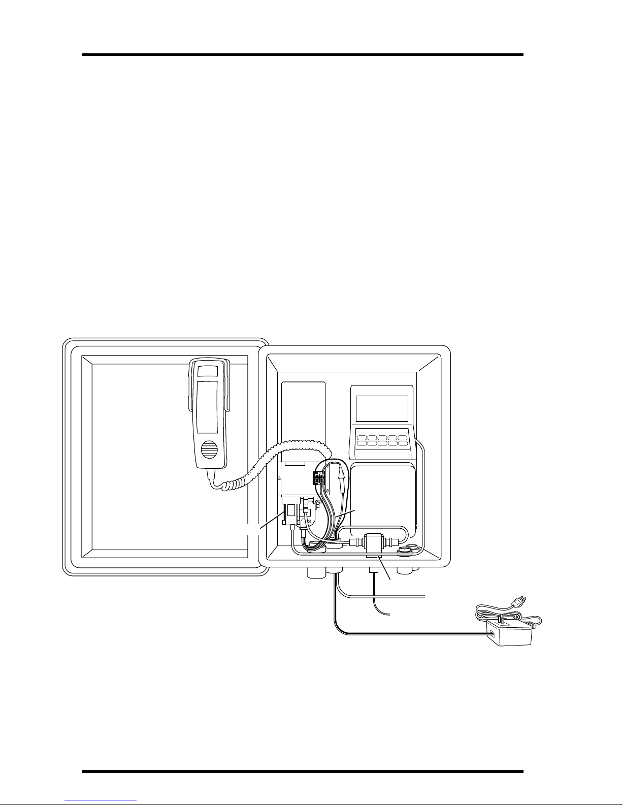
DAVIS CELLULAR TELEPHONE ANTENNA KIT User manual

Product#7652-003
C
ELLULAR
T
ELEPHONE
A
NTENNA
K
IT
I
NSTALLATION
M
ANUAL
I
NTRODUCTION
The Cellular Telephone Antenna Kit contains the materials necessary to con-
nect a WeatherLink
®
data logger to a Motorola SMCT2 cellular telephone
modem (CTM). The SMCT2 CTM must be obtained from Motorola. See the
accompanying sheet for Motorola contact information.
C
OMPONENTS
The Cellular TelephoneAntenna Kit includes the following components. Please
make sure you have all listed components before continuing.
✦
Antenna, 806-896 MHz 3dB, Omni-Directional
✦
Ground Plane, with antenna base, antenna cable with BNC connector
✦
Terminal Plate, with 4-position terminal block and adhesive foam tape
✦
WeatherLink Radio/SRModem Adapter
✦
WeatherLink PC Radio Adapter
CTM Power
Cable
Power Connector
Brackets
Ground Plane &
Antenna Cable
#8 x 3/4" Machine Screws,
Washers, Lock Washers, & Nuts
2-Amp Power
Adapter
Modular Cable
AOM Wires
Jumper
Terminal
Plate Terminal
Block
BNC Adapter
Antenna
WeatherLink
Radio/SR Modem
Adapter
WeatherLink
PC Radio
Adapter
Modem RF
Cable Modem
Configuration
Disk
Tab Adapter
Battery Wires
#6 Sheet Metal Screws
#4 Machine Screws, Washers,
Star Washers, & Nuts
10 A Fuse

Page2 CellularTelephoneAntennaKit
✦
BNC Adapter
✦
Power Adapter, 12V, 2A
✦
Modem RF Cable, co-axial, BNC and Mini-UHF connectors, 12" (30 cm) long
✦
CTM Power Cable, DB25 connector and cable
✦
Modular Cable, 6-conductor, 4' (1.2m) long
✦
Two Tab Adapters
✦
Two Battery Wires (1 red, with in-line fuse holder, 1 black)
✦
Three Alarm Output Module Wires (1 green, 1 yellow, 1 white)
✦
Jumper Wire, yellow
✦
Three #6 Sheet Metal Screws (for mounting modem bracket)
✦
Two #8-32 x 3/4" Machine Screws, Washers, Lock Washers, and Nuts (for mount-
ing antenna)
✦
Two Power Connector Brackets and #6 Screws
✦
Two #4 x 3/8" Machine Screws and Two #4 x 3/4" Machine Screws, Washers, Star
Washers, and Nuts (for mounting hang-up cup)
✦
Four #4 x 3/8" Machine Screws and Nuts (for mounting Timer on terminal plate)
✦
Modem Configuration Disk
Motorola SMCT2 Cellular Telephone Modem Components
The Motorola SMCT2 CTM should include the following components, which
will be necessary for the installation.
✦
Cellular telephone Modem (S5692A)
✦
Mounting Bracket
✦
4 Adhesive Pads
The CTM should also include a power cable, two wire/fuse loops, one black
wire, and a hardware package, none of which is needed.
Mounting Bracket
and Adhesive Pads
Cellular Telephone
Modem

Components Page3
Power Components
You will need to supply power to the CTM site, using one of the following
options.
✦
If AC power is available at the CTM site, use the power adapter supplied with this
kit.
✦
To power the CTM with solar power, use the Solar Power Kit (#7708) and 6.5-
Amp-Hour Battery (#7711).
If solar power is used, it will be necessary to switch the power to the
phone so that it is on for only limited periods in order to conserve the
power drawn. Two alternatives are available:
✦
Alarm Output Module (#7736)
✦
Timer (#7682)
The Timer is recommended unless the Alarm Output Module is
being used for other purposes.
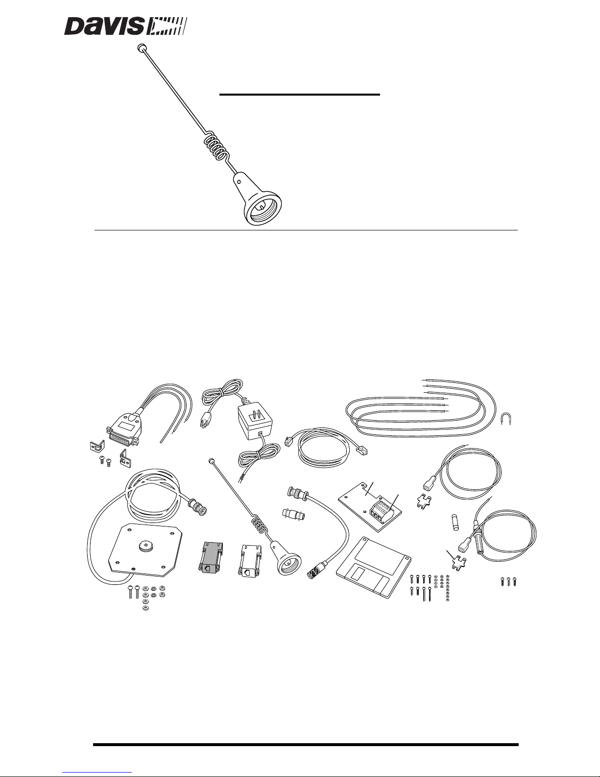
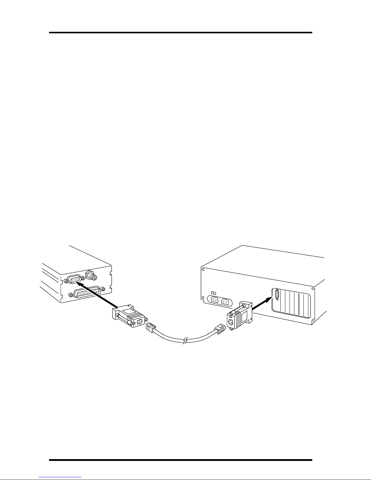
WeatherLink Components
You will need the following item from your WeatherLink package:
✦
PC COM Port Adapter
On older versions of the WeatherLink, this adapter was labelled AT
Adapter.
Optional Components
The following optional components may be necessary for your installation.
✦
Radio Surge Protector (#7681SSC)
If the CTM is located in an area where lightning strikes are a possibility,
use the Radio Surge Protector to provide surge protection between the
antenna and the CTM. Davis recommends the use of the Radio Surge
Protector in
all installations
.
✦
Antenna Mounting Bracket (#7684)
The hardware provided with the Antenna Kit enables you to mount the
antenna on the Sensor Mounting Arm (#7702). If you want to mount it
on a pole, post, or wall, use the Antenna Mounting Bracket.
Note:
The CTM’s antenna should be located as high as possible and away from buildings and
other obstructions, if possible. It is best if the path between the antenna and the near-
est phone company cell antenna is completely unobstructed (line-of-sight). Intervening
trees and other vegetation can reduce the signal intensity.
✦
Handset (Motorola #SL2504) and Hang-Up Cup Assembly (Motorola #SL9854)
If you wish to originate or receive voice calls at the weather station/
CTM site, you will need to order the handset and hang-up cup assembly
from Motorola. Consult the Motorola Contact and Parts Information
Sheet for more details.

Page4 CellularTelephoneAntennaKit
T
OOLS
R
EQUIRED
In addition to the components listed above, you may need the following tools.
Please be sure you have everything you need before beginning the installation.
✦
Phillips Screw Driver
✦
Slotted Screw Driver
✦
Electric Drill with 7/32" (5.5 mm) and 1/8" (3 mm) drill bits
T
YPICAL
I
NSTALLATIONS
The illustrations below show three typical installations: AC-powered, solar-
powered using the Timer, and solar-powered using theAlarm Output Module.
A list of steps for each installation type is provided.
AC-Powered
The illustration below shows an AC-powered station and cellular telephone
modem (CTM).
You must complete the following steps for this installation.
1. Configure the CTM (see “Configuring The Cellular Telephone Modem” on page 8).
2. Install antenna (see “Installing Antenna” on page 11).
3. Install Radio Surge Protector (optional).
Consult the manual supplied with the Radio Protector for installation
instructions.
Cell Phone
Handset Console
Sensor
Interface
Module
Terminal
Block
CTM Power
Cable
Radio Surge Protector (optional)
To Antenna
Protector Ground
CTM
Link Adapter
+12 V AC-Power
Ada
p
ter

TypicalInstallations Page5
4. Install CTM (see “Installing Cellular Telephone Modem” on page 13).
5. Install terminal plate (see “Installing Terminal Plate/Timer” on page 15).
6. Connect AC-power wires (see “Connecting AC-Power Wires” on page 16).
Do not connect to AC power yet.
7. Install hand set and hang-up cups (optional; see “Installing Handset and Hang-Up
Cups” on page 20).
If you wish to originate or receive voice calls at the weather station/CTM
site, you will need to install the handset and hang-up cup assembly.
8. Check wiring.
Before you apply power to the system, review your wiring to make sure all
connections are correct and all wires firmly secured in the proper terminal.
9. Connect power to system.
Do not connect power until the rest of your installation is complete.
Plug the
power adapter into a power outlet.
10.Finalize the installation by testing the installation (see “Finalizing the Installation” on
page 21).
Solar-Powered Using Timer
The illustration below shows a solar-powered station and CTM using a Timer
for power conservation.
You must complete the following steps for this installation.
Cell Phone
Handset
Regulator
In-Line
Fuses
Battery
Console
Sensor
Interface
Module
Terminal
Block
CTM Power
Cable
Radio Surge Protector (optional)
To Antenna
Protector Ground
CTM
Timer
Link Adapter

Page6 CellularTelephoneAntennaKit
1. Configure the CTM (see “Configuring The Cellular Telephone Modem” on page 8).
2. Install antenna (see “Installing Antenna” on page 11).
3. Install Solar Power Kit and 6.5-Amp-Hour Battery (see “Installing Solar Power Kit &
Battery” on page 12).
4. Install Radio Surge Protector (optional).
Consult the manual supplied with the Radio Protector for installation
instructions.
5. Install CTM (see “Installing Cellular Telephone Modem” on page 13).
6. Install terminal plate and Timer (see “Installing Terminal Plate/Timer” on page 15).
7. Connect Timer and battery wires (see “Connecting Timer and Battery Wires” on
page 17).
8. Install hand set and hang-up cups (optional; see “Installing Handset and Hang-Up
Cups” on page 20).
If you wish to originate or receive voice calls at the weather station/CTM
site, you will need to install the handset and hang-up cup assembly.
9. Check wiring.
Before you apply power to the system, review your wiring to make sure all
connections are correct and all wires firmly secured in the proper terminal.
10.Connect power to system.
Do not connect power until the rest of your installation is complete.
Connect the
battery cable to B2 on the regulator circuit. Connect the solar panel cable to
B1 on the regulator circuit. Finally, insert the fuse into the in-line fuse holder
in the red battery wire.
11. Finalize the installation by programming the Timer and testing the system (see “Final-
izing the Installation” on page 21).

TypicalInstallations Page7
Solar-Powered Using Alarm Output Module
The illustration below shows a solar-powered station and CTM using the
Alarm Output Module (AOM) for power conservation.
You must complete the following steps for this installation.
1. Configure the CTM (see “Configuring The Cellular Telephone Modem” on page 8).
2. Install antenna (see “Installing Antenna” on page 11).
3. Install Solar Power Kit and 6.5-Amp-Hour Battery (see “Installing Solar Power Kit &
Battery” on page 12).
4. Install Alarm Output Module.
Consult the manual supplied with the AOM for instructions. Make sure to
mount the AOM in the location shown above.
5. Install Radio Surge Protector (optional).
Consult the manual supplied with the Radio Protector for installation
instructions.
6. Install CTM (see “Installing Cellular Telephone Modem” on page 13).
7. Install terminal plate (see “Installing Terminal Plate/Timer” on page 15).
8. Connect Alarm Output Module and battery wires (see “Connecting Alarm Output Mod-
ule and Battery Wires” on page 19).
Sensor
Interface
Module
Cell Phone
Handset
Regulator
In-Line
Fuses
Battery
Console
Terminal
Block
CTM Power
Cable
Radio Surge Protector (optional)
To Antenna
Protector Ground
CTM
Link Adapter
Alarm Output
Module (AOM)

Page8 CellularTelephoneAntennaKit
9. Install hand set and hang-up cups (optional; see “Installing Handset and Hang-Up
Cups” on page 20).
If you wish to originate or receive voice calls at the weather station/CTM
site, you will need to install the handset and hang-up cup assembly.
10.Check wiring.
Before you apply power to the system, review your wiring to make sure all
connections are correct and all wires firmly secured in the proper terminal.
11. Connect power to system.
Do not connect power until the rest of your installation is complete.
Connect the
battery cable to B2 on the regulator circuit. Connect the solar panel cable to
B1 on the regulator circuit. Finally, insert the fuse into the in-line fuse holder
in the red battery wire.
12. Finalize the installation by programming the AOM and testing the installation (see
“Finalizing the Installation” on page 21).
C
ONFIGURING
T
HE
C
ELLULAR
T
ELEPHONE
M
ODEM
As delivered by Motorola, the cellular telephone modem (CTM) is not compati-
ble with your WeatherLink. Follow the instructions below to configure the CTM.
Connect the CTM to your Computer
Connect the CTM to your computer, as shown below.
1. Connect the PC COM Port Adapter to a serial port on your PC.
2. Connect one end of the modem cable to the PC COM Port Adapter.
3. Connect the PC RADIO Adapter to the DB9 connector on the CTM.
4. Connect the other end of the modem cable to the PC RADIO Adapter.
Modem
(CTM)
Modular
Cable
PC Com
Port
PC RADIO
Adapter
PC COM Port
Adapter

ConfiguringTheCellularTelephoneModem Page9
Power the CTM
Connect power to the CTM, as shown below.
1. On one side of the terminal block, connect the black CTM power wire to terminal 1
(grey), the green CTM power wire to terminal 3 (orange), and the red CTM power wire
to terminal 4 (orange).
2. On the other side of the terminal block, connect the black power adapter wire to ter-
minal 1 (grey) and the red power adapter wire to terminal 4 (orange).
3. Plug the power adapter into a power outlet.
Run The Modem Configuration Program
Finally, use the supplied modem configuration program to configure the CTM.
1. Place the Modem Configuration Disk in your disk drive.
2. Choose Run from the File Menu (Windows 3.1) or the Start Menu (Windows 95).
AC-Power
Adapter Wires
+
_
Terminal
Block
1234
RedBlack
Green
Modem
(CTM)
CTM Power
Cable
(PCRADIOAdapter
NotShown)

Page10 CellularTelephoneAntennaKit
3. Type A:\CONFIG and press Enter (or choose Ok).
The Wireless Configuration Program dialog box appears.
4. Select Cell Phone Modem from the Modem Type drop-down list.
5. Select the COM port to which the CTM is connected from the COM Port drop-down list.
If you don‘t know the COM port number, choose COM 1. If you get a pro-
gram error when attempting to configure the CTM, try again using COM 2,
and so on, until you find the correct COM port setting.
6. If you fully understand the CTM’s AT command set and wish to configure the CTM dif-
ferently than the default configuration, choose Advanced. You may then enter the
desired AT commands and choose Execute Command to execute the string. Choose
View Conf to view the CTM’s current configuration.
The default configuration should work in almost all installations; we do not
recommend using the Advanced setting option.
7. When finished, choose Configure.
The program will attempt to locate and configure your CTM. If you encoun-
ter an error, make sure you have selected Cell Phone Modem and then try
different serial ports until the configuration completes successfully.

Installation Page11
I
NSTALLATION
Follow the instructions below to install the various components of your CTM.
In many cases, you will need to use the installation manual supplied with the
component for specific instructions.
Note:
Before beginning the installation, disconnect the cables attached in order to configure the CTM.
Installing Antenna
You may mount the antenna on either the Sensor Mounting Arm or on a pipe,
post, or wall using the Antenna Mounting Bracket (#7684).
✦
Installing on Sensor Mounting Arm (SMA)
Attach the antenna to the ground plane as shown below; screw on until
snug. Attach the ground plane to the SMAusing the #8-32 x
¾
" screws,
flat washers, split lock washers, and hex nuts as shown below.
Note:
It may be necessary to drill one or two holes in the SMA to accommodate the antenna/
ground plane assembly. If so, use the holes in the ground plane as a guide and drill holes
using a 7/32" (5.5mm) drill bit.
Ifnecessary,drillholesusing
7/32"(5.5mm)drillbit.
Antenna
Ground
Plane
8-32 x 3/4" Screw
Flat Washer
Flat Washer
Lock Washer
#8 Hex Nut
Ground Plane
Sensor Mounting Arm

Page12 CellularTelephoneAntennaKit
✦
Installing on Pipe, Post, or Wall
Mount the Antenna Mounting Bracket (AMB) on the pipe, post, or wall
according to the instructions supplied with the bracket. Attach the
antenna to the ground plane as shown below; screw on until snug.
Attach the ground plane to the AMB using the #8-32 x
¾
" screws, flat
washers, split lock washers, and hex nuts as shown below.
Installing Solar Power Kit & Battery
Consult the manuals supplied with the appropriate component for instruc-
tions. Note the following, however, as you proceed with the installation.
✦
Use tab adapters to attach wires to the battery.
Before installing the battery, slide the tab adapters onto the terminals.
Attach the black battery wire (supplied with this kit) and the black wire
from the battery cable (supplied with the Solar Power Kit) to the tab
adapter connected to the ground (black) terminal. Attach the red battery
wire (suppplied with this kit) and the red wire from the battery cable
(supplied with the Solar Power Kit) to the tab adapter connected to the
positive (red) terminal. Make sure you have access to the free end of the
battery wires and the battery cable once the battery is installed.
✦
Do not connect the solar panel or the battery to the regulator circuit.
Make sure you have made no connections at B1 and B2 on the regulator
circuit before proceeding.
Antenna
Ground
Plane
8-32 ¥ 3/4" Screw
Flat Washer
Flat Washer
Split LockWasher
#8 Hex Nut
Antenna Mounting
Bracket Lag Screws
(to mount on pipe,
use 11/2" U-bolts and
1/4" nuts & washers)

Installation Page13
Installing Cellular Telephone Modem
Follow the instructions below to install the cellular telephone modem (CTM).
Install the station console/WeatherLink prior to installing the modem.
1. Connect the power cable to the DB-25 connector on the CTM, as shown below.
2. Connect the WeatherLink Radio/SRModem Adapter to the DB-9 connector on the CTM.
3. Connect one end of the modem RF cable to the mini-UHF connector on the CTM.
4. Apply adhesive pads to the bracket according to the instructions supplied with the
CTM.
5. Attach the CTM and mounting bracket to the back of the Complete System Shelter or
the wall of a shed or other housing using the #6 sheet metal screws, as shown
below.
Power
Connector
Brackets 3/8" #6 Screws
Complete System Shelter
Back Panel
(or shed wall)
Modem
(CTM)
Mounting
Bracket

Page14 CellularTelephoneAntennaKit
6. Connect the WeatherLink cable to the L1 connector on the WeatherLink Radio/SRMo-
dem Adapter.
7. Connect the free end of the modem RF cable to the BNC adapter or the EQUIPMENT
side of the Radio Surge Protector.
8. Connect the antenna cable to the BNC adapter or the ANTENNA side of the Radio
Surge Protector (routing the antenna cable through one of the strain reliefs at the
bottom of the shelter, if using the shelter).
Modem
(CTM) WeatherLink
Data Logger
Console Base
BNC Adapter
OR
Surge
Protector
(optional)
Modem RF
Cable Antenna
Cable
From WeatherLink
WeatherLink
Radio/SR Modem
Adapter

Installation Page15
Installing Terminal Plate/Timer
If using the Timer, attach it to the terminal plate as shown below. Secure the ter-
minal plate to the mounting bracket using the adhesive tape on the back of the
plate, as shown below.
Timer (if used)
Terminal Plate
Adhesive
Foam Tape
Mounting
Bracket

Page16 CellularTelephoneAntennaKit
Connecting AC-Power Wires
Connect the CTM power cable and AC-power adapter to the terminal block, as
shown below.
✦On one side of the terminal block, connect the black CTM power wire to terminal 1
(grey), the green CTM power wire to terminal 3 (orange), and the red CTM power
wire to terminal 4 (orange).
✦On the other side of the CTM, connect the black wire from the power adapter or to
terminal 1 (grey) and the red wire to terminal 4 (orange).
CTM
Terminal
Block
Red
Black Green
1234
CTM Power
Cable
Red (+)
Black (-)

Installation Page17
Connecting Timer and Battery Wires
If using solar power in conjunction with the Timer, connect the system as
shown below.
✦On one side of the terminal block, connect the black battery wire to terminal 1
(grey), the red/white Timer wire to terminal 2 (green), and the red battery wire to
terminal 4 (orange).
Modem
Terminal
Block
RedBlack
RedBlack
Green
1234
CTM Power
Cable
Power-Conserving
(operating) Position
Power-Up & Test
Position
Timer
5321
Red/Wht
Wht Blk
Regulator B3
B4
P1
B2
B1
Yel
Grn
Wht
Blk
Wht
Blk
Battery Cable
Supplied with
Solar Power Kit Battery
Blk
Blk Red
Red
Tab Adapters
In-Line
Fuse
_
+

Page18 CellularTelephoneAntennaKit
✦On the other side of the terminal block, connect the black CTM power wire to ter-
minal 1 (grey), the green CTM power wire to terminal 3 (orange), and the red CTM
power wire to terminal 4 (orange).
The green wire will need to be moved to terminal 2 (green) after you
have tested the installation. Connecting the wire to terminal 3 bypasses
the “power-saver” mode and insures power is applied simultaneously to
the red and green CTM power wires.
✦Connect the white and black wires from the Timer to the Wht and Blk terminals
(respectively) at B4 on the regulator circuit.
✦Jumper together the two terminals (Yel and Grn) at B3 on the regulator circuit
using the jumper wire.

Installation Page19
Connecting Alarm Output Module and Battery Wires
If using solar power in conjunction with the Alarm Output Module (AOM),
connect the system as shown below.
✦On one side of the terminal block, connect the black battery wire to terminal 1
(grey), the red/white Timer wire to terminal 2 (green), and the red battery wire to
terminal 4 (orange).
Modem
Terminal
Block
RedBlack
RedBlack
Green
1234
CTM Power
Cable
Power-Conserving
(operating) Position
Power-Up & Test
Position
Regulator B3
B4
P1
B2
B1
Yel
Grn
Wht
Blk
Wht
Blk
Battery Cable
Supplied with
Solar Power Kit Battery
Blk
Blk Red
Red
Tab Adapters
In-Line
Fuse
_
+
Wht
Wht
Yel
Grn
Alarm Output
Module
+
_
B
Contacts

Page20 CellularTelephoneAntennaKit
✦On the other side of the terminal block, connect the black CTM power wire to ter-
minal 1 (grey), the green CTM power wire to terminal 3 (orange), and the red CTM
power wire to terminal 4 (orange).
The green wire will need to be moved to terminal 2 (green) after you
have tested the installation. Connecting the wire to terminal 3 bypasses
the “power-saver” mode and insures power is applied simultaneously to
the red and green CTM power wires.
✦Connect one end of the yellow AOM wire to the Yel terminal at B3 on the regulator
circuit. Connect the other end to the positive (+) terminal at B on the AOM.
✦Connect one end of the green AOM wire to the Grn terminal at B3 on the regulator
circuit. Connect the other end to the negative (-) terminal at B on the AOM.
✦Connect one end of the white AOM wire to the Wht terminal at B4 on the regula-
tor circuit. Connect the other end to terminal 2 (green) on the terminal block, on
the same side as the power wires.
Installing Handset and Hang-Up Cups
If you wish to originate or receive voice calls at the weather station/CTM site,
install the handset and hang-up cup as shown below.
Note:If you install a handset you must not turn power off at the handset when leaving the station
because this overrides the Timer or Alarm Output Module control. The handset power must be
on for the “power saver” switching to “wake up” and receive calls from the WeatherLink soft-
ware.
✦Installing the Handset
Insert the phone plug on the end of the handset cable into the jack on the
side of the CTM.
✦Installing the Hang-Up Cups in Complete System Shelter (CSS)
Use the cup as a guide and drill holes in the upper right corner of the CSS
door with a ⅛" (3 mm) drill bit. Secure the cup using the #4 screws,
washers, star washers, and nuts as show below. Use the #4 x ¾" screws in
the two lower holes and the #4 x ⅜" screws in the two upper holes. Make
sure the cup is oriented correctly, with the white bumper at the top.
#4 x 3/4" Screw
and Washer
(2 lower holes) Hang-Up
Cup
#4 Star Lock
Washer and Nut
#4 x 3/8" Screw
and Washer
(2 upper holes)
Table of contents
Other DAVIS Antenna manuals
Popular Antenna manuals by other brands

Buffalo
Buffalo AirStation WLE-HG-NDR Specifications

TRENDnet
TRENDnet TEW-AO08O Quick installation guide

Channel Master
Channel Master 75cm Elliptical Triple-Beam Instruction and assembly manual

Aerohive
Aerohive AP170 installation guide

Honeywell Home
Honeywell Home AlarmNet CELL-ANTST Installation and setup guide

Choice Select
Choice Select CHO5007 Information sheet