DaytonAudio Epique CBT36K User manual

CBT36K Assembly Manual
Constant Beamwidth Transducer System
Signature Series

CBT36K Assembly Manual
PREFACE:
This is the assembly/instruction manual for the CBT36K, a DIY kit-version
of the CBT36 system,a floor-standing CBT circular-arc high-end
loudspeaker line array. The system is sold as a do-it-yourself
(DIY) loudspeaker kit by Dayton Audio. The system is also available as
a completed unit. The CBT36 is a floor-standing 5 ft. tall two-way
curved line array that provides sonic accuracy, low distortion, and sound
field coverage control surpassing even the finest high-end loudspeakers.
One additional amazing feature of the CBT36 is that it is time aligned
and linear phase not only at a “magic listening spot” in front of the array
but at locations on the floor, to locations above the array, and
locations at extreme off-axis horizontal angles!
The CBT36 is based upon declassified military research on
uniform-coverage underwater sound transducers originated by the US
Navy in the late 70s and early 80s. CBT, which stands for
Constant Beamwidth Transducer, is a term coined by the military
researchers in their technical papers.The system is designed by
Marshall Kay and Don Keele.
Each array features 18 Dayton Audio 3.5" ND Series drivers along with
72 specially designed 1/2" aluminum dome tweeters, and is available
in kit form as well as afully assembled product. The CBT36 will
redefine your expectations of audio reproduction system performance!
Page 2 of 89

CBT36K Assembly Manual
Page 3of 89
CONTENTS AT A GLANCE:
CBT36K ASSEMBLY MANUAL...................................................1
PREFACE:....................................................................................2
CONTENTS:...............................................................................3-4
1. THE PRELIMINARIES: ...................................................... 5-7
1.1. OVERVIEW OFTHIS MANUAL AND THE ASSEMBLY PROCESS:...........................................................5-6
1.2. MASTER CHECKLIST:.....................................................................................................................6,7
1.4. WORK AREA:...................................................................................................................................7
1.5. SAFETY FIRST:................................................................................................................................ 7
2. WHAT’S NEEDED? .........................................................8-11
2.1. TOOLS AND CONSUMABLES NEEDED:...............................................................................................8
2.2. AUDIO MEASUREMENT TOOLS:................................................................................................ 9,10,11
3. WHAT’S HERE? ............................................................12-15
3.1. MATERIAL INVENTORY LIST:............................................................................................12,13,14,15
4. CABINET FINISHING: ...................................................16-17
4.1. FINISHING THE CABINET:................................................................................................................16
4.2. SELECT PAINTING SYSTEM:............................................................................................................16
4.3. CABINET FINISHING: .......................................................................................................................17
4.4. FRONT PANEL FINISHING: ...............................................................................................................17
5. TESTING AND PREPARATION OF WIRES,
COMPONENTS, AND RESISTORS:.....................................18
-
25
5.1. TEST ALL MID-BASS DRIVERS AND TWEETER MODULES:.............................................................18-19
5.2. PREPARE THE RESISTORS: .......................................................................................................19-20
5.3. CONFIGURE AND TRIM THE RESISTOR LEADS:.............................................................................20-21
5.4. PREPARE ALL REQUIRED WIRE LENGTHS:..............................................................................21,22,23
5.5. CUT WIRE TO LENGTH AND REMOVE INSULATION:............................................................................24
5.6. ATTACH WIRES TORESISTORS: ................................................................................................24,25
5.7. ATTACH LEAD WIRES TOSPEAKON CONNECTOR: ...........................................................................25
6. MOUNT DRIVERS ON FRONTPANEL..........................26-32
6.1. PREPARE PAINTED FRONT PANELS FOR DRIVERS:................................................................26,27,28
6.2. PARTS AND TOOLS FOR DRIVER INSTALLATION:...............................................................................28
6.3. MOUNT TWEETER MODULES TOFRONT PANEL:....................................................................28,29,30
6.4. MOUNT ND-91MID-BASS DRIVERS TO FRONT PANEL:..........................................................30,31,32
7. DRIVER WIRING:...........................................................33-45
7.1. MID-BASS SHADING-NETWORK SCHEMATIC:...............................................................................33-34
7.2. MID-BASS SHADING BANK WIRING DIAGRAMS AND ASSEMBLY STEPS:.................... 34,35,36,37,38,39
7.3. TWEETER MODULE SHADING-NETWORK SCHEMATIC:..................................................................40,41
7.4. TWEETER-MODULE SHADING BANK WIRING DIAGRAMS AND ASSEMBLY STEPS:...........41,42,43,44,45
8. SOLDER CONNECTIONS, DRESS THE WIRING, AND
MOUNT RESISTORS:...........................................................46-48
8.1. FINAL WIRING CHECK:...................................................................................................................46
8.2. SOLDER LEADS TOMID-BASS DRIVERS AND TWEETER MODULES:..............................................46-47
8.3. GLUE RESISTORS TO BACKS OF MID-BASS DRIVERS:.................................................................47-48
8.4. DRESS WIRING FOR ND91 MID-BASS DRIVERS AND TWEETERS:.....................................................48
9. TEST THE WIRING:.......................................................49-51
9.1. VERIFY CORRECT POLARITY OF DRIVERS MOUNTED TOFRONT PANEL:.......................................49,50
9.2. VERIFY SHADING BANK ATTENUATIONS:.....................................................................................50,51

CBT36K Assembly Manual
Page 4of 89
10. ASSEMBLE THE CABINET: .........................................52-55
10.1. INSTALL SPEAKON CONNECTOR ON REAR OF CABINET:...................................................................52
10.2. LOAD ACOUSTIC FILLER IN CABINET:..............................................................................................52
10.3. GASKET INSTALLATION:..................................................................................................................53
10.4.DIAGRAM OFBASE ASSEMBLY:.......................................................................................................54
10.5.
10.6.
11. MORE TESTING: ...........................................................56-57
11.1. VERIFY SPEAKON WIRING:.............................................................................................................56
11.2. RATTLE AND BUZZ TESTS: ........................................................................................................56,57
11.3. CONGRATULATIONS,THE ASSEMBLY OF THE CBT36K IS COMPLETE!!!!............................................57
12. CROSSOVER SETUP:...................................................58-70
12.1. SETUP OF BEHRINGER DCX2496 ULTRADRIVE PRO DSP CROSSOVER:.....................................58-67
12.2. CONNECT THE BEHRINGER DCX2496 CROSSOVER TO THE SYSTEM: ..............................................68
12.3. CROSSOVER FILTER/EQ SETTINGS TABLE:................................................................................ 69-70
13. STARTING UP YOUR SYSTEM.....................................71-72
13.1. TURN ON THE SYSTEM:..................................................................................................................71
13.2. SYSTEM CONNECTIONS:EXAMPLE OF A MODERN-DAY HIGH-END AUDIO SYSTEM:...........................72
14. APPENDICES: ...............................................................73-87
14.1. APPENDIX 1: DETAILED DESCRIPTION OFTHE CBT36: ..............................................................73-80
14.2. APPENDIX 2: CBT THEORY OFOPERATION:...............................................................................81-87
15. CBT36 FRONT-PANEL WIRING FOLDOUT......................88
ATTACH FRONT PANEL TOCABINET:...............................................................................................55
CONNECT WIRES FROM MID-BASS AND TWEETER TOSPEAKON WIRES:............................................55

CBT36K Assembly Manual
1. THE PRELIMINARIES:
INTRODUCING the CBT36:
The CBT36 is a floor-standing
5ft.-tall two-way curved line
array that provides sonic
accuracy and sound-field
coverage that surpasses even
the finest high-end
loudspeakers.
The system not only provides
extremely even coverage at all
points up-down, right-left, and
near-far; but is linear-phase
and time-aligned at all these
points also!
Based upon declassified
military research on Constant
Beamwidth Transducers
(CBT) originated bythe U.S.
Navy, and a series of technical
papers byDon Keele, the
system was designed by
Marshall Kay and Don Keele.
Each array features 18 Dayton
Audio 3.5” NDSeries drivers
with 72 specially designed ½”
aluminum-dome tweeters, and
is available assembled or in kit
form. The CBT36 will redefine
your expectations of audio
reproduction system
performance.
1.1. OVERVIEW OF THIS MANUAL AND THE ASSEMBLY PROCESS:
This manual describes the assembly process of the CBT36K curved-arc high-end loudspeaker array
sold by electronic supplier Parts Express. It includes many sections to aid in the assembly
procedure. Two appendices are provided at the end of this manual: the first gives a detailed
description of the CBT36 along with a set of specifications, and the second fully describes the theory of
operation behind CBT loudspeaker arrays and how it applies to the design of the CBT36 and includes a
CBT bibliography.
When you first view this manual for the CBT36K, the assembly process looks very imposing, complicated
and difficult! But first looks can be deceiving. We have done all we can to simplify the assembly process
by spelling out the procedure in great detail and documenting all steps with high-resolution photos to
guide you through the process.
Although the manual is quite large, it’s jam-packed with useful information. With the comprehensive
information provided in this manual, the CBT36 has to be the most documented high-end loudspeaker
that has ever been sold! There are absolutely no secrets here!
Page 5of 89

CBT36K Assembly Manual
This manual contains many sections and subsections which take you through the assembly process in
much detail. A master check list is provided along with check boxes in the individual sections of the
manual.
1.1.1. What Parts are Supplied?
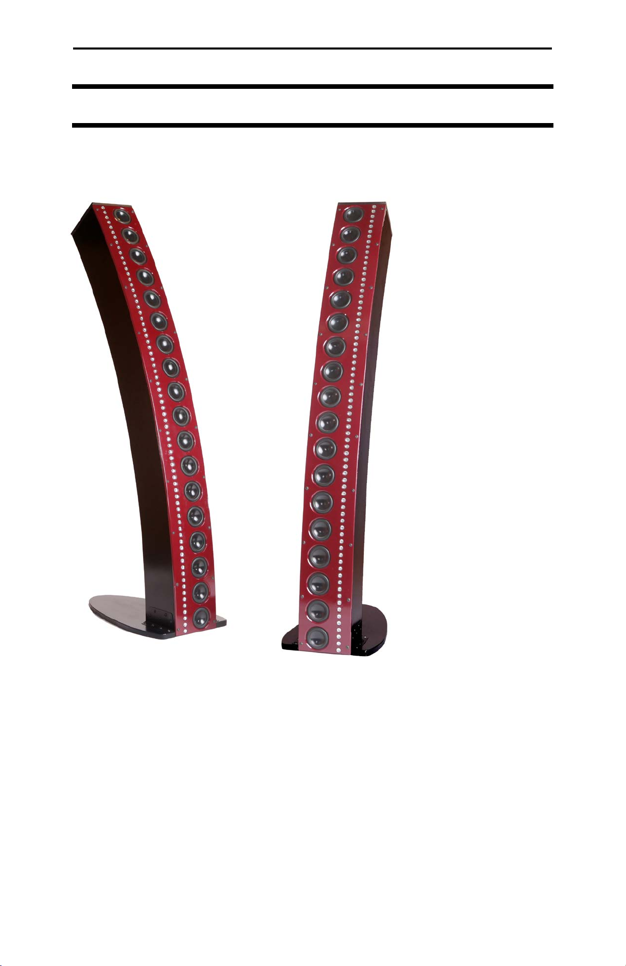
Here is a quick peek at what we supply: 1. Complete cabinet (unfinished), 2. Front panel (unfinished), 3.
All loudspeakers including 36 mid-bass drivers and 144 tweeters (organized into 36 four-tweeter PC
board modules), 4. All resistors, 5. All required screws, fasteners and brackets, 6. All gaskets and sealing
caulk, 7. Two Speakon connectors, 8. Seven spools of multicolored stranded wire, 9. Wire nuts, 10. Rosin
core solder, and 10. A bag of Acousta-Stuf Polyfill absorption material, etc.
These parts are listed and described in the “Material Inventory List” section later in this manual.
1.1.2. What Parts Aren’t Supplied?
Here is a brief list of what we don’t supply: 1. The DSP loudspeaker crossover/EQ, 2. Small tools and
supplies including: wire stripper/cutter, pliers, screw drivers, hex wrenches, batteries, razor blades, and
rulers, etc., 3. Large tools including: soldering station, hot-glue gun, and motorized screwdriver, etc., 4.
Consumables: paint, primer, polishing compounds, electrical tape, sand paper, glue, and RTV Silicone
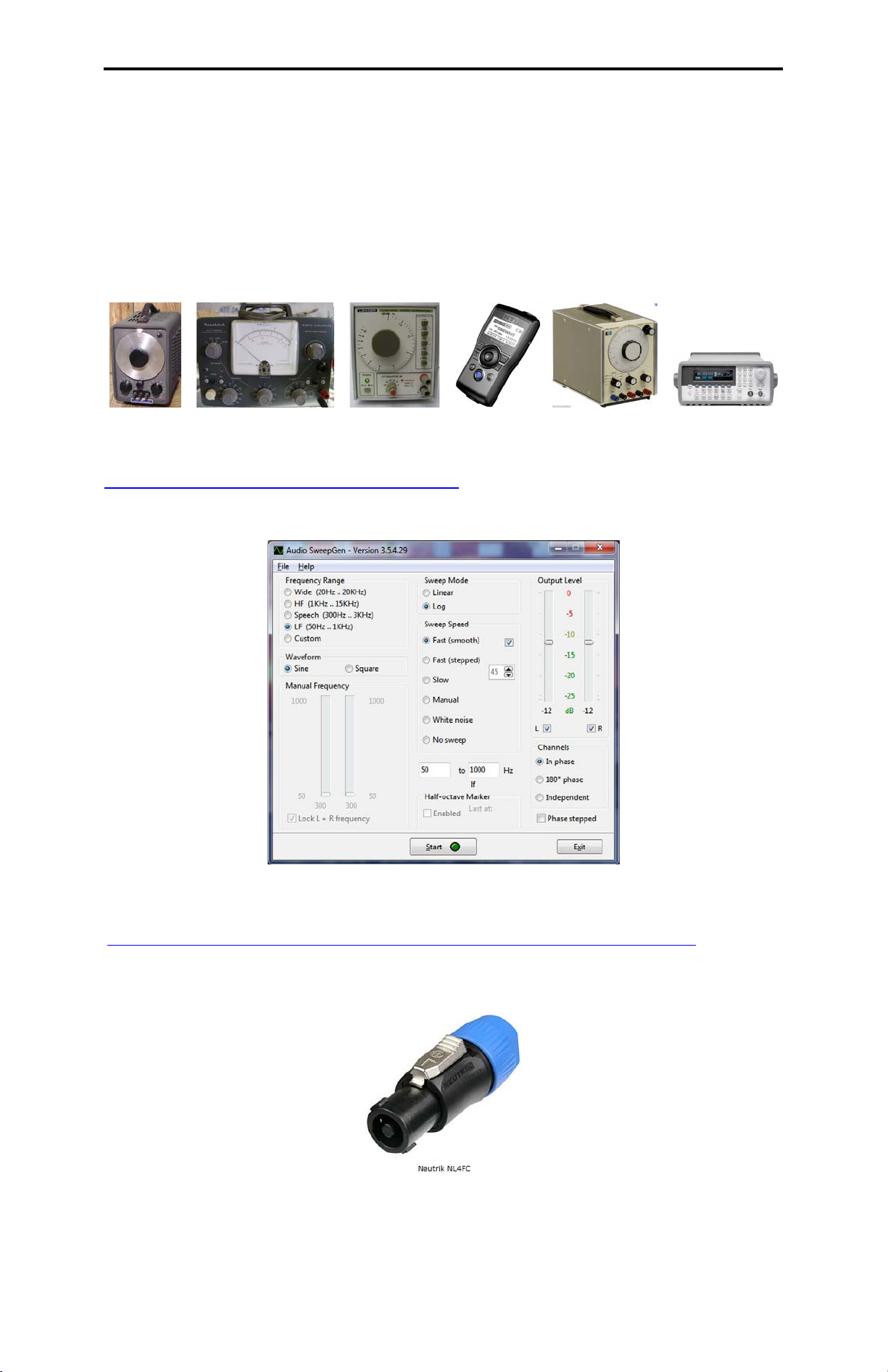
adhesive, etc., and 5. Audio test tools including: microphone, power amplifier, digital multi-meter (DMM)
or AC voltmeter, audio signal generators, and cabling and connectors.
A more detailed list of all the required tools and consumables is listed later in the section “TOOLS AND
CONSUMABLES NEEDED.”
1.1.3. What’s Ahead in the Assembly of the CBT36K?
The construction of the CBT kit consists of 15 main steps:
1) Inventory of all the supplied parts.
2) Preparing the work space.
3) Gathering all required tools and consumables
4) Gathering all gear required for speaker testing including: DMM/AC voltmeter, test microphone,
audio generator, amplifiers, and cables.
5) Sanding and finishing the cabinet.
6) Test all drivers.
7) Prepare the resistors.
8) Prepare the connecting wires.
9) Mount mid-bass drivers and tweeter PC board modules to front panel.
10) Wire mid-bass drivers and tweeter PC board modules.
11) Test polarity and shading network attenuations.
12) Connect drivers to rear panel connector.
13) Install gasket material and acoustic stuffing in the cabinet.
14) Mount front panel with drivers to the cabinet.
15) Wrap up including buzz and rattle tests.
1.1.4. How Long will it Take to Assemble the Kit?
Steps 5, 8, and 14 will take the most time. By far, the most time consuming and demanding step is
number 5 “Finishing the cabinet.” The cabinet finish can range from something as simple as spray
painting it flat black to applying a fine automotive high-gloss metallic finish (like the red automotive
metallic finish of the featured demo units). Sanding and drying time between coats must also be included.
Here are the estimated times for steps 5 to 15 rounded up to the nearest half hour. Depending on your
skill level, your times may vary significantly from these estimated completion times.
Estimated Assembly Time Table (Total Time: 17 Hours, not counting finishing!)
5) 24.0+ Hr, Sanding and finishing the cabinet.
6) 1.0 Hr, Test all drivers.
7) 1.0 Hr, Prepare the resistors.
8) 3.0 Hr, Prepare the connecting wires.
9) 1.0 Hr, Mount mid-bass drivers and tweeter PC board
modules to front panel.
10) 1.0 Hr, Wire mid-bass drivers and tweeter PC board
modules.
11) 2.0 Hr, Test polarity and shading network
attenuations.
12) 1.0 Hr, Connect drivers to rear panel connector.
13) 2.0 Hr, Install gasket material and acoustic stuffing in
the cabinet.
14) 3.0 Hr, Mount front panel with drivers to the cabinet.
15) 2.0 Hr, Wrap up including buzz and rattle tests.
1.2. MASTER CHECKLIST:
To make sure you assemble the right and left stereo pairs of CBT36 cabinets in the correct sequence, the
following master check list must be followed. Each of the steps in this checklist may require several
intermediate steps. This list will also be provided separately as a handout.
Please watch the on-line assembly video before you do any of the following tasks. Itwill give you a
good overview of the assembly of the CBT36.
Page 6of 89

CBT36K Assembly Manual
LEFT RIGHT
1. Un-box all components (two boxes for the cabinet kits and one box for parts).
2. Inventory items received against the CBT36K Material List.
3. Test ND91 Mid-bass drivers and Tweeter modules (Contact Parts Express to report
failures
and request possible replacements).
4. Apply desired finish to all cabinet parts.
5. Prepare resistors
6. Cut and prepare all wire lengths.
7. Load tweeter modules in front panels.
8. Load mid-bass ND91 drivers in front panels.
9. Dry wire (do not solder) all connections for both panels. Soldering is not done at this
point in the assembly process because it is much easier to correct wiring errors if the connections
are not soldered. Soldering will only take place after the wiring is verified correct.
10. Carefully compare your wiring with the front-panel foldout, correct any errors, and
then solder.
11. Glue resistors and dress wiring, apply a drop of finger nail polish to each screw.
12. Test driver polarities.
13. Test shading bank attenuations.
14. Final assembly.
15. Setup external active Crossover.
16. Setup the remaining part of the system including line level connections and speaker
cable connections to power amps.
17. Power up for the first time and make sure it works.
18. DONE! Whew! Enjoy!
1.3.WORK AREA:
Find a comfortable well-litplace to assemble your kit. You will need a 6 ft or longer table adjusted to the
proper height depending on if you prefer to work standing up or sitting down. It is a good idea to cover the
surface in a soft carpet to prevent scratching the painted parts. You will need access to A/C power for
soldering irons and glue guns. Refer to Figs 1 and 2 at the start of this manual for illustrations of the work
area for the CBT36 prototypes.
1.4.SAFETY FIRST:
During the process of assembly you will be using tools and chemicals that could be harmful to your
health. Wear appropriate eye protection, respirators and protective gloves during the sanding and
painting steps and always work in an area that has plenty of ventilation and lighting. Eye protection is very
important when trimming leads and wires and make sure the area is well ventilated during soldering.
Soldering irons can reach very high temperatures (800 degrees) and soldering iron burns are very painful
and most importantly soldering irons can cause fire if left unattended so NEVER LEAVE A SOLDERING
IRON UNATTENDED. Always think safety first.
Page 7 of 89

CBT36K Assembly Manual
Page 8of 89
2. WHAT’S NEEDED?
2.1. TOOLS AND CONSUMABLES NEEDED:
In addition to the items supplied with the kit you will need some basic tools and consumables to complete
your CBT36 kit. Refer to the lists below and the following photos for a quick overview of the required tools
and consumables (NOTE:Painting supplies are shown in the cabinet finishing section of this manual).
Fig. 3. Tools and consumables required in the assembly of the CBT36. See the following two
lists for individual items.
2.1.1. Tools:
1) Wire stripper
2) Wire cutters
3) Needle nose pliers
4) 4mm or 5/32 Allen (Hex) tool
5) #2 Phillips screw driver
6) Ratchet with adapter for a Phillips screw driver
7) Sharpie felt tip pen
8) Yard or meter measuring stick
9) Soldering Iron
10) Hot glue gun and glue sticks
11) Test leads
12) 1.5v and two - 9v batteries
13) Single-edge razor blades or Exacto knife and blades
2.1.2. Consumables:
1) Sand paper grits 150, 180, 220, 320, 400
2) Primer
3) Paint
4) Polishing compounds (for automotive finishes)
5) Thin (not a GEL) Super Glue
6) RTV silicone adhesive (not shown)
7) Can of compressed air or air hose with nozzle connected to a compressor
8) Finger nail polish (your favorite color)
9) Electrical tape (not shown)

CBT36K Assembly Manual
2.2. AUDIO MEASUREMENT TOOLS:
The following software tools, equipment, and supplies will help in the measurement and testing of the
CBT36 arrays.
2.2.1. Stand-Alone Generators:
It would help if you have on hand an audio generator or function generator such as the following (listed
without descriptions and lifted from Google Images. You old timers may remember some of these
generators!):
2.2.2. Signal Generator Free-Software Options:
2.2.2.1. David Taylor Audio SweepGen Signal Generator:
http://www.dxzone.com/cgi-bin/dir/jump2.cgi?ID=17725
This generator is free on the Internet and is easy to use. It will generate continuous sine/square signals
plus log/linear stepped/continuous sweeps from arbitrary start-stop frequencies.
2.2.3. Speaker Connector Cable and Wiring Options:
2.2.3.1. Do-it-Yourself Speaker Cable:
http://www.parts-express.com/neutrik-nl4fc-speakon-connector-4-pole-cable-mount--092-050
If you wish to construct your own test cable or your own a pair of speaker cables, order two of the Neutrik
Speakon NL4FC four-wire speaker connectors for the CBT36 connection and the appropriate four-
conductor 16 AWG or larger cable and connectors to mate with your power amplifier.
2.2.3.2. Speakon Connector Wiring and Documentation:
http://www.n4tze.com/speakonconnectorwiring.pdf
This document will help explain the Speakon NLF4C connector and its wiring.
Page 9 of 89

CBT36K Assembly Manual
Page 10 of 89
2.2.4. Test Power Amplifierswith Volume Control:
The following two Dayton Audio power amplifiers, available from Parts Express, are good quality, relative
inexpensive,and have a power rating of ten watts or greater:
2.2.4.1. Dayton Audio DTA-120 Class T Mini Amplifier 60 WPC:
http://www.parts-express.com/dayton-audio-dta-120-class-t-mini-amplifier-60-wpc--300-3800
2.2.4.2. Dayton Audio APA150 150W Power Amplifier:
http://www.parts-express.com/dayton-audio-apa150-150w-power-amplifier--300-812
2.2.5. Digital Multi-meter:
2.2.5.1. Triplett 1101-B Compact DMM with Backlit Display:
http://www.parts-express.com/triplett-1101-b-compact-dmm-with-backlit-display--391-062
2.2.6. Analyzer Options:
These are optional advanced measurement tools.
2.2.6.1. ARTA Audio Measurement and Analysis Software:
http://www.fesb.hr/~mateljan/arta/

CBT36K Assembly Manual
Page 11 of 89
2.2.6.2. Dayton Audio OmniMic V2 Precision Measurement System:
http://www.parts-express.com/dayton-audio-omnimic-v2-computer-based-precision-room-measurement-system--390-792
This is the Dayton Audio OmniMic V2 System, a USB microphone and analysis software combination.
2.2.6.3. Dayton Audio DATS V2 Computer Based Audio Component Test System:
http://www.parts-express.com/dayton-audio-dats-v2-computer-based-audio-component-test-system--390-806
2.2.7. Measurement Microphone Options:
These are optional advanced measurement tools.
2.2.7.1. Behringer ECM8000 Measurement Microphone:
http://www.parts-express.com/behringer-ecm8000-measurement-microphone--248-625
2.2.7.2. Dayton Audio EMM-6 Electret Measurement Microphone:
http://www.parts-express.com/dayton-audio-emm-6-electret-measurement-microphone--390-801
2.2.7.3.Dayton Audio OmniMic V2 Precision Measurement System:
http://www.parts-express.com/dayton-audio-omnimic-v2-computer-based-precision-room-measurement-system--390-792
This is the Dayton Audio OmniMic V2 System, a USB microphone and analysis software combination.

Page 12 of 89
3.1.2. Material List in Detail:
ITEM QTY DESCRIPTION: IMAGE:
1 2 3.1.2.1. MDF Cabinet Kit:
Make sure you identify left and right cabinets. To do this,
locate the holes at the bottom of each cabinet and position
those next to each other and verify that the tweeter holes are
next to one another.
2 2 3.1.2.2. Cabinet Base:
34 3.1.2.4. Base Mounting Bolts:
440 3.1.2.6. Front-Panel Mounting Screws:
1-1/2 inch x 1/4-20 round Allen head screws. These screws
attach the front panel to the enclosure (20 per enclosure).
NOTE:These screws are not supplied separately. The come
with the un-finished cabinet assembly and attach the front
panel to the cabinet. The front panel will be removed when the
assembly process is started and they must be saved for later
reuse.
5292 3.1.2.7. Mid-Bass Driver and Tweeter Module Mounting Screws:
Two bags each containing 146 each 6-32 x 5/16 screws.
These screws attach the mid-bass drivers and tweeter
modules to the inside of the front panel.
CBT36K Assembly Manual
3. WHAT’S HERE?
3.1. MATERIAL INVENTORY LIST:
64 3.1.2.9. Neutrik Speakon NL4MP Connector Screws:
One bag containing four #4 x 5/8" flat head Phillips wood
screws.

CBT36K Assembly Manual
Page 13 of 89
82 3.1.2.12.Sound Absorption/Dampening Fiber:
Two One lb bags of Acousta-Stuf Polyfill absorption material.
93 3.1.2.13.Speaker Sealing Caulk:
One 36 inch roll of ¼ inch wide sealing caulk. This caulk is
used for wire management on the back of the front panels.
Strips are self-adhesive and stick easily to any surface it is
pressed against.
10 2 3.1.2.14.Four-wire Chassis-Mount Speaker Connector:
Neutrik Speakon NL4MP. Each cabinet has one of these
mounted on the bottom rear of the cabinet. The connector has
four wires which allow the both the mid-woofers and the
tweeters of the CBT36 to be connected with one connector.
A good reference for Speakon connectors and wiring is found
at: http://www.n4tze.com/speakonconnectorwiring.pdf.
11 2 3.1.2.15.Resistor, Non-Inductive Wire-Wound, 1.0 Ohm:
Mills brand, 12W, 1% Tolerance.
12 10 3.1.2.16.Resistor, Non-Inductive Wire-Wound, 1.5 Ohm:
Mills brand,12W, 1% Tolerance. (NOTE: Image shows a 1.0 Ohm.)
13 4 3.1.2.17.Resistor, Non-Inductive Wire-Wound, 2.0 Ohm:
Mills brand,12W, 1% Tolerance. (NOTE:Image shows a 1.0 Ohm.)
14 2 3.1.2.18.Resistor, Non-Inductive Wire-Wound, 2.5 Ohm:
Mills brand,12W, 1% Tolerance. (NOTE: Image shows a 1.0 Ohm.)
15 4 3.1.2.19.Resistor, Non-Inductive Wire-Wound, 3.0 Ohm:
Mills brand,12W, 1% Tolerance. (NOTE: Image shows a 1.0 Ohm.)
16 4 3.1.2.20.Resistor, Non-Inductive Wire-Wound, 5.0 Ohm:
Mills brand,12W, 1% Tolerance. (NOTE: Image shows a 1.0 Ohm.)
71 3.1.2.10.Front Panel Gasket Material:
One 36 ft roll of 1/2 inch wide x 1/16 inch thick Neoprene
Sponge. 18 ft of this gasket material will be used per speaker.

CBT36K Assembly Manual
Page 14 of 89
18 36 3.1.2.22.Mid-Bass Driver:
Dayton Audio ND91-8, 3-1/2" Aluminum Cone Full-Range
Driver 8 Ohm: http://www.parts-
express.com/pe/showdetl.cfm?Partnumber=290-226
19 36 3.1.2.23.Mid-Bass Driver Gasket:
Dayton Audio part which may be packed in the mid-bass
driver box.
20 1 3.1.2.24.Hook-UpWire, 18 AWG, RED:
Stranded, 25 ft. spool, tinned copper conductor,
Consolidated brand. For ND91 Mid-Bass wiring.
21 1 3.1.2.25.Hook-UpWire,18 AWG, BLACK:
Stranded, 25 ft. spool, tinned copper conductor,
Consolidated brand. For ND91 Mid-Bass wiring.
17 36 3.1.2.21.Tweeter Module Assembly:
Four tweeters mounted on PC board, Dayton Audio model
ND13TG-8.
The 3/4" diameter wide-range tweeters are made by Dayton
Audio, and feature a 0.5” edge-drive inverted aluminum dome
that utilizes a high-energy neodymium magnet for low
distortion and high efficiency. The tweeters are mounted on
PC boards in groups of four to ease assembly and optimize
center to center spacing. The center-to-center spacing of the
tweeters is 22.7 mm (0.892”).
22 1 3.1.2.26.Hook-UpWire,18 AWG, GREY:
Stranded, 25 ft. spool, tinned copper conductor,
Consolidated brand. For ND91 Mid-Bass wiring.
23 1 3.1.2.27.Hook-UpWire, 18 AWG, YELLOW:
Stranded, 25 ft. spool, tinned copper conductor,
Consolidated brand. For ND91 Mid-Bass wiring.

CBT36K Assembly Manual
Page 15 of 89
24 1 3.1.2.28.Hook-UpWire, 24 AWG, BLACK:
Stranded, 25 ft. spool, tinned copper conductor,
Consolidated brand. For tweeter wiring.
25 1 3.1.2.29.Hook-UpWire, 24 AWG, RED:
Stranded, 25 ft. spool, tinned copper conductor,
Consolidated brand. For tweeter wiring.
26 1 3.1.2.30.Hook-UpWire, 24 AWG, YELLOW:
Stranded, 25 ft. spool, tinned copper conductor,
Consolidated brand. For tweeter wiring.
27 1 3.1.2.31.Solder, 60/40 Rosin Core:
Diameter 0.031", 0.50 oz. tube, 15 ft., Kester brand Pocket
Pack.
28 10 3.1.2.32.Wire Nuts:
NTE twist on wire connector (22-14) AWG grey with spring
insert.

CBT36K Assembly Manual
Page 16 of 89
4. CABINET FINISHING:
4.1. FINISHING THE CABINET:
The CBT36 front panel is finished separately from the rest of the cabinet components. As noted below,
the front panel is finished with an acrylic automotive finish while the rest of the cabinet is finished in a low-
luster black lacquer. The following steps describe the finishing of both sections of the cabinet.
4.1.1. Gather All Items to be Painted:
Gather all the items that need to be painted. Remove the front panel from the cabinet by removing all (20)
of the ¼-20 x 1.5 inch machine screws using the Allen tool specified above and set it aside for the
moment. If you are new to finishing, it is best to finish your kit in groups. For instance, start with the top
caps and bases because these are smaller parts that will give you practice before you start work on the
main cabinet.
4.2. SELECT PAINTING SYSTEM:
You must select a painting system and color for your cabinets. Consult your painting supply vendor for
options. All cabinet components except for the front panel of the original CBT36 are painted with a low-
luster black pre-catalyzed lacquer. The front is painted with a metal-flake acrylic automotive finish.
Fig. 4. CBT36 cabinet showing front panel being unscrewed.

CBT36K Assembly Manual
4.3. CABINET FINISHING:
4.3.1. Cabinet Sanding:
MDF parts are sanded after they come off the CNC machine and assembly area, so most of the work is
already done for you. However to achieve a high end finish you will need to sand and prime the parts. We
recommend that you start with 150 grit sand paper to sand the edges, this will remove remaining tool
marks. Next move to 180 grit and continue sanding the edges and finally use the 220 grit sand paper.
4.3.2. Prime the Cabinet Surface:
Apply a heavy solids primer compatible with the paint system you have chosen, if you spray the primer
on, you will need to consult the paint vendor for recommendations on tip diameter and air pressures.
Allow the primer to cure for the specified time prior to sanding. Start with 220 grit and sand all surfaces
lightly, but pay particular attention to the edges. Step up to 320 grit paper and again sand all surfaces
lightly and finally move to 400 grit and again sand all surfaces. If you wish, you can continue to 600 grit
sand paper as the last sanding step.
4.3.3. Cabinet Painting:
Apply a minimum of three coats of paint to the cabinet. A light texture looks good on the CBT36 cabinet
and is easily achieved by lowering the air pressure on the spray gun so the droplets of paint become
larger. After the last coat dries, you can give the cabinet a textured look by lightly misting the cabinet with
paint under low air pressure. You should practice this on some scrap material to make sure you get the
hang of it prior to spraying your cabinets.
4.4. FRONT PANEL FINISHING:
The front-panel color of the systems shown at the start of this manual and in the Parts-Express catalog is
General Motors Paint Code: 3986 called medium garnet red. See Ditzler PPG:
http://paintref.com/cgi-bin/paintdetail.cgi?ppg=3986,
http://paintref.com/cgi-bin/colorcodedisplay.cgi?ditzler=3986,
and http://www.ppg.com/coatings/autooem/about/Pages/History.aspx.
The following figure shows an example of these front-panel finishing consumables.
(See http://www.ppg.com/coatings/refinish/en/products/omni/Pages/default.aspx, also
http://www.growautomotive.com/high-efficiency-solvents.php).
Fig. 6. Consumables for finishing the front panel of the CBT36 cabinet.
Finishing the front panels follows the same steps as above for the cabinet but you need to be very careful
working around the tweeter holes. The MDF is machined to 30 thousandths thickness and can be
damaged by aggressive sanding. The bevels where the mid-bass drivers mount require the most
attention. Sand through all the steps as described above and you may want to brush on a coat of primer
on these surfaces and repeat the pre-primer sanding process prior to spraying the entire front panel with
primer.
The painting system applied to the CBT36 front panel starts with a heavy-solids primer, followed by two
coats of the metallic base, followed by two coats of high gloss top coat. Allow the paint to cure the
specified time between each coat. If you take your time and do a good job sanding the primer, you should
not need to sand between the base coats. The top coat can be polished with automotive polishing
compounds and a buffing wheel to give a metallic looking finish.
4.4.1. After Painting isComplete Start the Assembly:
Once painting is complete, the rest of the assembly process will move quickly. Just follow the Master
Check List at the beginning of this manual and it will guide you through each section.
OK, it’s time to start building this amazing new speaker!
Page 17 of 89

CBT36K Assembly Manual
Page 18 of 89
5. TESTING AND PREPARATION OF
WIRES, COMPONENTS, AND
RESISTORS:
5.1. TEST ALL MID-BASS DRIVERS
AND TWEETER MODULES:
These steps must be done first to insure that all the
drivers are operating satisfactorily.
5.1.1. Check the ND91 Drivers for Debris
in the Voice Coil:
Hold the driver close to your ear and press the
center of the cone gently and listen for scraping
noises. Good drivers are completely quiet!
5.1.2. Check ND91 Voice Coil Polarity:
5.1.2.1. Connect test leads:
Connect test leads to the ND91. RED clip to the (+)
terminal and BLACK clip to the (-) terminal.
5.1.2.2. Connect the other ends of the test leads to a
battery:
Hold the BLACK test lead to the (-) side of a 1.5v
battery and tap the RED test lead on the (+) side of
the battery. The cone should move out!
5.1.3. Check Tweeter Module Voice Coil
Polarity:
Here you will check the polarity of each of the
tweeter modules (36 in all).
5.1.3.1. Look for the Red Mark on the Positive
Tweeter Terminal:
Locate the Red marks on the tweeter module.

CBT36K Assembly Manual
Page 19 of 89
5.1.3.2. Connect the test leads to the tweeter
module:
Connect the test leads to the tweeter module as
shown above. The RED test lead connects to the
side with the RED mark on the driver (see next
photo).
5.1.3.3. Connect the other ends of the test leads to a
battery:
Hold the BLACK test lead to the (-) side of a 1.5v
battery and tap the RED test lead on the (+) side of
the battery. All cones should jump forward. If none
move, double check your connections and the
module itself.
5.1.4. Check DC Resistance of ND91 Mid-
Bass Voice Coil:
Set the DMM to ohms and check the DC
resistance of the voice coils for all 36 ND91s. The
reading will be very close to eight Ohms. (For more
accuracy in the measurement first short the test
leads together before connecting the drivers and
subtract that reading from the measurements for
each driver). You may also use the Parts Express
WT3 to measure the impedance. This reading is
very sensitive to noise and vibration. Make this
measurement in a quiet area.
5.1.5. Check DC Resistance of Tweeter
Modules:
Following the same procedure as in the previous
section, check the DC resistance of the tweeter
modules. Connect your test leads to the same
locations as the tweeter polarity test. The reading
also should be quite close to eight Ohms.
5.2. PREPARE THE RESISTORS:
Overview:
Two sets of parallel resistors with different lead
configurations are prepared in the following steps.
The first parallel combination has straight leads
coming from the resistor body:
The second parallel combination has a 90° bend in
the left lead:
These parallel resistor combinations will be
prepared in the following steps.
5.2.1. Position Resistors:
Position the resistors as shown (check the resistor
configuration list, shown later in Section 5.2.5, to
determine which resistors get connected this way).

CBT36K Assembly Manual
Page 20 of 89
5.2.2. Bend Resistor Leads:
Bend the leads on one of the resistors as shown.
5.2.3. Wrap the Bent Leads:
Wrap the bent leads three times around the
straight leads.
5.2.4. Trim Longer Leads:
Trim the longer leads to 1/2 inch and trim the
twisted wire close to the long lead.
Save the longer cutoffs for later use. (20 will be
needed later!)
5.2.5. Straight-Lead Parallel Resistor
Configurations:
Prepare eights sets of straight-lead parallel resistor
combinations following the previous photos (each
set has two resistors in parallel), as follows:
1) 5 Ohm and 5 Ohm (two pairs)
2) 3 Ohm and 3 Ohm (two pairs)
3) 2 Ohm and 2 Ohm (two pairs)
4) 1.5 Ohm and 1.5 Ohm (two pairs)
5.2.6. Bent-Lead Parallel Resistor
Configurations This One is Different!
Configure two sets of parallel 1.5 Ohm resistors
with a 90 deg bend on the left side as shown in the
following photo. The part that bends downward
should be about 1/4 of an inch long.
1) 1.5 Ohm and 1.5 Ohm (two pairs)
5.3. CONFIGURE AND TRIM THE
RESISTOR LEADS:
Configure and trim the leads as shown for two
each of 1.0, 1.5 and 2.5 ohm resistors.
5.3.1. Bend Leads:
Bend the right lead 90 degrees after it exits from
the resistor body.
5.3.2. Second Bend:
Hold the lead with needle nose pliers and make a
second bend as shown.
This manual suits for next models
1
Table of contents