DC Matic TL-900 User manual

Model TL-900
Safety and Use Manual
24-30 VDC Powered
3/4 Inch Drive Impact Wrench System
Work Area Safety
Keep work area clean and well lighted. Cluttered or dark areas invite accidents. Use the LED
light work light on the Model TL-900 (shown in Fig. 1) whenever possible to reduce injuries.
Do not operate the Model TL-900 in explosive atmospheres, such as in the presence of
flammable liquids, gases or dust. Although the Model 900 incorporates safety measures that
enclose sparks, its exterior metal parts may create sparks that can ignite flammable materials.
Keep bystanders, children and visitors away while operating the Model TL-900. Distractions
can cause you to lose control.
Make sure vehicles are braked, chocked and stable.
Use extreme caution when working on or around a vehicle on a jack.
Electrical Safety
The Anderson quick connector ( shown in Fig. 1) on your Model TL-900 must match another
Anderson quick connector. Mismatched connectors create the risk of electrical shorting.
Make sure the cables, switches and power connector are in good working order
before making a secure connection. Damaged cables, plug, switches or receptacles will reduce
the amount of power available to the tool and potentially cause damage to it or the vehicle.
Do not immerse the Model TL-900 in standing water.
Do not abuse the power cables. Never use the cord for carrying, pulling or unplugging the
tool. Keep the cables away from sharp edges and moving parts.
Make sure the power cables are free from snags and tangles before operating the tool sys-
tem.
Personal Safety
Always stay alert and use common sense when operating the Model TL-900. Never operate
the tool while tired or under the influence of drugs, alcohol or medication. The Model TL-900
is a very powerful tool that can cause serious personal injury and property damage if not properly
used.
Use safety equipment. Always wear eye and ear protection. Safety equipment such as dust
masks, non-skid safety shoes, hard hat or hearing protection used for appropriate conditions will
reduce personal injuries.
Avoid accidental start up of the Model TL-900 by applying power only when ready to use. Un-
plug immediately when work is completed. Keep the trigger free from obstructions.
Make sure any attachments such as sockets, adapters and torque extensions are secured to
the tool’s square drive prior to operating the Model TL-900.
Do not overreach. Keep proper footing and balance at all times. Make sure cables are free
from snags and tangles when using the Model TL-900 off the ground.
Dress properly. Do not wear loose fitting clothing or jewelry. Make sure hair, clothing and
gloves are away from moving parts.
Keep your Model TL-900 handle clean from oil and grease. Holding a slippery handle will
make it difficult to safely control this powerful tool.

Tool Use And Care
Operate the Model TL-900 in 1 - 2 second long bursts. If the tool does not loosen the fastener
(nut or bolt) after (3) 1 –2 second bursts STOP and use other means to loosen the fastener.
Use only impact “rated” sockets. Non-impact sockets can break and cause
personal injury or property damage.
Always finger tighten fasteners before securing with the Model TL-900 to avoid cross-
threading.
Make certain that impact sockets are securely seated over the fastener prior to tightening or
loosening a bolt or nut.
Always use the correct size impact socket size. Incorrect sockets can damage the fastener or
slip off causing injury.
Always clean your Model TL-900 and all electrical connectors after use.
Operating Instructions
Hold the Model TL-900 firmly using both hands while operating it. Always wear safety gog-
gles or other approved eye protection. Heavy impacting can cause flying debris that can cause
permanent eye damage.
Sockets and fasteners can get hot during operation. Use protective gloves when handling them.
Do not operate the Model TL-900 for long periods of time. Vibration caused by the tool’s impact-
ing action may be harmful to your hands and arms. Use thick gloves to provide extra cushion and
limit exposure by taking frequent rest periods.
Operating Voltage
Your Model TL-900 requires a source of 24-30 VDC that is capable of providing 100 AMPS
(intermittent) to generate optimum impacting strength.
If you have a solid source of 24-30 VDC applied to your Model TL-900 and the impacting strength of the
tool seems sluggish or weak, please contact DC-Matic to obtain a return authorization (RMA) so we can
expedite the repair or replacement of your tool or arrange to have a new set of motor brushes sent to
you.
Thermal Protection/Cut Off
Your Model TL-900 is equipped with an internal, bi-metal thermostat that will shut-down the tool (kill the
trigger switch) when the tool becomes over-heated. Testing has revealed that this tool’s thermal
protection circuit will not activate if the Model TL-900 is used intermittently and allowed an adequate
amount of cool-down time between uses.
Note: When used in an ambient temperature of 90 degrees F the average amount of time needed for
the thermal protection circuit to re-set time is (30) minutes.
Control Box
Your Model TL-900 is equipped with a forward-positioned, 12-cluster LED work light (shown in Fig. 1).
The work light’s On/Off switch is located on the control box (shown in Fig. 3). To achieve the highest
degree of workplace safety always turn ON the work light when operating the Model TL-900 in a low or
no-light environment. The control box is “Factory Sealed” and must remain that way. Unauthorized
opening of the control box will void the tool’s warranty.
2

Input Power Connector
The Control Box that is part of your Model TL-900 is equipped with an Anderson Connector that is rated
for 175 amps of current. Before connecting your Model TL-900 make certain that this connector is free
of
debris and in good condition.
Impacting Mechanism
Your Model TL-900 is equipped with the highest quality, twin-hammer impacting mechanism (shown in
Fig. 1) It is factory lubricated and sealed so it is not necessary to service it in the field.
Do-It–Yourself Motor Brush Set Replacement
Your Model TL-900 is equipped with (4) external brush ports that will allow you to quickly and
easily replace your initial set without having to remove the 24 VDC motor from the tool’s plastic housing.
Each brush can be removed and replaced by using a standard flat-blade screw driver in minutes (shown
in Fig. 2).
Repairs
To achieve the highest degree of user safety and tool reliability, all repairs (excluding brush set
replacement) to your Model TL-900 must be performed by an authorized repair location. Please contact
DC-Matic Enterprises, Inc. for immediate support of your Model TL-900 and for proper product return
(RMA) instructions or to purchase a replacement brush set.
Returns
Each returned product must first be issued a RMA (returned merchandise authorization) by DC-Matic
Enterprises, Inc. Do not ship your tool back without a company issued return authorization
(RMA). To request an RMA call toll-free 1-(866)-419-5602
Note: Returned units must be shipped transportation prepaid to DC-Matic’s designated repair facility
noted on the RMA.
Warranty
DC-Matic Enterprises will repair or replace, without charge, any portion of your Model TL-900 tool
if a defect or failure was proved to be caused by faulty material or workmanship for a period of
ONE FULL YEAR from the date of purchase. Proof of purchase date is required for all
warranty claims. Warranty DOES NOT provide repair or replacement if it is determined that any
portion of the tool system failed due to abuse or when repairs were made or attempted by any
one other than “authorized” repair facility personnel. Please take the time to register your Model
900 using the mail-in Warranty Registration Card included in this packet or register the tool
online at www.dcmatic.com
Note: Each Model TL-900 has a manufacturer’s ID plate with serial number affixed to the bottom
of the tool’s Control Box ( shown in Fig. 4) for Warranty Verification purposes.
3

1
Environmentally Sealed Work Light
On / Off Rocker Switch
Fig. 1
Fig. 4
Mfr. Serial # Plate
Forward-Reverse
Rocker Switch
Control Box
8 Foot Long
Power Cord
175 Amp Anderson Quick Connector
Forward-Mounted Control
Brush Cap
Trigger Switch
12-Cluster LED
Work Light
3/4 Inch Drive-Twin-Hammer
Impact Assembly With Snap-
Ring Retainer
Solid Brass Brush Retainer Cap /PlugBrush
Port Cap
Replacement Brush
Standard Flat-Blade
Screw Driver
Fig. 3
Fig. 2
Control Box
4
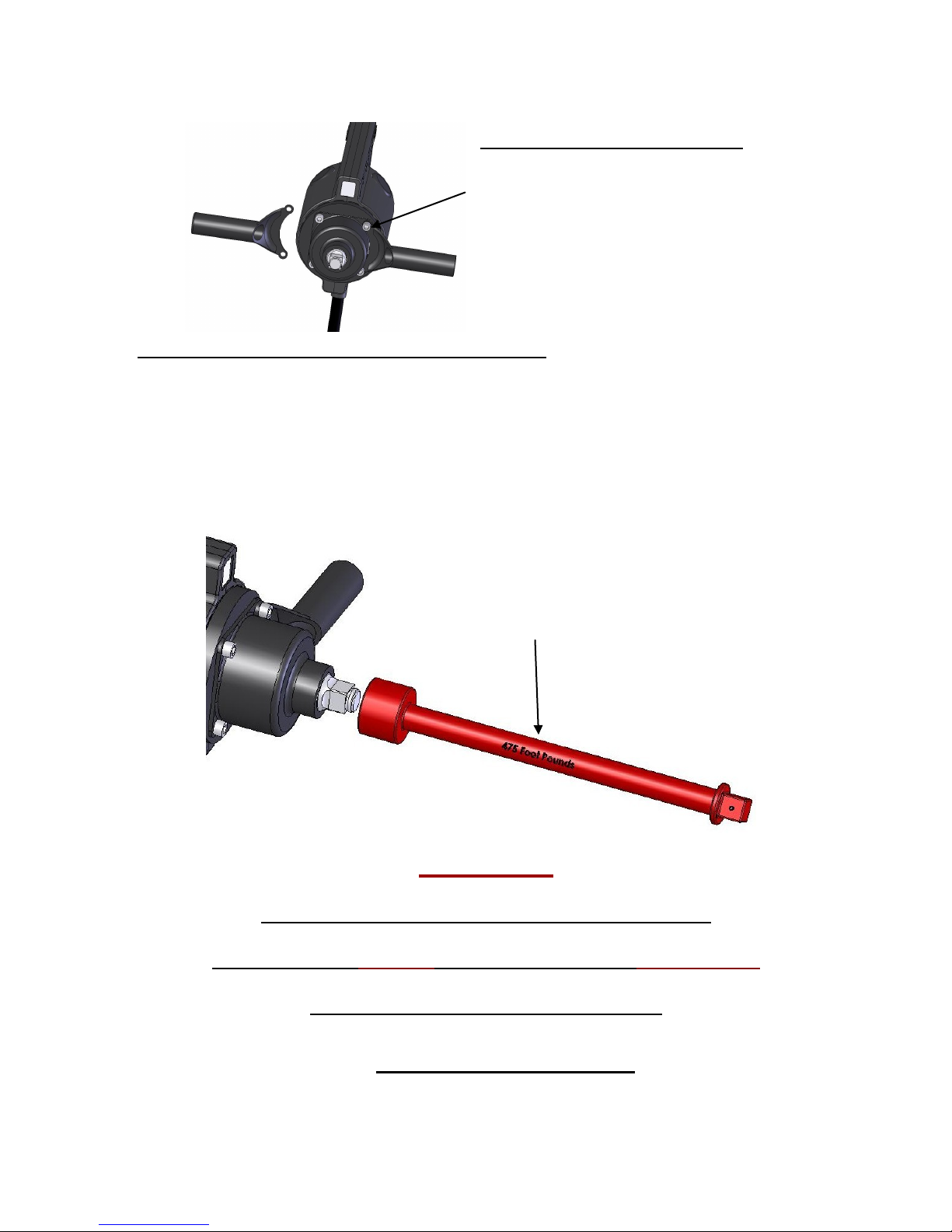
Fig. 5
Properly Controlling Output Impacting Torque
DC-Matic Enterprises, Inc. markets (4) individual 3/4 inch drive “torque limiting
extensions” calibrated at 175, 250, 350 and 475 foot pounds. When attached to the
Model TL-900 a burst of (2) seconds of tool run time will yield an output (impacting
torque) limited within the range (plus or minus 10 %) that is marked on the extension. It
must be noted that a longer than (2) second burst will yield a greater amount of
impacting torque.
WARNING
Excluding the do-it-yourself replacement of motor
brushes, please DO NOT attempt to repair your Model TL-900.
Doing so will void the tool’s WARRANTY.
Fig. 6
475 Foot Pound
Torque Limiting Extension
By removing the (4) allen-head cap screws
that secure the hammer assembly to the
tool, the stabilizing handle can be moved
to the other side as shown.
Stabilizing Handle Placement
5
www.dcmatic.com
Table of contents
Popular Impact Driver manuals by other brands


Sealey
Sealey CP400LI instructions

Haussmann Xpert
Haussmann Xpert PNT104-B Operator's manual

Parkside
Parkside PDSSE 450 A1 Translation of the original instructions

Ryobi
Ryobi R18IDBL Original instructions

Paoli Avvitatori
Paoli Avvitatori RED DEVIL 2.0 street legal Operating and maintenance manual

DeWalt
DeWalt DCF911 manual