DC Pedals 5-Channel Bluetooth Looper User manual

User Manual

5-Channel Bluetooth Looper –User Manual
©2019 DC Pedals. All Rights Reserved. r3.1 Page 2 of 12 www.dcpedals.com
DC Pedals™5-Channel Bluetooth Looper
Our 5-Channel Bluetooth Looper is a microcontroller controlled programmable looper effects true-bypass
switching system with five loops, 100 direct accessible presets, 100 MIDI accessible presets, MIDI input and
MIDI output, and our patented Bluetooth wireless programming and control. Use your iOS or Android
mobile device and our VirtualLooper™ app to control and program your looper in real-time. And use the app
off-line to create and manage presets, then download to the looper seconds after setup. The Looper supports
two operational modes, Live Mode and Preset Mode described in the next section of this document.
Operation (Version 5.x Firmware)
The looper operates on 9-18 volts DC. After it completes power-up, it restores itself to how it was set when it
last powered off. It operates in either of two modes described below (Live or Preset Mode). It also supports
a Programming Mode for creating new presets, a Save Mode to save a preset, and a Configuration Mode.
Configuration Mode is used to configure the global preset, MIDI input channel, MIDI output channel, MIDI PC
messages, MIDI CC responses, MIDI through, audio mute, and TRS controls. Programming is accomplished
using the footswitches and can be completed in seconds using just your feet. Programming and real-tine
control can also be done through the VirtualLooper™ mobile app available for Android and iOS.
Presets are arranged in banks and banks are arranged in folders. There are five presets accessible in each
bank. The Bank switch increments the bank from Bank 1 to Bank 5, then back to Bank 1. Twenty-five
presets are quickly accessible via the Bank and Channel switches. There are also four folders that can be
used to organize your presets. Hold the Bank switch 2 seconds and the Looper enters a Folder Select state.
The Looper will blink the currently selected folder LED and light solid the other LEDs, with LED 5 remaining
OFF. Press a Channel switch (switches 1-4) to select a new folder. The Looper will quickly blink the new
Folder LED. Now you have another 25 presets accessible via the Bank and Channel switches.
Firmware Revision Notes
Firmware version number is written on the pcb or chip inside the bypass looper. Firmware updates are
performed by technicians only. Contact us for details.
Revision 5.09 –12/29/18
•Added feature to convert Tuner switch to Bank Down switch. Hold the Tuner switch in Preset Mode to
toggle this feature.
•Added short and long mute times.
•Changed the mute software to mute only once for each preset change. Previously, the mute would
activate for when toggling each loop.
•Added notification to the VirtualLooper app when loading global preset.
Revision 5.08 –10/13/18
•Fixed an issue during power up with certain power supplies. Looper would not reliably start with
certain power supplies.
Revision 5.07 –Initial release
5-Channel Bluetooth Looper –User Manual
©2019 DC Pedals. All Rights Reserved. r3.1 Page 3 of 12 www.dcpedals.com
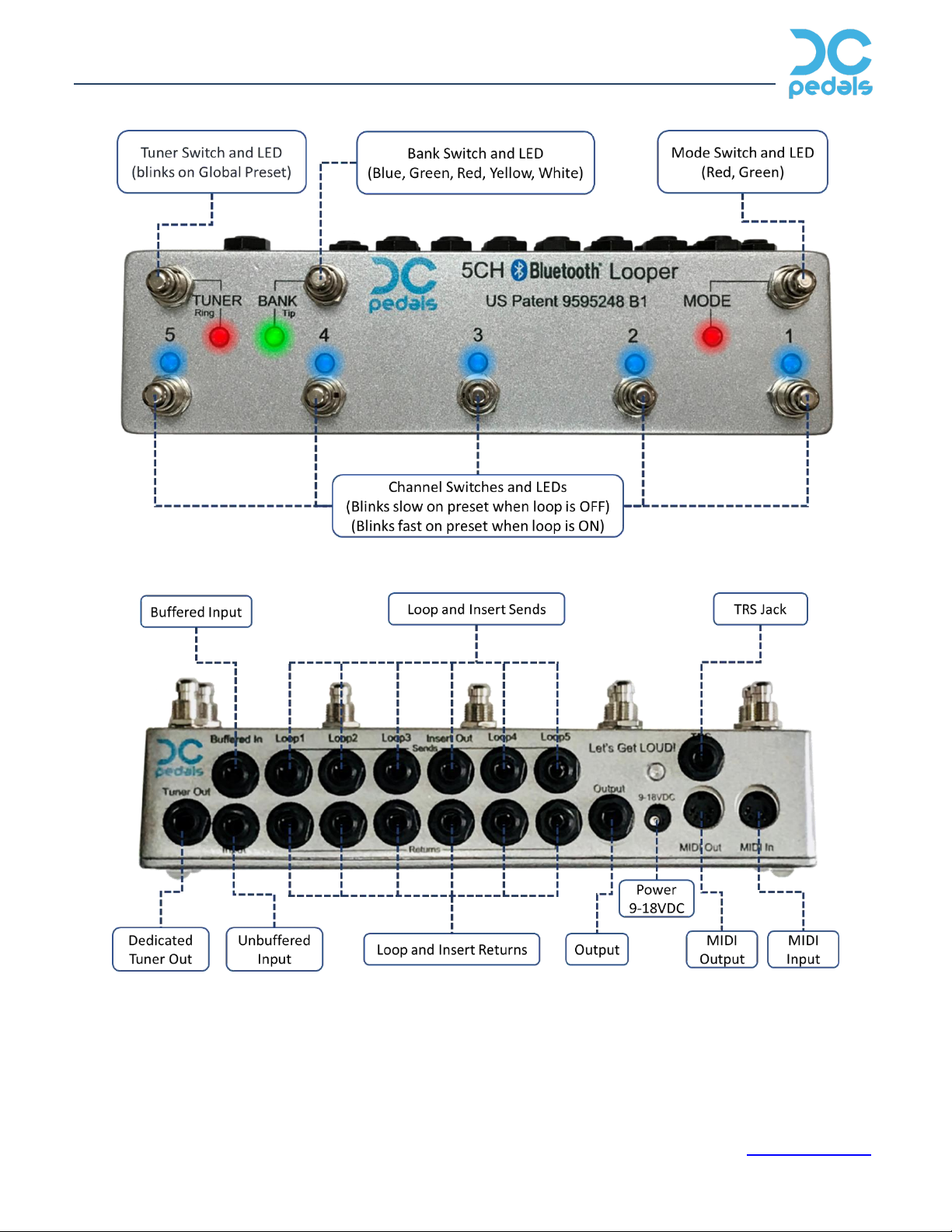
Top View –Switches and LEDs
Back View –Jacks
Mode Switch:
Push and release the Mode switch to toggle the looper between Live and Preset Modes. Hold the Mode
switch for 2 seconds to enter Programming Mode. While in Programming Mode hold the Mode switch for 2
seconds to enter Save Mode. See the Programming section to learn how to create and save presets. When
switching between Live and Preset modes, the looper retains the current state of the loops and just changes

5-Channel Bluetooth Looper –User Manual
©2019 DC Pedals. All Rights Reserved. r3.1 Page 4 of 12 www.dcpedals.com
the operation of the footswitches for the new mode. This feature enables you to “play out” of a preset and
make real-time adjustments to your tone if the song flow or set changes. Then with a quick press of the
Mode switch and a Channel switch and you are right back into the preset. This one-button Live Mode feature
is available only in DC Pedals designed loopers.
Bank Switch:
The Bank switch is active in both Live and Preset Modes but behaves differently in each mode. In Preset
Mode, pressing the Bank switch will cycle through the five banks of presets. An RGB LED shows the active
Bank. The color indicators are Blue (1), Green (2), Red (3), Yellow (4), and White (5). There are five Presets
in each Bank.
To change the current Folder, hold the Bank switch for 2 seconds. Loop LEDs 1-4 will light and the currently
selected folder will blink. Press Channel switch 1-4 to select a Folder. The corresponding LED will blink after
the Folder is selected. Also, the corresponding Folder LED will blink each time the Looper is powered ON.
In Live Mode, pressing the Bank switch activities the TIP function on the TRS jack. The TRS functions can be
latching or momentary.
The Tuner Switch:
The Tuner switch is similar to the Bank switch in that it behaves differently in Preset and Live Modes. In
Preset Mode, pressing the Tuner switch mutes the audio at both the input and output of the loops. This stops
any stray audio from getting into your delays and reverbs and keeps your amp quiet. The audio is still sent
through a buffer and to the Tuner-Out jack.
In Live Mode, pressing the Tuner switch activities the RING function on the TRS jack. The TRS functions can
be latching or momentary.
The Tuner switch can be changed to a Bank Down switch by holding the Tuner switch in Preset Mode. This
setting is retained during power cycles.
Channel Switches:
In Live Mode, the Channel switches toggle the corresponding loop on or off. In Preset Mode, the Channel
switches recall the saved preset stored in that preset/bank/folder. In Save Mode the Channel switch will
store the current setting (preset) into that preset, bank, and folder.
To access the TRS TIP function in Preset Mode, press switches 1 & 2 at the same time. LED 4 will blink to
confirm the TIP action. To access the TRS RING function in Preset Mode, press switches 2 & 3 at the same
time. LED 5 will blink to confirm the RING action.
Live Mode:
When in Live Mode, the looper operates just like a traditional true-bypass looper. Each Channel switch
toggles the corresponding loop on/off. The Mode LED is Green when the looper is in Live mode. The Bank
switch activates the TRS TIP function and the Tuner switch activates the TRS RING function.
Preset Mode:
When in Preset Mode, you can use any Channel switch to control any combination of loops. The Channel
switches set the looper to a Preset. A Preset is simply a definition of active loops and TRS functions. No

5-Channel Bluetooth Looper –User Manual
©2019 DC Pedals. All Rights Reserved. r3.1 Page 5 of 12 www.dcpedals.com
presets are created at the factory. It is important to know that the LEDs indicate which preset is active and
which loops are active. After selecting a Preset, the LEDs will light solid for the loops that are ON. The LED
associated with the selected Preset will blink fast if the loop is ON, or will blink slow if the loop is OFF. Note
that the loops are wired in sequential order, meaning loop 1 feeds into loop 2 which feeds into loop 3, etc.
Changing the order of the loops in a preset is not supported. We also include an Insert jack between Loops 3
and 4. This insert may be used many different ways, including using it to configure Loops 4 & 5 in amp
effects loops.
Programming Mode –Creating Presets:
Hold the Mode switch for 2 seconds to enter the Programming Mode. When in Programming Mode, the Mode
LED will blink slow. The looper will operate like it is in Live Mode with each Channel switch toggling the
corresponding loop. The Bank switch is active in Programming Mode and operates the same as in Preset
mode except Folder selection. Changing Folders in Programming Mode is not supported so make sure you
select the correct Folder prior to entering Programming Mode. Use the Channel switches to set the desired
loops. Once you have the desired loops set, press and hold the Mode switch again for 2 seconds. The looper
will enter Save Mode. The Mode LED will blink fast and the Channel LEDs will chase. If during Programming
Mode you press the Mode switch but don’t hold it, the looper will cancel the programming and go back to
where it was before you entered Programming Mode.
Save Mode –Saving Presets:
After the looper is in Programming Mode and you have the looper set to the desired preset, press and hold
the Mode switch for 2 seconds to enter Save Mode. In Save Mode, the Mode LED will blink fast and the
Channel LEDs will chase. If you want to save the preset to a new bank, press the Bank switch until the
desired bank is shown by the Bank LED. (Changing Folders in Save Mode is not supported.) Then press and
release any Channel switch to save the loops to that Preset/Bank. The LEDs will blink once to confirm the
save, and the looper will return to Preset Mode with the saved preset active. Pressing the Mode switch while
in Save Mode will cancel the Programming and the looper will return to the state before programming. The
LEDs will blink three times if the save is cancelled.
MIDI Program Change Messages:
By default, the looper sends a MIDI Program Change on the MIDI Output Channel every time a new preset is
selected. The MIDI PC message contains the same preset number as the looper. Presets are sequential
through the banks. Preset 1 in Bank 1 sends MIDI PC number 0. Preset 2 in Bank 1 sends MIDI PC number 1,
and so on. Preset 1 in Bank 2 sends MIDI PC number 5 … Preset 5 in Bank 5 in Folder 4 sends MIDI PC
number 99. The Global Preset sends MIDI PC number 127. The looper can be configured to NOT send a MIDI
PC message on certain presets. To access this option, see the Configuration section.
The VirtualLooper app can be used to send any value MIDI PC (valid values are 0-127) with each preset. This
feature can be used to better manage presets within the entire pedalboard. For example, preset 4 may recall
preset 22 in the Delay and Reverb pedals and preset 9 can also recall preset 22 in the Delay and Reverb
pedals. This MIDI PC map is saved in the bypass looper and will be reset during a Factory Reset.
The looper responds to MIDI PC messages from other devices. Any MIDI PC message received on the MIDI
Input Channel with a preset value of 0 through 99 will recall the corresponding looper preset (1-100). The

5-Channel Bluetooth Looper –User Manual
©2019 DC Pedals. All Rights Reserved. r3.1 Page 6 of 12 www.dcpedals.com
MIDI CC ID Description Values
70
Control Loop 1
0-63 Loop is OFF
64-127 Loop is ON
71
Control Loop 2
0-63 Loop is OFF
64-127 Loop is ON
72
Control Loop 3
0-63 Loop is OFF
64-127 Loop is ON
73
Control Loop 4
0-63 Loop is OFF
64-127 Loop is ON
74
Control Loop 5
0-63 Loop is OFF
64-127 Loop is ON
75
Control TRS TIP
0-63 TIP is OFF
64-127 TIP is ON
76
Control TRS RING
0-63 RING is OFF
64-127 RING is ON
77
Control Tuner
0-63 Tuner is OFF
64-127 Tuner is ON
78
Remote Save 0-100 Saves current setting to preset
82
State Set
Sets the state of
the loops and TRS
in once MIDI CC
message
Binary map of the Loops state. Bitwise
field with bits:
0 = MIDIPCFlag
1 = Loop1
2 = Loop2
3 = Loop3
4 = Loop4
5 = Loop5
6 = TRS Tip
7 = TRS Ring
8 = Must be zero!
MIDI CC Messages
Bank and Folder will be set automatically according to the received preset number. The looper will
automatically be set to Preset Mode after receiving a MIDI PC message.
MIDI Control Change Messages:
The Looper will respond to MIDI CC
messages sent on the MIDI Input Channel.
The Loops and TRS functions can be
controlled as well as remote saving of a
preset. See the table below for the CC IDs
and responses. Response to MIDI CC
messages can be turned off via the MIDI CC
Receive configuration parameter in the
Looper configuration pages. See the
Configuration section for more
information.
Looper Mute:
The mute feature is OFF after the Factory
Reset. If there are significant pops or
noises while switching loops, activate the
Mute feature to reduce the noises.
However, some audio signal is lost when
the Mute is ON. The short mute time is
about 7ms and the long time is about
24ms. Choose the shortest time that
reduces the noises.
Looper Configuration:
There are many configuration options to configure the Looper for your needs. The configuration pages are
accessed during power-up. To access the configuration pages, hold the Mode switch during power-up. The
Mode LED will toggle while the switch is held. Release the switch and the Looper will enter Configuration
Mode. While in Configuration Mode, the Mode LED indicates the active configuration page. There are five
configuration pages. Press the Mode switch to cycle through the five configuration pages.

5-Channel Bluetooth Looper –User Manual
©2019 DC Pedals. All Rights Reserved. r3.1 Page 7 of 12 www.dcpedals.com
Mode LED Indicates Config Page - Green
Mode Switch
Press to advance Config Page
Hold to save and restart
Bank LED Indicates Bank
Bank Switch
Press to advance Bank
Hold to select Folder
Channel LED 1
MIDI PC Flag for this preset
ON = MIDI PC message will be sent
OFF = MIDI PC will NOT be sent
Channel SW 1 Toggles MIDI PC Flag for this preset
Channel LED 2
MIDI PC Flag for this preset
ON = MIDI PC message will be sent
OFF = MIDI PC will NOT be sent
Channel SW 2 Toggles MIDI PC Flag for this preset
Channel LED 3
MIDI PC Flag for this preset
ON = MIDI PC message will be sent
OFF = MIDI PC will NOT be sent
Channel SW 3 Toggles MIDI PC Flag for this preset
Channel LED 4
MIDI PC Flag for this preset
ON = MIDI PC message will be sent
OFF = MIDI PC will NOT be sent
Channel SW 4 Toggles MIDI PC Flag for this preset
Channel LED 5
MIDI PC Flag for this preset
ON = MIDI PC message will be sent
OFF = MIDI PC will NOT be sent
Channel SW 5 Toggles MIDI PC Flag for this preset
Configuration Page 1 - MIDI PC Flags

5-Channel Bluetooth Looper –User Manual
©2019 DC Pedals. All Rights Reserved. r3.1 Page 8 of 12 www.dcpedals.com
Mode LED Indicates Config Page - Red
Mode Switch
Press to advance Config Page
Hold to save and restart
Bank LED OFF
Bank Switch
No action
Channel LED 1
TRS TIP function
ON = Latching
OFF = Momentary (100ms pulse)
Channel SW 1 Toggles TRS TIP function
Channel LED 2
TRS RING function
ON = Latching
OFF = Momentary (100ms pulse)
Channel SW 2 Toggles TRS RING function
Channel LED 3
Audio mute function
OFF = Mute OFF when switching loops
Blinking Fast = Mute ON short time when switching loops
Blinking Slow = Mute ON long time when switching loops
Channel SW 3 Toggles audio mute OFF->Short->Long-.OFF
Channel LED 4
MIDI Through Flag
ON = MIDI Through enabled
OFF = MIDI Through disabled
Channel SW 4 Toggles MIDI Through
Channel LED 5
MIDI CC Receive Flag
ON = MIDI CC receive enabled
OFF = MIDI CC receive disabled
Channel SW 5 Toggles MIDI CC Receive Flag
Configuration Page 2 - TRS Mode, MIDI Through Enable, MIDI CC Receive Enable
5-Channel Bluetooth Looper –User Manual
©2019 DC Pedals. All Rights Reserved. r3.1 Page 9 of 12 www.dcpedals.com
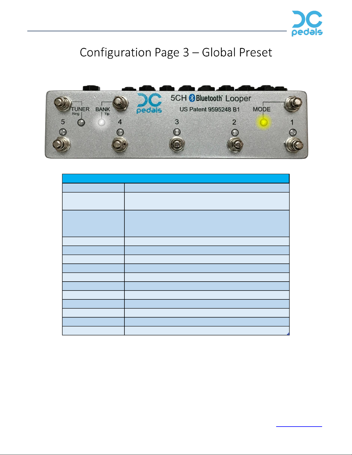
Mode LED Indicates Config Page - Green + Red
Mode Switch
Press to advance Config Page
Hold to save and restart
Bank LED
MIDI PC Flag for global preset
ON = MIDI PC message will be sent
OFF = MIDI PC will NOT be sent
Bank Switch
Toggles MIDI PC Flag for global preset
Channel LED 1
Loop 1
Channel SW 1 Toggles Loop 1
Channel LED 2
Loop 2
Channel SW 2 Toggles Loop 2
Channel LED 3
Loop 3
Channel SW 3 Toggles Loop 3
Channel LED 4
Loop 4
Channel SW 4 Toggles Loop 4
Channel LED 5
Loop 5
Channel SW 5 Toggles Loop 5
Configuration Page 3 - Global Preset

5-Channel Bluetooth Looper –User Manual
©2019 DC Pedals. All Rights Reserved. r3.1 Page 10 of 12 www.dcpedals.com
Mode LED
Indicates Config Page - slow blink
Mode Switch
Press to advance Config Page
Hold to save and restart
Bank LED
OFF
Bank Switch
No action
Channel SW 1
Toggles bit 1
Channel SW 2
Toggles bit 2
Channel SW 3
Toggles bit 3
Channel SW 4
Toggles bit 4
Channel SW 5
No action
Binary MIDI Input Channel
Channel LED 1
Channel LED 2
Channel LED 3
Channel LED 4
Channel LED 5
Configuration Page 4 - MID Input Channel

5-Channel Bluetooth Looper –User Manual
©2019 DC Pedals. All Rights Reserved. r3.1 Page 11 of 12 www.dcpedals.com
Mode LED
Indicates Config Page - fast blink
Mode Switch
Press to advance Config Page
Hold to save and restart
Bank LED
OFF
Bank Switch
No action
Channel SW 1
Toggles bit 1
Channel SW 2
Toggles bit 2
Channel SW 3
Toggles bit 3
Channel SW 4
Toggles bit 4
Channel SW 5
No action
Channel LED 1
Channel LED 2
Channel LED 3
Channel LED 4
Channel LED 5
Binary MIDI Output Channel
Configuration Page 5 - MID Output Channel

5-Channel Bluetooth Looper –User Manual
©2019 DC Pedals. All Rights Reserved. r3.1 Page 12 of 12 www.dcpedals.com
Factory Reset:
To restore the looper to factory settings, power OFF the looper. Then press and hold the Mode switch AND
the Channel 1 switch and apply power. Make sure you hold both switches during power-up. The Mode LED
will toggle until you release both switches. Release the switches and the Mode LED will toggle faster. Then
press the Mode switch again to reset the looper. WARNING: All the user memory will be erased and set to
factory settings, including the MIDI PC settings. The looper will automatically restart with factory settings.
To cancel the factory reset, remove power and restart the looper normally.
DC Pedals is located in Florida and can be reached at www.dcpedals.com. All DC Pedals products are
designed and manufactured in the USA! Thanks for your business.
Table of contents


