Instruct the staff on the use of this machine with the operators instructions provided
(see overleaf)
Preparing the location & machine
• Verify the intended or existing electrical connections agrees with the specifications on the machine id. plate located on the right side panel of the machine.
• Check the machine and stand (if supplied) will fit in/under the location for installation.
• Clear the location where the machine will be installed, remove any unused tubes or redundant plumbing that will not be used for the new installation.
• Clear a location for the Detergent & Rinse aid chemicals (as close to the machine as possible, this can be to the left or right).
• Remove any redundant wiring (if removing old machine) WARNING! be sure the electrical power has been turned off at the breaker/main fuse box.
• Remove the protective plastic covering from the machine & keep the packaging materials and pallet until the installation is complete.
Water supply
• Place the machine near to the location (allowing room behind the machine to connect the water and waste hoses).
• Connect the mains cold water hose 3/4 BSP (supplied) from the machine to a mains water shut off tap (not supplied). This shut off tap should already be
fitted to the existing plumbing on site.
• If connecting a water softener use an extra mains cold water hose to connect from the machine to the softener and then to the mains water shut of tap.
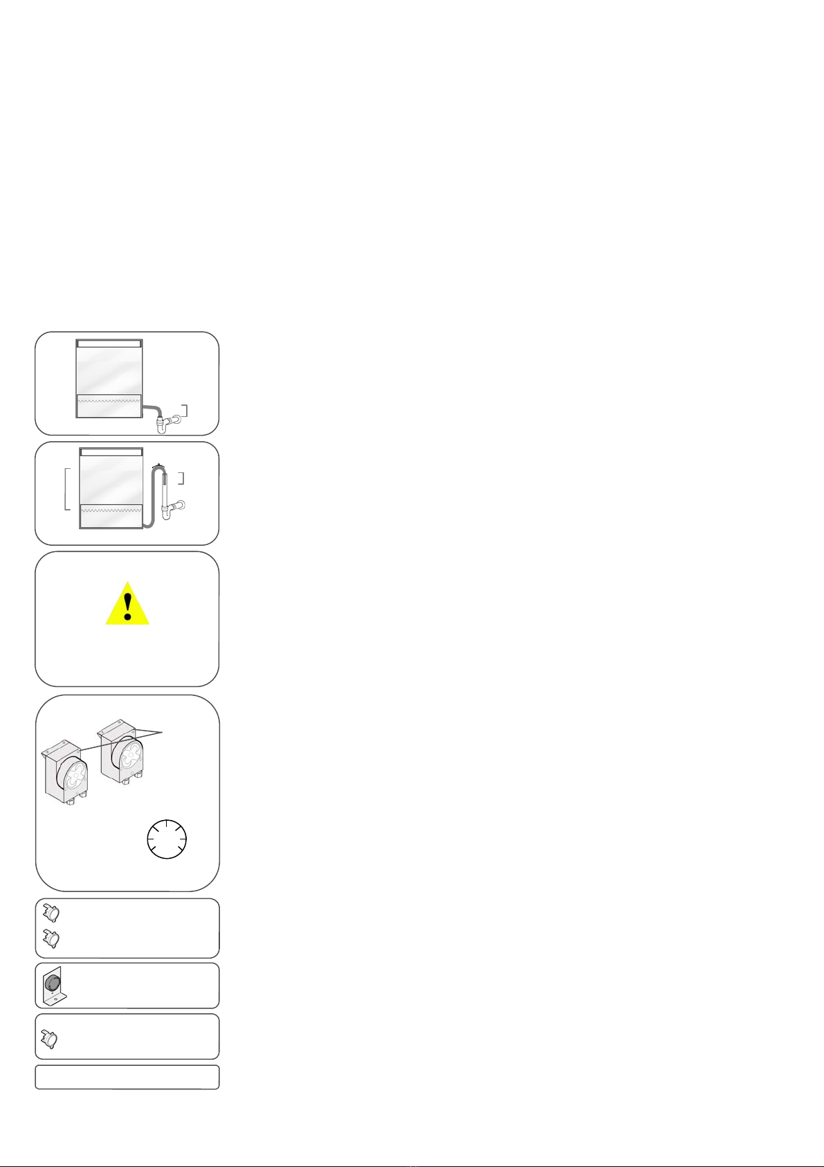
Gravity waste
• Connect the waste hose directly into the waste outlet. This can be sealed into the pipe.
• A “running trap ” or “P trap” must be used to prevent odours returning into the machine.
• The hose can be shortened but enough slack should be left to allow the machine to be pulled out for servicing.
• The waste outlet “running trap ” or “P trap” level should be around 100mm below the water level inside the machine
to allow proper drainage.
• Make sure drain hose is kink-free and not liable to be crushed when the machine is pushed into place.
Pumped waste
• Connect the waste hose directly into the waste stand pipe. This should be approximately 400mm above the water
level inside the wash tank of the machine.
• Insert the waste hose into the stand pipe using the high loop hook. (supplied).
• Do not seal the waste hose into the stand pipe, this must be plumbed as an “open to air “ connection.
• A “running trap ” or “P trap” should be used to prevent odours returning into the machine.
• Make sure drain hose is kink-free and not liable to be crushed when the machine is pushed into place.
Electrical connections
• Connect the mains cable supplied with the machine to the 13amp socket or hard wire into 25amp or three phase
supply 16amps per phase as required by the machine specifications.
• Electrical supply 25amp or three phase supply must be connected by a qualified electrician or catering engineer
trained for this type of machine. There should be a suitably rated mains on/off switch fitted close to the machine.
Detergent and Rinse aid dosing pump priming and adjustment
• Remove the lower front panel of the machine to access the peristaltic dosing pump.
• Check the red detergent tube & clear rinse aid tubes do not fowl the cooling fan on the waste pump (if fitted).
• As the wash tank fills with water turn both adjustments to maximum temporarily to prime the machine with chemicals.
• Reduce the detergent adjustment to (3 - 5) test the washing results and increase the adjustment if necessary.
• Reduce the rinse aid adjustment to (1 - 2) test the washing results and increase the adjustment if necessary.
• As a guide only allow 4mm to 6mm of foam to be visible on the wash tank water surface at the end of a wash cycle.
WARNING! Failure to adjust the peristaltic dosing pump correctly will result in poor results or damage to the machine.
Too much rinse aid can result in foaming and cause cloudiness or streaks on glasses or dishes.
Hard water conditions will adversely affect washing performance and cause spotting on glasses or dishes.
To maximize the performance of the machine it is recommended that a water softener be fitted to improve the
detergent and rinse aid results and eliminate lime scale build up inside the machine.
Chemical products & suppliers may vary in the concentration and quality of there detergent and rinse aid, it is
important that adjustment are made with this taken into consideration. Changing supplier or concentration of the
chemicals used in the future may need new adjustments to be made to the dosing pump.
DC SERIES WARE WASHING INSTALLATION AND COMMISSIONING GUIDE
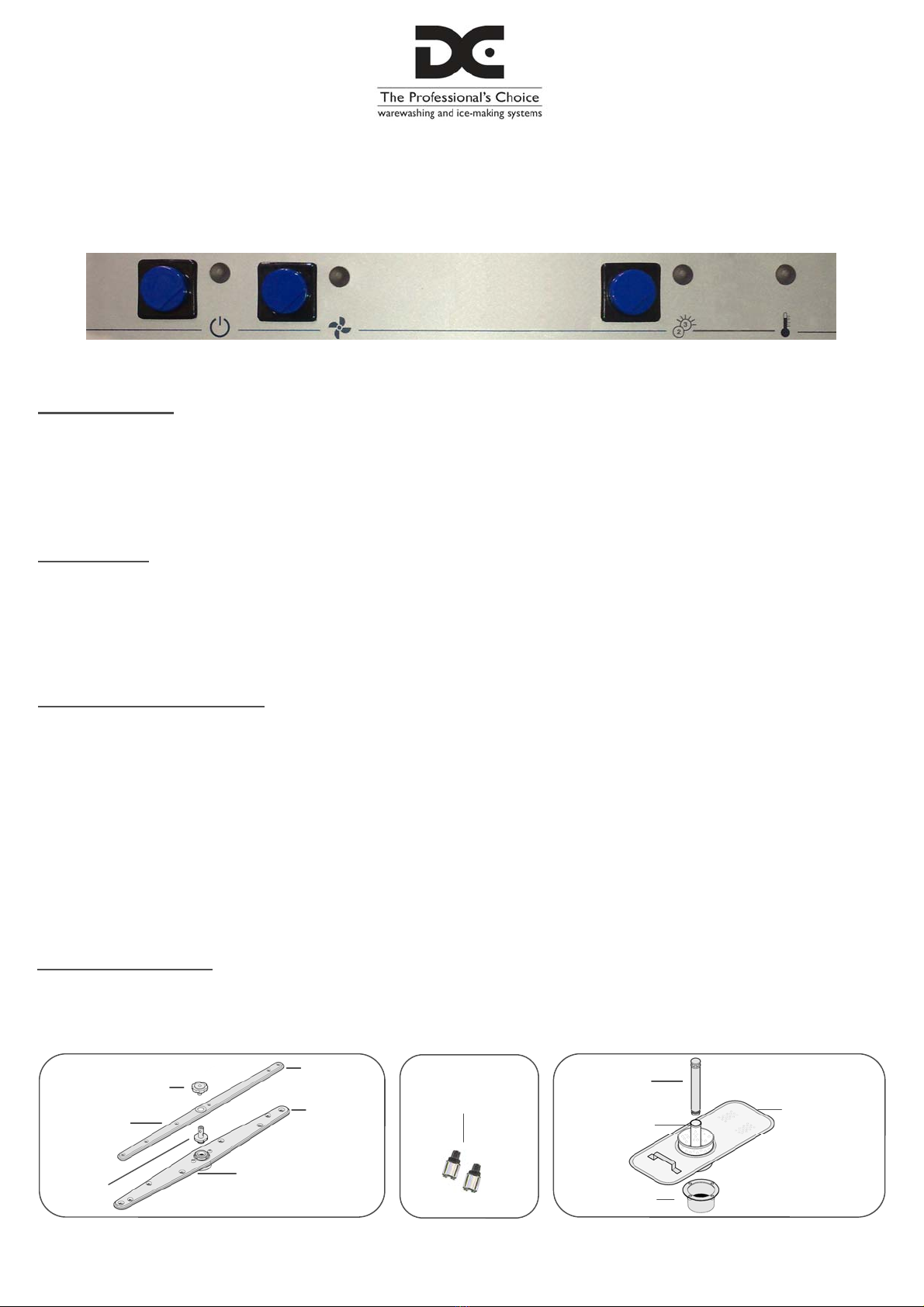
Pre-test
• Turn on the water supply to the machine and check for any leaks. Turn on the mains power supply and then the
machine on/off switch, the wash tank will start to fill and the boiler will begin to heat. The boiler amber lamp will go
out when the adjusted boiler temperature is reached (see commissioning the machine).
Peristaltic dosing pumps adjustment
Commissioning the machine
• Adjust the rinse boiler temperature dial to 86c or as required. The wash tank thermostat will be factory set to 60c.
• Run through several cycles, the machine will wash and then move onto the rinse part of the cycle before finishing.
• Check for waste pump (if fitted) & dosing pump activation at the end of each cycle.
• Check temperatures for the rinse boiler and wash tank. Run several full basket loads through the machine and study
the results at the end of the wash cycle, adjust dosing pumps or temperatures accordingly.
• The machine ready lamp is connected to an independent surface thermostat fitted to the wash tank set at 42c
Thermostop boiler rinse facility activated by connecting P7 on the pcb timer from 240v from the boiler thermostat output.
The machine will start washing and calculate the cycle lenghth and continue onto rinse when boiler temp high.
WARNING
Removing the lower front or top panel
will expose an electric shock risk.
Installation and servicing must be carried
out by qualified catering engineers trained
for this type of machine.
Gravity waste
100mm
Pumped waste
400mm 100mm
General safety regulations
• The following installation procedures have been produced in conjunction with the user instructions and safety regulations book supplied with this machine.
• Installation and servicing must be carried out by qualified catering engineers trained for this type of machine.
• Earth bonding must be fitted to the lower rear bonding point of the machine and any tables and sinks connected to the machine.
• Direct Catering Products Ltd. will not be liable for any harm or injury, to property or persons, or consequences of incorrect installation or servicing.
Min Max
1
2
345
6
7
Adjustments
Rinse aid
(Clear tube)
Detergent
(Red tube)
Wash tank surface- thermostat
60c Normally closed
Rinse boiler thermostat
Adjustable 0 - 90c
Safety overload surface thermostat
110c Normally closed
Wash tank fitted surface thermostat
42c connected only to the machine
ready lamp - Normally open
Thermostop boiler controlled