LG LD-4050W User manual

P/No. : 3828ED3001L

DISHWASHER
SERVICE MANUAL
BEFORE SERVICING THE UNIT, PLEASE READ THIS MANUAL CAREFULLY
FOR SAFETY AND CORRECT SERVICES.
NOTE
MODEL : LD-4050W
LD-14AW2, LD-14AT2

- 3 -
1. CAUTION....................................................................................................................................4
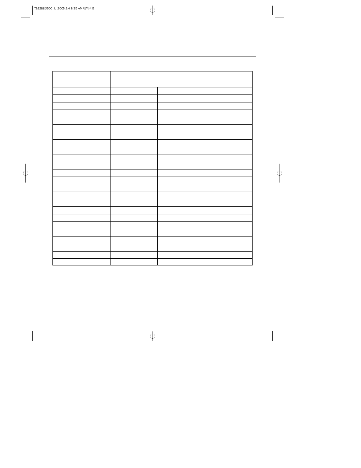
2. SPECIFICATIONS.....................................................................................................................5
3. FEATURES & TECHNICAL EXPLANATION.....................................................................6
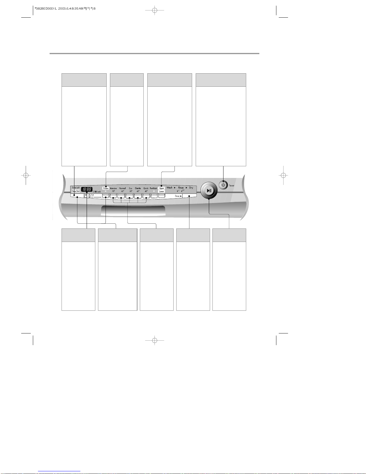
4. PARTS NAME.........................................................................................................................11
5. WIRING DIAGRAM...........................................................................................................13
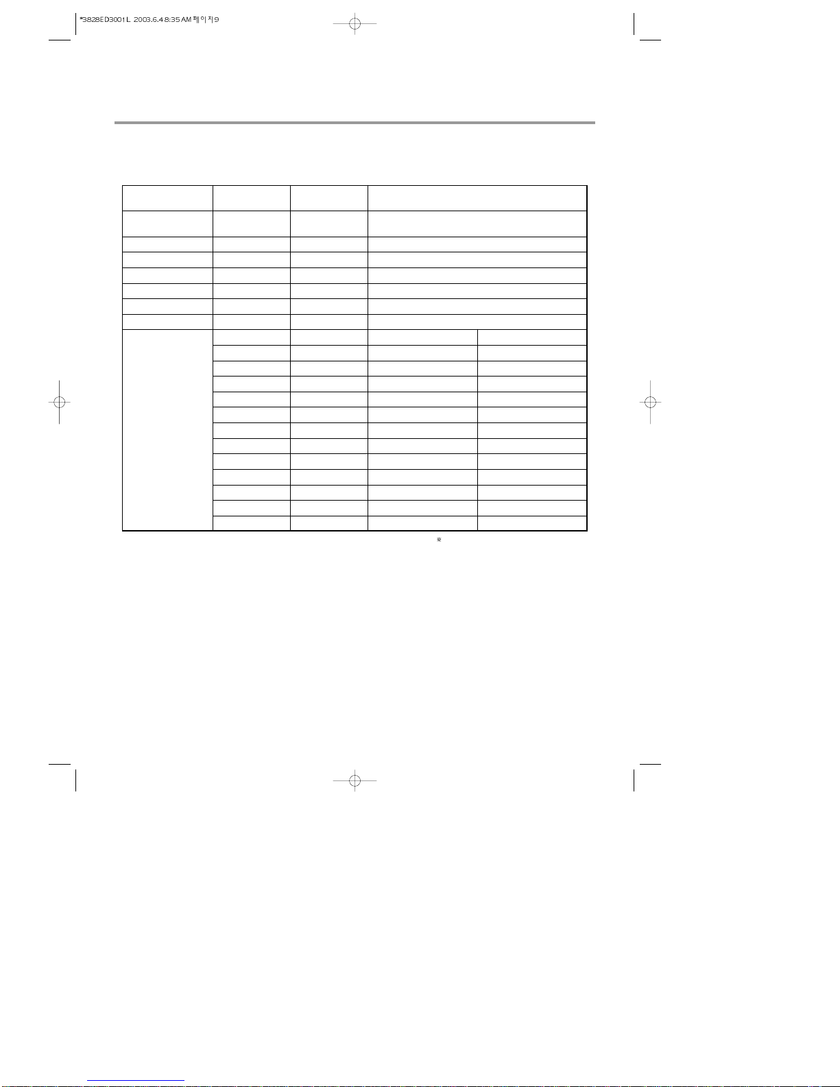
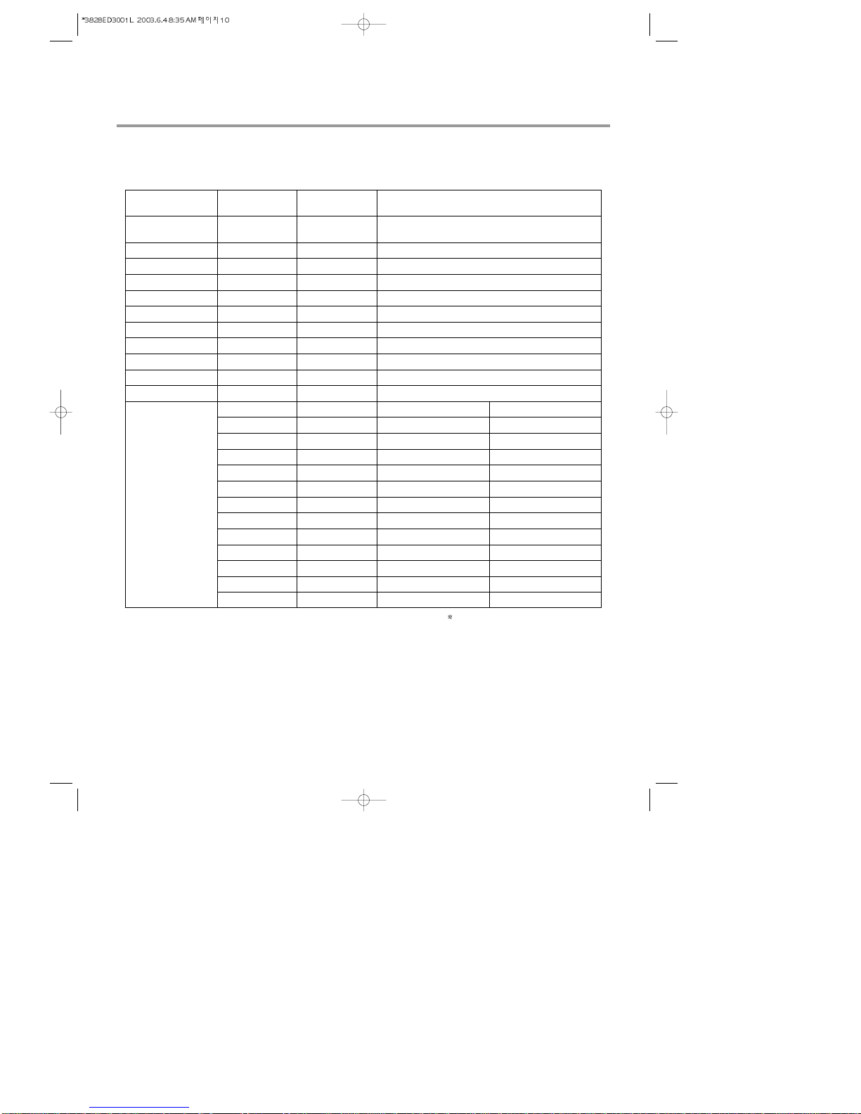
6. PROGRAM CHART (SCHEMATIC DIAGRAM)............................................................15
7. HOW TO DISASSEMBLE ...................................................................................................17
8. TROUBLE SHOOTING METHODS.....................................................................................27
A. TROUBLE SHOOTING ACCORDING TO DISPLAYED ERROR MESSAGE.........27
B. TROUBLE DIAGNOSES AND REPAIR BY SYMPTOM ..........................................29
9. INSTALLATION INSTRUCTION.....................................................................................33
10. EXPLODED VIEW ..............................................................................................................38
11. REPLACEMENT PART LIST............................................................................................44
CONTENTS

- 4 -
�DISCONNECT POWER CORD BEFORE SERVING
�RECONNECT ALL GROUNDING DEVICES
IMPORTANT SAFETY NOTICE !
This service information is intended for individuals
possessing adequate backgrounds of electrical,
electronic and mechanical experience.
Any attempt to repair this appliance may result in
personal injury and property damage.
The manufacturer or seller can not be responsible
for the interpretation of this information, nor can it
assume any liability in connection with its use.
CAUTION !

- 5 -
2. SPECIFICATION
Model
Rated Voltage / Frequency
Installation
Place Settings
Product Dimension(mm)
Product Weight(Kg)
Door Colour
Tub Material
Control
Rated Power(Watt)
Heater Power(Watt)
Programs
Upper Rack Position
Lower Rack
Water Consumption(ℓ)
Power Consumption (kWh)
Operating Time (min)
Fan Dry System
Delay Start Function
Auto-Off Power Switch
Process Monitor
Wash Level
Racks
Operating Water Pressure (Bar)
ITEM SPECIFICATION
LD-4050W LD-14AW2LD-14AT2
AC 240V/50Hz
Free Standing / built-In
14
600(W)×600(D)×850(H)
52
Stainless Steel
Stainless Steel
Electronic
2,210
2,100
6
Sliding Adjustable
100% Fold down
18 (Economy)
0.7 (Economy)
84 (Economy)
Yes
Yes
Yes
Yes
5
Nylon Coating
0.5 ~ 8
AC 240V/50Hz
Free Standing / built-In
14
600(W)×600(D)×850(H)
52
White
Stainless Steel
Electronic(Fussy)
2,210
2,100
6
Sliding Adjustable
100% Fold down
18 (Economy)
0.7 (Economy)
84 (Economy)
Yes
Yes
Yes
Yes
5
Nylon Coating
0.5 ~ 8
AC 240V/50Hz
Free Standing / built-In
14
600(W)×600(D)×850(H)
52
White
Stainless Steel
Electronic
2,210
2,100
6
Adjustable
50% Fold down
18 (Economy)
0.7 (Economy)
84 (Economy)
Yes
Yes
Yes
Yes
5
Nylon Coating
0.5 ~ 8

- 6 -
3. FEATURES & TECHNICAL EXPLANATION
• Turbo fan drying system expels out hot and
humid air to enhance quick and effective
drying.
3-1 New Technology Introduction
3-1-1. Turbo Fan Drying System
• During the high temp. Rinse course, water
temperature in an dishwasher reaches 77°C,
considerably higher than the average rinse
temperature in conventional
dishwashers(65°C). This is how Rinse 77°C
can eliminate some bacteria such as
salmonella.
3-1-2. High Temperature Rinsing
• Turbo Spray System is elaborately designed to
achieve a more powerful and efficient wash.
You can see the excellent 3 rotating spray arm
with 5 directional waterjet.
3-1-3. Turbo Spray System

- 7 -
3-2. Display Panel
LD-4050W
RINSE /
EXTRA HOT
CHILD LOCK TIME DELAY SPRAY INTENSITY POWER
HALF LOAD DIAL (PROGRAM &
START / PAUSE) TIME SAVE

3-2. Display Panel
LD-14AW2 / LD-14AT2
- 8 -
• If you want to delay the
start of selected program,
press this button before
pressing start button.
• Pressing the delay time
will increase time by
1 hour.
• The delay start time can
be adjusted from 1 hour
to 19 hours.
DELAY START
BUTTON
• This function is
for saving time
and energy.
• With each press,
time save ON and
OFF is repeated.
• When select this
function, the
operating time will
be shorten.
TIME SAVE
• For operating, press this
button first for power on.
• After operating, this button
automatically switches off for
safety and energy saving.
• If case of irregular surge
disturbances to the machine,
the power may be
automatically turned
off for safety.
POWER SWITCH
BUTTON
• In case of small load, use
upper or lower rack only
to save energy.
• With each press, can
select upper or lower rack
only.
• In case you don’t select
this button, the machine
always works vario
washing, which operate
upper and lower spray
arm alternately.
HALF LOAD
• Indication of
remaining time
• Self diagnosis
and error
message display
REMAINING
TIME
• Used to lock or
unlock the control
buttons to prevent
all the setting from
being changed by a
child.
• For
locking/unlocking,
press Delay Start
and T-Save button
simultaneously.
CHILD LOCK
• When power is
on, program is
automatically set
to normal.
• If you want to
change the
program, press
the button and
set the program
you want to.
PROGRAM
• With each press,
Start and Pause
is repeated
during
operation.
• If the machine
remains in
Pause mode for
10 minutes, the
power is
automatically
turned off.
START/PAUSE
BUTTON
• With each press,
rinse+, rinse+ &
77。C sani rinse,
77。C sani rinse
is repeated.
RINSE/SANI

3.3 TEST MODE
CHECK PROGRAM(START IN THE STATE OF THE CLOSED DOOR)
- 9 -
LD-4050W
BUTTON The number of
pushing button DISPLAY Load and Checking points
Half Load+Time
Delay+POWER S/W
Rinse
Half Load
Time Delay
Multi Spray
Time Save
Dial knob
Start/Pause
1 TIME
1 TIME
1 TIME
1 TIME
1 TIME
1 TIME
1 Rotation
1 TIME
2 TIME
3 TIME
4 TIME
5 TIME
6 TIME
7 TIME
8 TIME
9 TIME
10 TIME
11 TIME
12 TIME
13 TIME
n : 0H
11 : 11
12 : 22
13 : 33
14 : 44
15 : 55
11 : 11 ~ 16 : 66
n : 01
Frequency
n : 03
n : 04
n : 05
n : 06
n : 07
n : 08
n : 09
Temperature
n : 11
n : 12
All LEDs are lighting
The LED of each course is lighting
None
Water level sensor
Washing motor
Drain pump
Inlet valve
Dispenser
Heater(for 10 sec.)
Fan motor
None
Thermister
Lower Nozzle
Upper Nozzle
Intensive
Auto
Economy
Gentle
Quick
Pre-wash
Time Save
Wash
Rinse
Dry
Lower
Upper
AUTO OFF S/W
Micro S/W must be ON to operate HEATER

3.3 TEST MODE
CHECK PROGRAM(START IN THE STATE OF THE CLOSED DOOR)
BUTTON The number of
pushing button DISPLAY Load and Checking points
Normal+Eco
+POWER S/W
Delay Start Key
T-Save Key
Intensive Key
Normal Key
Eco Key
Gentle Key
Quick Key
Pre-Wash Key
Half & Vario Key
Rinse Key
Start/Pause
1 TIME
1 TIME
1 TIME
1 TIME
1 TIME
1 TIME
1 TIME
1 TIME
1 TIME
1 TIME
1 TIME
1 TIME
2 TIME
3 TIME
4 TIME
5 TIME
6 TIME
7 TIME
8 TIME
9 TIME
10 TIME
11 TIME
12 TIME
13 TIME
n : 0H
11 : 11
12 : 22
13 : 33
14 : 44
15 : 55
11 : 11 ~ 16 : 66
17 : 77
18 : 88
19 : 99
10 : 00
n : 01
Frequency
n : 03
n : 04
n : 05
n : 06
Temperature
n : 07
n : 08
n : 09
n : 11
n : 12
All LEDs are lighting
None
Water level sensor
Washing motor
Drain pump
Inlet valve
Dispenser
Heater(for 10 sec.)
Fan motor
None
Thermister
Lower Nozzle
Upper Nozzle
Time Save
Intensive
Normal
Eco
Quick
Pre-wash
Wash 1
Wash 2
Rinse 1
Rinse 2
Dry
AUTO OFF S/W
Micro S/W must be ON to operate HEATER
LD-14AT2/LD-14AW2
- 10 -

Inlet Hose
1. Control Panel
2. Vapor vent
3. Door Handle
4. Front Cover
5. Lower Cover
6. Process Monitor
7. Power Switch
8. Drain hose
9. Inlet valve ASM
10. Power Cord
11. Adjust Leg
12. Upper Rack
13. Cutlery Rack
14. Detergent & Rinse Aid Dispenser
15. Vapor Vent Cover
16. Upper Spray Arm
17. Lower Spray Arm
18. Filter ASM
19. Lower Rack
- 11 -
4. PARTS NAME LD-4050W

Inlet Hose
1. Vapor vent
2. Control Panel
3. Door Handle
4. Front Cover
5. Lower Cover
6. Process Monitor
7. Power Switch
8. Inlet valve ASM
9. Drain Hose Connector
10. Power Cord
11. Adjust Leg
12. Upper Rack
13. Cutlery Rack
14. Detergent & Rinse Aid Dispenser
15. Vapor Vent Cover
16. Upper Spray Arm
17. Lower Spray Arm
18. Filter ASM
19. Lower Rack
4. PARTS NAME
- 12 -
LD-14AT2/LD-14AW2

- 13 -
5. WIRING DIAGRAM
LD-4050W

5. WIRING DIAGRAM
- 14 -
LD-14AW2
LD-14AT2

- 15 -
6. PROGRAM CHART(SCHEMATIC DIAGRAM)

6. PROGRAM CHART
(PGM TIME Flow-Default, Vario)
- 16 -

7-1. FULL DISASSEMBLE
BEFORE DISASSEMBLING THE DISHWASHER ;
1) Remove the plug from electric outlet to avoid electric shock.
2) Close the Water Tap(faucet).
3) Remove all dishes and items in the dishwasher.
4) Remove the Lower Rack and the Upper Rack.
5) If necessary, remove the inlet hose and drain hose to avoid the hose damages.
6) Prepare some towels to avoid floor wet by the water left in the dishwasher.
1. Top Table
1) Remove the rear 2 screws.
2) Pull and lift the top table.
2. Low Cover
3. Cabinet-R/L
1) Cabinet-R
Remove front 4 screws.
Remove rear 3 screws.
2) Cabinet-L
Remove front 4 screws.
Remove rear 3 screws.
- 17 -
7. HOW TO DISASSEMBLE

4. Balance weight
1) Remove side 4 screws.
2) Lift the balance weight.
5. Door Assembly
1) Front Cover
Open the door.
Remove 6 screws(stainless).
Close the door slowly and remove front
cover downwards.
2) Control Panel Assembly
Open the door.
Remove 4 screws(stainless).
Remove wire connection.
Be sure the wiring should not be
changed in reassembling.
Remove 3 screws for Latch assembly
Remove 5 screws for Controller.
LD-4050W
LD-14AW2
LD-14AT2
- 18 -

- 19 -
3) Fan
Open the door.
Remove the outer cover by removing 1
screw.
Remove 2 fixing screws inside and turn
the Inner Cover counterclockwise.
4) Detergent Dispenser
Close the door.
Remove the wire connections.
Remove 6 screws with brackets.
Detergent
Dispenser
Door Liner
Door Bracket
Inner
Cover
Out
Cover
Fan
Fan
5) Door Spring (Right & Left)
Push the Spring upwards and take it off
from the Frame.
Be careful not to be injured by the sharp
edge of Tub.
Take the Hinge Link off from the Hinge.
6) Door Liner
Open the door.
Remove 4 screws.
Do not use other screws for assembling.
LD-4050W, LD-14AT2
LD-14AW2

- 20 -
6. Base spacer
Remove 4 screws.
Lift the front side of dishwasher and pull
the base spacer forward.
7. Tub assembly
1) Nozzle
Pull up the nozzle.
2) Filter Assembly
Turn inner filter counterclockwise and lift
inner filter and middle filter.
You can disassemble inner filter and
middle filter by pulling opposite direction.
Lift up main filter.
Lift up micro filter.
3) Nozzle Holder
Disconnect the water guide
Remove 4screws and lift it up
Main filter
Inner filter
Middle filter
Micro filter
Other manuals for LD-4050W
1
This manual suits for next models
2
Table of contents
Other LG Dishwasher manuals

LG
LG D1451WLF User manual

LG
LG LDF6920WW User manual

LG
LG LDF7811 User manual

LG
LG LD1452WLFEN2 User manual

LG
LG D1485 Series User manual

LG
LG LDF9810ST - Fully Integrated 6 Wash Cycles... User manual

LG
LG DF6810WW User manual

LG
LG LDT566 SERIES User manual

LG
LG LDS 5811WW User manual

LG
LG D1455 series User manual

LG
LG LDS4821WW - Full Console Dishwasher User manual

LG
LG DF425 Series User manual

LG
LG LSDT990 Series User manual

LG
LG LDS5040BB Assembly instructions

LG
LG XD64 Series User manual

LG
LG D1427WLFB User manual

LG
LG LDS5540ST User manual

LG
LG LD-2160WH User manual

LG
LG LDS5540ST User manual

LG
LG LDF6810WW User manual