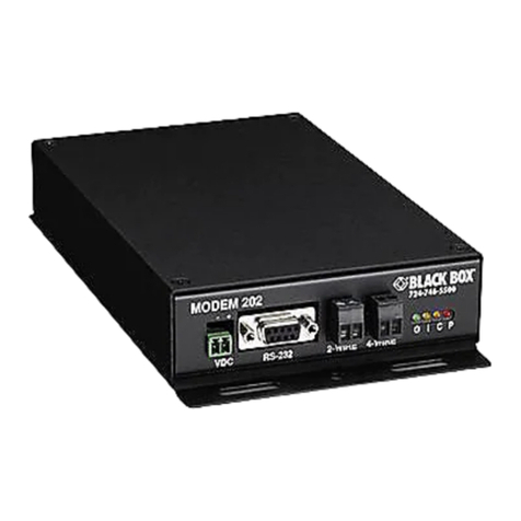
DCB V.23 User manual

8500123
V.23 ASYNC Modem
TABLE OF CONTENTS
SECTION 1 - DESCRIPTION ..........................................................................2
SECTION 2 - SPECIFICATIONS ....................................................................3
SECTION 3 - INSTALLATION ........................................................................ 5
SECTION 4 - CONTROLS AND INDICATORS ............................................ 6
SECTION 5 - INTERFACE SIGNALS AND CABLES .................................
SECTION 6 - TROUBLESHOOTING ............................................................ 8
SECTION - WARRANTY................................................................................9
NOTICE
The PC card modem meets the applicable Industry Canada Terminal
Equipment Technical Specifications. This is confirmed by the registration
number. The abbreviation IC before the registration number signifies that
registration was performed based on a Declaration of Conformity indicating
that Industry Canada technical specifications were met. It does not imply
that Industry Canada approved the equipment.
The RINGER EQUIVALENCE NUMBER (REN) for this terminal equipment
is Not Applicable. The REN assigned to each terminal equipment provides an
indication of the maximum number of terminals allowed to be connected to a
telephone interface. The termination of an interface may consist of any
combination of devices subject only to the requirement that the sum of the
Ringer Equivalence Numbers of all the devices does not exceed five (5.0).
Data Comm for Business Inc.
PO Box 6329
Champaign IL 61826-6329 October 23 2015
(217) 897-6600 Firmware Version: 1.8
www.dcbnet.com

2
1. DESCRIPTION
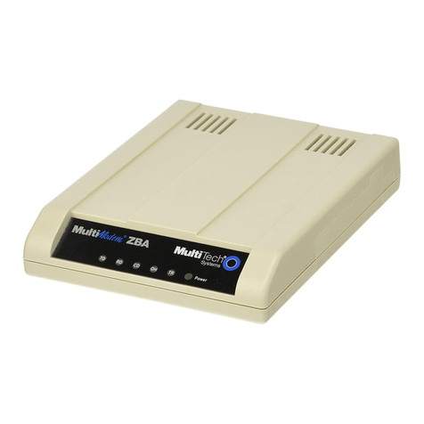
The V.23 modem operates at 0 to 1200 bps asynchronous with FSK
modulation. It uses the latest DSP modem circuitry to insure
excellent performance and future availability. It has 900 hz soft
carrier turn off for multidrop applications and an anti-streaming
option. Standalone and PC half card configurations are available.
The PC card uses the internal ISA bus for power and ground. The PC
card fits into a 20 slot rack mount chassis that is only 7” high. The
phone line connector is an RJ-11 for 2 wire or 4-wire leased line
operation. Transmit is on positions 3 and 4 receive 2 and 5 of the 6
position jack. For 2-wire operation a special cable configuration is
required (see Section 5).
The modem has DIP switch controls for reset anti-streaming phase
equalizer constant or controlled carrier soft carrier turn-off 2-wire
or 4-wire line transmit level and loopback. The modem also has a
pushbutton switch for local digital loopback. The DIP switches are
accessible from the front of the modem. A pushbutton loopback
switch is located on the rear of the unit.
TERMINAL TELCO POWER
LOOP 12VDC
V.23 ASYNC MODEM
POWER
TXD
R
XD
RTS
CTS
DCD
TEST

3
2. SPECIFICATIONS
2.1 Modem
Analog full duplex 4-wire 600 ohm balanced Frequency Shift Keying
Mark-1300 hertz Space-2100 hertz
Speed: 0 to 1200 bps ASYNC
Transmit level: 0 or -16 dBm
Receive range: 0 to - 42 dBm
Carrier turn-on time: less than 20 ms
900 Hertz Soft Carrier Turn-Off for multidrop operation
Switched carrier or constant carrier operation (RTS forced on or
terminal controlled)
Will drive up to 30 Km of cable depending upon wire gauge
2.2 Digital Interface
RS-232 DB-25S
Signals are Tx Rx RTS CTS DSR DCD
RTS to CTS Delay: 40ms 4-wire 50ms 2-wire
Rx data is clamped to mark when no receive carrier detect is present.
2.3 Loopback
Digital loop via rear panel switch or DIP switch #8. Test LED lights
during test.
2.4 Switches
Reset
Anti-streaming (8 seconds)
Phase Equalizer
Constant or Controlled Carrier
Soft Carrier Turn-off
2-Wire or 4-Wire Line
Transmit Level 0 or –16 dBm
Loopback
2.5 Indicators
Power Tx Data Rx Data RTS CTS DCD Test

4
2.6 Environmental
-35 to 70° C 0 to 95% relative humidity non-condensing
2.7 Physical / Electrical
Stand Alone
5.5W x 7.375D x 1.5H
110VAC wall mount power supply 12VDC 500ma output
Optional 240VAC +12VDC +24VDC -48VDC or +125VDC power
supplies available
PC Card
half card 7.25D x 4.25H
ISA bus format
PC bus is used for power and ground only
20 slot rack chassis available 19W x 16D x 7H 110VAC 250W

5
3. INSTALLATION
3.1 Unpacking
The following is included with each unit:
•Unit and external power supply
•Cable for connection to phone line
•Manual
•Information regarding warranty maintenance contracts and
repair
3.2 Location
Place the unit in a clear area where you can see the front panel
indicators and reach the rear panel to connect the cables.
3.3 Setup
See Section 4 for option switch settings.
3.4 Connections
See Section 5 for interface and cabling information.

6
4. CONTROLS AND INDICATORS
4.1 Controls
4.1.1 DIP Switches
The option DIP switches are located on the front of the unit. The
switch functions are as follows:
Switch DOWN UP
1 Reset OFF ON
2 Anti-Streaming OFF ON
3 Phase Equalizer ON OFF
4 Carrier Constant RTS controlled
5 Soft Carrier Turn-off disabled enabled
6 Line Type 4-wire 2-wire
7 Tx Level -16 dBm 0 dBm
8 Digital Loop ON OFF
4.1.2 Loopback Switch
The loopback switch is located on the rear of the modem.
DIP switch position 8 also performs loopback.
4.2 Indicators
Indicator Condition Meaning
POWER ON Unit has power
TXD ON Transmitting data
RXD ON Receiving data
RTS ON RTS high or forced on (switch 4)
CTS ON CTS high to terminal
DCD ON Receiving carrier
TEST ON Unit is in loopback

7
5. INTERFACE SIGNALS AND CABLES
5.1 Interface
RS-232 Port DB-25S
Pin Signal In/Out
1 Frame Ground ------
2 Transmit Data IN
3 Receive Data OUT
4 Request to Send IN
5 Clear to Send OUT
6 Data Set Ready OUT
7 Signal Ground ------
8 Data Carrier Detect OUT
TELCO RJ-11
Pin Signal Color In/Out
2 Receive Tip Black IN
3 Transmit Ring Red OUT
4 Transmit Tip Green OUT
5 Receive Ring Yellow IN
5.2 Cables
Cables are included for connection to 4-wire circuits. For connection
to 2-wire circuits special wiring is required.
Modem to 2-wire TELCO Circuit
Black
Red
Green
Yellow
Modem
RJ-11
2
3
4
5
Demarc
RJ-11
2
3
4
5

8
6. TROUBLESHOOTING
6.1 General Approach
When troubleshooting problems a rational plan can save you many
hours of frustration. The following is a brief outline of standard
troubleshooting procedures.
1. Gather the facts to determine the exact nature of the problem.
2. Draw a picture of the system showing the equipment at both
the host and remote ends and the phone lines or in-house
wiring. Use this as a reference to note your observations test
steps and test results. A picture keeps you focused and often
saves duplicate effort.
3. Record the front panel indications before changing anything.
This is an important part of fact gathering
4. If you change anything change only one thing at a time.
5. Use the built-in test functions especially the loopback tests.
Record your results.
6.2 Assistance
If you need assistance troubleshooting your system contact DCB
customer support at (217) 897-6600 between 8:00 am and 5:00 pm
central time Monday through Friday.

9
7. WARRANTY
DCB modems are warranted to be free of defects in materials and
workmanship for two years. Data Comm for Business Inc. will repair
or replace any equipment proven to be defective within the warranty
period. All warranty work is F.O.B. Dewey IL. This warranty is
exclusive of abuse misuse accidental damage acts of God or
consequential damages etc. DCB liability shall not exceed the
original purchase price.
All equipment returned for repair must be accompanied by a Returned
Material Authorization (RMA) number. To receive an RMA number
call (217) 897-6600 between the hours of 8 AM and 5 PM central time.
Equipment must be shipped prepaid to DCB and will be returned at
DCB's expense.
Ship returned items to:
Data Comm for Business
2949 County Road 1000E
Dewey IL 61840
ATTN: RMA#
Data Comm for Business Inc.
PO Box 6329
Champaign IL 61826-6329
Tel (217) 897-6600
Fax (217) 897-1331
Email suppor[email protected]
Table of contents
Other DCB Modem manuals

