Eddy Wireless ML8011 User manual

L8011 GS GPRS odem User’s anual
Page 1
ML8011 GSMGPRSModemUser sManual
www.eddywireless.biz

L8011 GS GPRS odem User’s anual
Page 2
Content
ML8011GPRSModem User sManual.............................................................................................. 1
1.Introduction.......................................................................................................................................3
2.Productconcept.................................................................................................................................3
3.Applicationinterface......................................................................................................................... 5
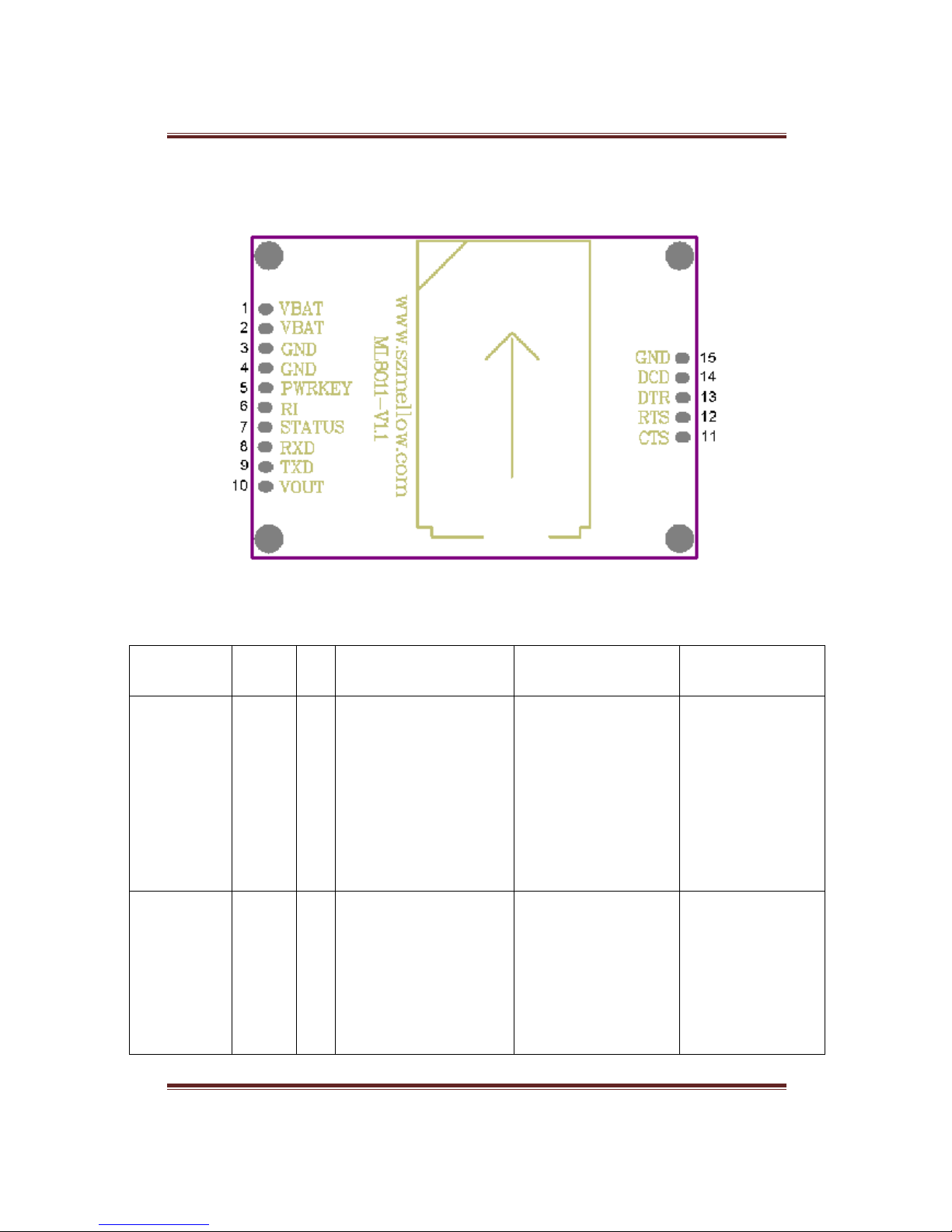
3.1PinDescription............................................................................................................................. 5
3.2Operatingmodes......................................................................................................................... 6
3.3Powersupply(VBAT)................................................................................................................ 7
3.4Powerupandpowerdownscenarios......................................................................................... 8
3.4.1PowerOn.............................................................................................................................. 8
3.4.2PowerdownmoduleusingthePWRKEY pin................................................................... 9
3.4.3PowerdownmoduleusingAT command.......................................................................... 9
3.4.4Over-voltageorunder-voltageautomaticshutdown.......................................... 10
3.4.5Restartmoduleusing thePWRKEY pin..........................................................................10
3.5Powersaving.............................................................................................................................11
3.5.1Minimumfunctionalitymode...........................................................................................11
3.5.2SLEEPmode(slowclockmode)......................................................................................12
3.5.3WakeupmodulefromSLEEPmode...............................................................................12
3.6Summaryofstatetransitions....................................................................................................12
3.7Serialinterfaces.........................................................................................................................13
3.8LEDindication...........................................................................................................................13
3.8.1GreenLedisthepower indication....................................................................................13
3.8.2RedLedistheWorkingstateindication..........................................................................13
4.Mechanicaldimension....................................................................................................................14
5.ProductList......................................................................................................................................15

L8011 GS GPRS odem User’s anual
Page 3
1.Introduction
ThisdocumentdefinestheML8011moduleseriesand describesthehardwareinterfaceofthe
ML8011modulethatconnectstothecustomer application.
Thisdocumentcanhelpcustomerquicklyunderstandmoduleinterface specifications,electrical
andmechanicaldetails. Withthehelpofthis document,associatedapplicationnotesanduser
guide,customercanuseML8011moduletodesign andsetupmobileapplicationsquickly.
2.Productconcept
TheML8011is aQuad-bandGSM/GPRSenginethatworksatfrequenciesGSM850MHz,
GSM900MHz,DCS1800MHzandPCS1900MHz.TheML8011featuresGPRS multi-slotclass
12andsupportstheGPRS coding schemesCS-1, CS-2,CS-3andCS-4.
TheML8011is integratedwithInternetserviceprotocols, whichareTCP/UDP, FTPandHTTP.
ExtendedATcommandshavebeendevelopedforcustomertousetheseInternetserviceprotocols
easily.
Table1Modulekeyfeatures
Feature
Implementation
Powersupply
Singlesupplyvoltage
3.6
V
–
4.6V,Normal4.0V
Frequencybands
●Quad
-
band: GSM850,GSM900,DCS1800, PCS1900.
●Themodulecansearchthesefrequencybandsautomatically
●ThefrequencybandscanbesetbyATcommand.
●ComplianttoGSM Phase2/2+
Transmittingpower
●Class4(2W)atGSM850andGSM900
●Class1(1W)atDCS1800 andPCS1900
GPRS connectivity
●GPRS multi
-
slotclass12 (default)
●GPRS multi-slotclass1~12(configurable)
●GPRS mobilestationclassB
Temperaturerange
●Normaloperation:
-
35°C~+80°C
●Restrictedoperation:-45°C~-35°Cand+80°C~+85°C 1)
●Storagetemperature:-45°C~+90°C
DATAGPRS:
●GPRS datadownlink transfer:max. 85.6kbps
●GPRS datauplinktransfer:max.85.6kbps
●Codingscheme:CS-1,CS-2,CS-3and CS-4
●SupporttheprotocolsPAP(PasswordAuthentication Protocol)

L8011 GS GPRS odem User’s anual
Page 4
CSD:
usually usedforPPP connections
●Internetserviceprotocols TCP/UDP/FTP/HTTP
●SupportPacketSwitchedBroadcastControl Channel(PBCCH)
●CSDtransmissionrates: 2.4,4.8,9.6, 14.4kbpsnon-transparent
●UnstructuredSupplementaryServicesData(USSD)support
SMS
●MT,MO,CB,Text andPDU mode
●SMS storage:SIMcard
FAX
Group3Class1and Class 2
SIMinterface
PortSIMcard:1.8V, 3V,Protectedagainst ESDwithaTVSdiode
array.
Serialinterface
●Supportfrom4800 bpsto115200 bps,defaultautobaudrate
●SupportTTL(3.3V)
●EmbedstandardATcommand GSM07.05and07.07)
Phonebookmanagement
Supportphonebooktypes:SM,FD, LD, RC,ON,MC
SIMApplicationToolkit
SupportSATcla
ss3, GSM11.14 Release99
Physicalcharacteristics
4
5
*3
2
.5
*12mm
1)Whenthemoduleworksin this temperaturerange, thedeviationsfromtheGSM specification
mightoccur. Forexample, thefrequencyerrororthephaseerrorcouldincrease.
Table2Codingschemesand maximumnetdataratesoverairinterface
Codingscheme
1Timeslot
2Timeslot
4Timeslot
CS
-
1:
9.05kbps
18.1kbps
36.2kbps
CS
-
2:
13.4kbps
26.8kbps
53.6kbps
CS
-
3:
15.6kbps
31.2kbps
62.4kbps
CS
-
4:
21.4kbps
42.8kbps
85.6kbps

L8011 GS GPRS odem User’s anual
Page 5
3.Applicationinterface
3.1PinDescription
Figure1Pin distribution
Table3Pin description
PIN NAME
PIN
I/O
DESCRIPTION
DC
CHARATERISTICS
COMMENT
VBAT
1,2
I
Modulemain power
supply. Thepower
supplyofmodulehasto
beasinglevoltagesource
ofVBAT=3.6V~4.6V,it
mustbeabletoprovide
sufficientcurrentina
transmittingburstwhich
typicallyrisesto2A
Vmax=4.6V
Vmin=3.6V
Vnormal=4.0V
Recommend toused
MIC29302/SP2930
2High-Current
Low-Dropout
Regulators
VOUT
10
O
Supply3.3Vvoltage
for
externalcircuit
Vmax=3.4V
Vmin=3.2V
Vnormal=3.3V
Imax=100mA
1.Ifunused, keep
thispin open.
2.Recommendto
addeda2.2~10uF
bypasscapacitor
whenusingthispin
topowersupply.

L8011 GS GPRS odem User’s anual
Page 6
GND
3,4,15
I
Power and digitalground
PWRKEY
5
I
Power
on/offcontrol
input,PWRKEY should
bepulledupfora
moment toturnon orturn
offthemodule.
TTL(3.3V)level,it
canbeconnectedtothe
MCU/ARM I/O port
indirectly.
STATUS
7
O
Usedtoindicatethe
moduleoperatingstatus.
Highlevelindicates
modulepower onandlow
levelindicatespower off.
TTL(3.3V)level,it
canbeconnectedtothe
MCU/ARM I/O port
indirectly.
Ifunused,keepthis
pin open.
RXD
8
I
TTL:
UARTReceivingdata.
TTL:
LogicL:0V±0.3V;
LogicH:3.3V±0.3V.
TXD
9
O
TTL:
UARTTransmittingdata.
RI
6
O
Ringindicator
TTL(3.3V)level,it
canbeconnectedtothe
MCU/ARM I/O port
indirectly.
Ifunused,keep
thesepin open.
CTS
11
O
Clear tosent
RTS
12
I
Request tosent
DTR
13
I
Dataterminalready
DCD
14
O
Data
carrierdetection
3.2Operatingmodes
Thetablebelow briefly summarizesthevariousoperatingmodesreferredtointhefollowing
chapters.
Table4Overviewofoperatingmodes
Mode
Function
Normal
operation
GSM/GPRS
SLEEP
Themodulewill automaticallygointoSLEEPmodeif
DTRissettohigh leveland thereisnointerrupt(such
asGPIOinterruptordataonserialport).
Inthis case,thecurrentconsumptionofmodulewill
reducetotheminimallevel.
DuringSLEEPmode,themodulecanstillreceive
pagingmessageandSMS fromthesystemnormally.

L8011 GS GPRS odem User’s anual
Page 7
GSMIDLE
Softwareisactive. Themo
dulehasregisteredtothe
GSMnetwork,andthemoduleisreadytosend and
receive.
GSMTALK
GSMconnectionisgoing.Inthismode,the
power
consumptionisdecidedbytheconfiguration ofPower
ControlLevel(PCL),dynamicDTXcontrol and the
workingRF band.
GPRSIDLE
ThemoduleisnotregisteredtoGPRS network. The
moduleis notreachablethrough GPRSchannel.
GPRS
STANDBY
The
moduleisregisteredtoGPRSnetwork,butno
GPRS PDPcontextis active. TheSGSNknowsthe
RoutingAreawherethemoduleis locatedat.
GPRS
READY
ThePDPcontext isactive,butnodatatransferis going
on.Themoduleis readytoreceiveorsendGPRS data.
TheSGSNknowsthecellwhere themoduleis located
at.
GPRSDATA
Thereis GPRSdatain transfer.Inthis mode, power
consumptionisdecidedbythePCL,workingRF band
and GPRS multi-slotconfiguration.
POWER
DOWN
Normalshutdownbysendingthe
“AT+QPOWD=1”command,using the
PWRKEY pin.Thepower managementASICdisconnectsthepower
supplyfromthebasebandpartofthemodule, andonlythepower supply
fortheRTCisremained.Softwareisnotactive. Theserialinterfacesare
notaccessible. Operatingvoltage(connectedtoVBAT)remainsapplied.
Minimum
functionality
mode(without
removing power
supply)
Usethe “AT+CFUN”commandcansetthemoduleto aminimum
functionalitymodewithoutremoving thepower supply.Inthiscase, the
RF partofthemodulewillnotworkortheSIMcardwillnotbe
accessible, orboth RFpartand SIMcardwillbeclosedall,buttheserial
portisstillaccessible. Thepower consumptionin this caseisverylow.
3.3Powersupply(VBAT)
ThepowersupplyofthemoduleisfromasinglevoltagesourceofVBAT=3.6V...4.6V. The
GSMtransmittingburstcancauseobviousvoltagedropatthesupplyvoltagethusthepower
supplymustbecarefullydesignedandis capableofprovidingsufficientcurrentupto2.0A.
Thecircuitdesignofthepowersupplyforthemodulelargely dependsonthepowersource.
Figure2showsareference design of+5V inputpowersource.Thedesignedoutputforthepower
supplyis4.0V,thusalinearregulatorcanbeused.Ifthere sabigvoltagedifferencebetweenthe
inputsourceandthedesiredoutput(VBAT), aswitchingconverter powersupplywouldbe

L8011 GS GPRS odem User’s anual
Page 8
preferableforitsbetterefficiencyespecially withthe2.0Apeakcurrentinburstmodeofthe
module.
Figure2recommend Powersupply
3.4Powerupand powerdownscenarios
3.4.1Power On
Customer sapplicationcanturnonthemodulebydrivingthepin PWRKEYtoahigh level
voltageand afterSTATUSpin outputsahighlevel, PWRKEY pin canbereleased.Customer
maymonitortheleveloftheSTATUSpin tojudgewhetherthemoduleispower-onornot.Ifthe
STATUSpinis ignored,pullthePWRKEY pintohigh levelformorethan2secondstoturnon
themodule. Thepoweron timingisillustratedasfollowingfigure 3.
Figure3Timing ofturnon themodule
①EnsuretheVBATvoltagestabilitybeforedrivingthepin PWRKEY to ahighlevelvoltage.
Recommendatleasttimeintervals of30 ms.
Note:Themoduleis settoautobaudratemode(AT+IPR=0)in default configuration.Intheauto
baudratemode,theURC “RDY”afterpoweringonisnotsenttohostcontroller.ATcommand

L8011 GS GPRS odem User’s anual
Page 9
canbesenttothemodule2-3seconds afterthemoduleis poweredon.Hostcontrollershould
firstly sendan “AT”or “at”string in orderthatthemodulecandetectbaud rateofhost controller,
andit shouldsend thesecondorthethird “AT”or “at”stringuntilreceiving “OK”stringfrom
module.Ifyouneedtousingfixedbaud rate, Thenan “AT+IPR=x;&W”shouldbesentto
moduleand savetheconfigurationtoflashmemoryofmodule.After theseconfigurations,the
URC “RDY”wouldbereceivedfromtheSerialPortofmoduleeverytimewhenthemoduleis
poweredon. Refer toChapter “AT+IPR”inARcommandmanual.
3.4.2Power downmoduleusingthePWRKEYpin
Customer sapplicationcanturnoffthemodulebydrivingthePWRKEYtoahighlevelvoltage
forcertain time.Thepower-downscenario isillustratedasin Figure 4.
Figure4Timingofturnoff themodule
Thepower-downprocedure causesthemoduletologofffromthenetworkandallows the
softwaretosaveimportantdatabeforecompletelydisconnecting thepower supply, thusitisa
safeway.Beforethecompletion ofthepower-downprocedurethemodulesendsouttheresult
codeshownbelow:
NORMALPOWERDOWN
Afterthis moment,nofurtherATcommandcanbeexecuted, andthenthemoduleentersthe
POWERDOWN mode, ThePOWERDOWN modecanalsobeindicatedbySTATUSpin,
whichisalowlevelvoltagein this mode.
3.4.3Power downmoduleusingAT command
Customer sapplicationcanuseanATcommand “AT+QPOWD=1”toturnoffthemodule. This
commandwillletthemoduletologofffromthenetworkandallowthesoftwaretosave
importantdatabefore completely disconnectingthepower supply,thusit is asafeway.

L8011 GS GPRS odem User’s anual
Page 10
Beforethecompletionofthepower-downprocedurethemodulesends outtheresultcodeshown
below:
NORMALPOWERDOWN
Afterthis moment,nofurtherATcommandcanbeexecuted, andthenthemoduleentersthe
POWERDOWN mode, ThePOWERDOWN modecanalsobeindicatedbySTATUSpin,
whichisalowlevelvoltagein this mode.
3.4.4Over-voltageorunder-voltageautomaticshutdown
Themodulewill constantlymonitorthevoltageappliedon theVBAT, ifthevoltage ≤3.5V, the
followingURC willbepresented:
UNDER_VOLTAGEWARNNING
Ifthevoltage ≥4.5V,thefollowingURCwillbepresented:
OVER_VOLTAGEWARNNING
Theuncriticalvoltagerangeis3.6Vto4.6V. Ifthevoltage>4.6V or<3.3V,themodulewould
automatically shutdown itself.
Ifthevoltage<3.3V,thefollowingURC will bepresented:
UNDER_VOLTAGEPOWERDOWN
Ifthevoltage>4.6V,thefollowingURC will bepresented:
OVER_VOLTAGEPOWERDOWN
Afterthis moment,nofurtherATcommandcanbeexecuted, themodulelogoff fromnetwork
andentersPOWERDOWN mode, ThePOWERDOWNmodecanalsobeindicatedbythepin
STATUS, whichisalowlevelvoltagein thismode.
3.4.5RestartmoduleusingthePWRKEYpin
Customer sapplicationcanrestartthemodulebydrivingthePWRKEYtoahighlevelvoltage
forcertain time,whichissimilar tothewaytoturnonmodule.Beforerestartingthemodule,at
least
500msshould bedelayedafterdetectingthelowlevelofSTATUS.Therestartscenariois
illustratedasthefollowingfigure5

L8011 GS GPRS odem User’s anual
Page 11
Figure5Timingofrestartsystem
3.5Powersaving
Upon systemrequirement, thereareseveralactionstodrivethemoduletoenterlowcurrent
consumptionstatus.Forexample, “AT+CFUN”canbeusedtosetmoduleinto minimum
functionalitymodeandDTRhardwareinterfacesignalcanbeusedtoleadsystem toSLEEP
mode.
3.5.1Minimumfunctionalitymode
Minimumfunctionalitymodereducesthefunctionalityofthemoduletominimumlevel,thus
minimizesthecurrentconsumptionwhentheslowclockingmodeisactivatedatthesametime.
Thismodeissetwiththe “AT+CFUN”commandwhichprovidesthechoice ofthefunctionality
levels <fun>=0,1,4.
●0:Minimumfunctionality;
●1:Fullfunctionality (default);
●4:DisablebothtransmittingandreceivingofRFpart;
Ifthemoduleis settominimumfunctionalityby “AT+CFUN=0”,theRF functionandSIMcard
functionwouldbeclosed.Inthis case,theserialportis still accessible, butallATcommands
correlativewithRFfunctionorSIMcardfunctionwill notbeaccessible.
Ifthemodulehasbeensetby “AT+CFUN=4”, theRFfunctionwillbeclosed,theserialportis
stillactive.Inthis case,allATcommands correlativewithRFfunctionwill notbeaccessible.
Afterthemoduleissetby “AT+CFUN=0”or “AT+CFUN=4”,it canreturntofullfunctionality
by “AT+CFUN=1”.
Fordetailedinformationabout “AT+CFUN”,pleaserefertoATcommandmanual.

L8011 GS GPRS odem User’s anual
Page 12
3.5.2SLEEPmode(slowclockmode)
TheSLEEPmodeis disabledindefaultsoftware configuration. Customer sapplication can
enablethismodeby “AT+QSCLK=1”. Ontheotherhand,thedefaultsettingis “AT+QSCLK=0”
andin thismode,themodulecan tenter SLEEPmode.
When “AT+QSCLK=1”issettothemodule,customer sapplicationcancontrolthemoduleto
enterorexitfromtheSLEEPmodethroughpinDTR.WhenDTRissettohighlevel,andthereis
noon-airorhardware interrupt suchasGPIOinterruptordataonserialport,themodulewill
enter
SLEEPmodeautomatically.Inthismode,themodulecanstillreceivevoice, SMSorGPRS
pagingfromnetworkbuttheserialportisnotaccessible.
3.5.3Wakeup modulefromSLEEPmode
Whenthemoduleis in theSLEEPmode,thefollowingmethodscanwakeup themodule.
●If theDTRPin ispulleddowntoalowlevel,it wouldwakeupthemodulefromtheSLEEP
mode.Theserialportwillbeactiveabout20msafterDTRchangedtolowlevel.
●Receiving avoiceordatacall fromnetworktowakeupmodule.
●Receiving anSMS fromnetworktowakeupmodule.
Note:DTRpinshould beheld lowlevelduringcommunicatingbetweenthemoduleand
Customer sapplication.
3.6Summaryof statetransitions
Table5Summaryofstatetransition
Currentmode
Nextmode
Power Down
NormalMode
SleepMode
PowerDown
UsePWRKEY
pin
Normalmode
AT+QPOWD or
usePWRKEY pin,
SetAT+QSCLK=1
and pulluptheDTR
pintohighlevel
SleepMode
UsePWRKEYpin
PulldownDTR
pintolowlevel,
Receivingavoice
ordatacall from
network,
Receivingan
SMSfrom
network

L8011 GS GPRS odem User’s anual
Page 13
3.7Serialinterfaces
Theconnection schematicbetweenML8011andMCU/ARM shownin figure6, Dottedline:
optionalconnection.
Figure6connectto MCU/ARM
3.8LEDindication
3.8.1GreenLedis thepowerindication.
3.8.2RedLedistheWorkingstateindication.
TheWorking stateofthisLED islistinthetable6.
Table6WorkingstateoftheREDLed
state
ModuleFunction
Off
Themoduleisnotrunning(Power Off)
64msOn/800msOff
Themoduleisnotsynchronizedwith
network
64msOn/2000msOff
Themoduleissynchronizedwithnetwork
64msOn/600msOff
GPRS datatransferisongoing.

L8011 GS GPRS odem User’s anual
Page 14
4.Mechanicaldimension

L8011 GS GPRS odem User’s anual
Page 15
5.ProductList
Name
Unit
Quantity
Describe
Picture
ML8011
Item
1
Module
Antenna
Item
1
StandardSupply
Table of contents
Other Eddy Wireless Modem manuals