DCS RF24TR2 Manual

2
NOTE
!CAUTION
Contents:
Safety information ...............................................................2
Unpacking your appliance ...................................................3
Warranty registration............................................................3
Installing your appliance ......................................................4
Cabinet clearances .........................................................4
Leveling the appliance ....................................................4
Electrical connection ......................................................5
Installing the anti-tip device .................................................6
Product dimensions RF24T.................................................8
Using your Electronic control...............................................9
Using your beer dispenser.................................................10
Tap equipment and assembly.........................................10
CO2 regulator.................................................................14
Drain kit...........................................................................15
Care and cleaning ............................................................15
Cleaning the drain sump................................................15
Keg coupler cleaning.....................................................16
Faucet cleaning ............................................................16
Front grille .....................................................................16
Cabinet...........................................................................16
Interior.............................................................................16
Long term storage / winterization .......................................17
Stainless steel maintenance ............................................19
Door alignment .................................................................20
Energy saving tips .............................................................20
Troubleshooting.................................................................21
Obtaining service .............................................................21
Warranty ............................................................................22
Important Safety Instructions
Warnings and safety instructions appearing in this guide
are not meant to cover all possible conditions and situa-
tions that may occur. Common sense, caution, and care
must be exercised when installing, maintaining, or operat-
ing this appliance.
Recognize Safety Symbols,
Words, and Labels.
!WARNING
WARNING - You can be killed or seriously injured
if you do not follow these instructions.
CAUTION-Hazards or unsafe practices which could re-
sult in personal injury or property / product damage.
NOTE-Important information to help assure a problem
free installation and operation.
CONTENTS
State of California Proposition 65 Warnings:
WARNING: This product contains one or more chemicals
known to the State of California to cause cancer.
WARNING: This product contains one or more chemicals
known to the State of California to cause birth defects or
other reproductive harm..

3
NOTE
!CAUTION
!CAUTION
!CAUTION
A Message To Our Customers
Thank you for selecting this DCS Outdoor Refrigerator.
Because of this appliances’ unique features we have devel-
oped this Use and Care and Installation Guide. It contains
valuable information on how to properly install, operate and
maintain your new appliance for years of safe and enjoy-
able operation.
For your convenience, product questions can be answered
by a DCS Customer Care Representative at
1-888-936-7872, or email: customer.care@sherpaykel.com
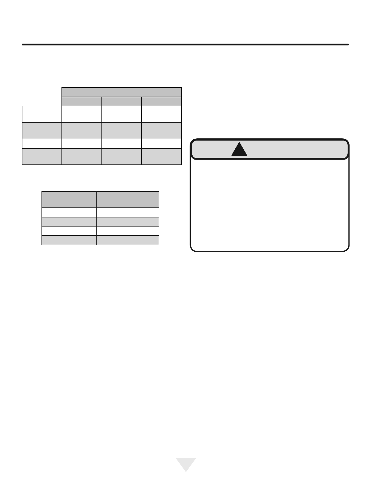
NOTE: Please write the Model, Code, and Serial Number
on this page for references (the serial plate is located on
the upper left side, inner wall).
MODEL NUMBER:
CODE:
SERIAL NUMBER:
NOTE: Inspect the product to verify that there is no ship-
ping damage. If any damage is detected, call the shipper
and initiate a damage claim. DCS by Fisher & Paykel is not
responsible for shipping damage.
DO NOT discard any packing material (box, pallet, straps)
until the unit has been inspected.
Help Prevent Tragedies
Child entrapment and suffocation are not problems of the
past. Junked or abandoned refrigerators are still dangerous
- even if they sit out for "just a few hours".
If you are getting rid of your old refrigerator, please follow
the instructions below to help prevent accidents.
Before you throw away your old refrigerator or freezer:
• Take off the doors or remove the drawers.
• Leave the shelves in place so children may not easily
climb inside.
Remove Interior Packaging
Your appliance has been packed for shipment with all parts
that could be damaged by movement securely fastened.
Remove internal packing materials and any tape holding in-
ternal components in place. The owners manual is shipped
inside the product in a plastic bag along with the warranty
registration card, and other accessory items.
Important
Keep your carton and packaging until your appliance has
been thoroughly inspected and found to be in good condi-
tion. If there is damage, the packaging will be needed as
proof of damage in transit. Afterwards please dispose of all
items responsibly.
Dispose of the plastic bags which can be a suffocation
hazard.
Note to Customer
This merchandise was carefully packed and thoroughly
inspected before leaving our plant. Responsibility for its
safe delivery was assumed by the retailer upon acceptance
of the shipment. Claims for loss or damage sustained in
transit must be made to the retailer.
DO NOT RETURN DAMAGED MERCHANDISE TO THE
MANUFACTURER - FILE THE CLAIM WITH THE
RETAILER.
If the appliance was shipped, handled, or stored in other
than an upright position for any period of time, allow the ap-
pliance to sit upright for a period of at least 24 hours before
plugging in. This will assure oil returns to the compressor.
Plugging the appliance in immediately may cause damage
to internal parts.
!WARNING
EXCESSIVE WEIGHT HAZARD
Use two or more people to move product.
Failure to do so can result in personal injury.
UNPACKING YOUR APPLIANCE

4
!CAUTION
Figure 1
Front Leveling
Legs
Front Grille,
keep this area
open.
Rear
Leveling
Legs
Select Location
The proper location will ensure peak performance of your
appliance. We recommend a location where the unit will
be out of direct sunlight and away from heat sources. To
ensure your product performs to specifications, the recom-
mended installation location temperature range is from 50
to 100°F (10to 38°C).
Cabinet Clearance
Ventilation is required from the bottom front of the appli-
ance. Keep this area open and clear of any obstructions.
Adjacent cabinets and counter top can be installed around
the appliance as long as the front grille remains unobstructed.
Front Grille
Do not obstruct the front grille. The openings within the
front grille allow air to ow through the condenser heat ex-
changer. Restrictions to this air ow will result in increased
energy usage and loss of cooling capacity. For this reason
it is important this area not be obstructed and the grille
openings kept clean (See Figure 1). The use of a custom
made grille is not recommended as it may restrict air ow.
INSTALLING YOUR APPLIANCE
Leveling Legs
Adjustable legs at the front and rear corners of the appli-
ance should be set so the unit is rmly positioned on the
oor and level from side to side and front to back. The
overall height of your appliance may be adjusted between
the minimum, 333⁄4" (85.7 cm), by turning the leveling leg in
(CW ↷) and the maximum, 343⁄4" (88.3 cm) by turning the
leveling leg out (CCW ↶).
To adjust the leveling legs, place the appliance on a solid
surface and protect the oor beneath the legs to avoid
scratching the oor. With the assistance of another person,
lean the appliance back to access the front leveling legs.
Raise or lower the legs to the required dimension by turning
the legs. Repeat this process for the rear by tilting the appli-
ance forward using caution. On a level surface check the
appliance for levelness and adjust accordingly.
The front grille screws may be loosened and the grille ad-
justed to the desired height. When adjustment is complete
tighten the two front grille screws. (See Figure 2).
Figure 2
Front grille screw
Front grille

5
NOTE
Figure 5
Ground Fault Circuit Interrupters (GFCI) are prone to nui-
sance tripping which will cause the appliance to shut down.
GFCI’s are generally not used on circuits with power equip-
ment that must run unattended for long periods of time, un-
less required to meet local building codes and ordinances.
Electrical Connection
A grounded 115 volt, 15 amp dedicated circuit is required.
This product is factory equipped with a power supply
cord that has a three-pronged, grounded plug. It must be
plugged into a mating grounding type receptacle in accor-
dance with the National Electrical Code and applicable lo-
cal codes and ordinances (see Figure 5). If the circuit does
not have a grounding type receptacle, it is the responsibility
and obligation of the customer to provide the proper power
supply. The third ground prong should not, under any cir-
cumstances, be cut or removed.
INSTALLING YOUR APPLIANCE
Figure 3
Figure 4
Do not remove
ground prong
Electrical Shock Hazard
• Do not use an extension cord with this appliance.
They can be hazardous and can degrade product
performance.
• This appliance should not, under any circumstanc-
es, be installed to an un-grounded electrical supply.
• Do not remove the grounding prong from the power
cord. (See Figure 3).
• Do not use an adapter. (See Figure 4).
• Do not splash or spray water from a hose on the
appliance. Doing so may cause an electrical shock,
which may result in severe injury or death.
!WARNING

6
!CAUTION
NOTE
INSTALLING THE ANTI TIP DEVICE
FOR FREESTANDING INSTALLATIONS
Figure 6
Bottom View of
Beer dispenser
Anti-Tip
Bracket Leveling Leg
Front of cabinet
211⁄2"
(54.6 cm)
Step by step instructions for locating the
position of the bracket:
1) Decide where you want to place the beer dispenser.
Slide it into place, being careful not to damage the oor,
leaving 1" (2.5 cm) of clearance from the rear wall to allow
room for the anti-tip bracket.
2) Raise the rear leveling legs approximately 1⁄4" (6 mm) to
allow engagement with the anti-tip bracket. Level the unit
by adjusting all the leveling legs as required. Turning the
leveling leg counterclockwise will raise the unit and clock-
wise will lower the unit.
3) Make sure the beer dispenser is in the desired location,
then mark on the oor the rear and side corner of the cabi-
net where the anti-tip bracket will be installed. If the instal-
lation does not allow marking the rear corner of the cabinet,
then make temporary lines on the oor marking the front
corner of the cabinet, excluding the door. Slide the beer
dispenser out of the way. From the temporary line extend
the sidewall line back 211⁄2" (54.6 cm) as shown in Figure 6.
4) Align the anti-tip bracket to the marks on the oor so
the side of the bracket lines up with the side of the cabinet
mark, and the "V" notches on the anti-tip bracket line up
with the end of the 211⁄2" (54.6 cm) line (Rear of cabinet
line).
5) Fasten the anti-tip bracket to the oor using the supplied
screw. (See Figure 7).
6) Slide the cabinet back into position, making sure the rear
cabinet leveling leg slides under the anti-tip bracket engag-
ing the slot.
Floor Mount Installation
The anti-tip bracket is to be located on the oor in the left or
right rear corner of the beer dispenser as shown in
Figure 6.
!WARNING
•ALL APPLIANCES CAN TIP
RESULTING IN INJURY.
• INSTALL THE ANTI-TIP
BRACKET PACKED WITH
THE APPLIANCE.
•FOLLOW THE INSTRUC-
TIONS BELOW
!WARNING
If your refrigerator is not located under a counter
top (free standing), you must use an anti-tip device
installed as per these instructions. If the refrigerator is
removed from its location for any reason, make sure
that the device is properly engaged with the anti-tip
bracket when you push the refrigerator back into the
original location. If the device is not properly engaged,
there is a risk of the refrigerator tipping over, with the
potential for property damage or personal injury.
If installing on a concrete oor, concrete fasteners are
required, (not included with the anti-tip kit).
Any nished ooring should be protected with appropriate
material to avoid damage when moving the unit.

7
NOTE
INSTALLING THE ANTI TIP DEVICE
FOR FREESTANDING INSTALLATIONS
"V" notches
in bracket
"V" notches
in bracket
When the oor mounted anti-tip bracket is used the mini-
mum adjusted height of the cabinet is increased by
3⁄8" (9 mm).
Figure 7
Front of cabinet line
Rear of cabinet line
Figure 7a
211⁄2"
(54.6 cm)
Rear Leveling leg
Screw
Side of cabinet line

8
"A"
"B"
"C"
"D"
"D"
"E"
"E"
"H"
"G"
"F"
"J"
If necessary to gain clearance inside the rough-in
opening a hole can be cut through the adjacent cabi-
net and the power cord routed through this hole to a
power outlet. Another way to increase the available
opening depth is to recess the power outlet into the
rear wall to gain the thickness of the power cord plug.
ROUGH-IN OPENING DIMENSIONS CABINET DIMENSIONS
MODEL "A" "B" "C" "D" "E" "F" "G" "H" "J"
RF24T
RF24BT
24" (61 cm)
24 ½" (62 cm)
(with optional
DCS side trim kit)
**34" to 35"
(86.4 to 88.9 cm) *237⁄8"
(60.7 cm)
333⁄4" to 343⁄4"
(85.7 to 88.3 cm)
2323⁄32"
(60.2 cm)
261⁄4"
(66.7 cm)
4613⁄32"
(117.9 cm)
261⁄4"
(66.7 cm)
PRODUCT DATA
MODEL
ELECTRICAL
REQUIREMENTS***
PRODUCT
WEIGHT
RF24T, RF24BT 115V/60Hz/15A 140 lbs
(63.6 kg)
Figure 9
211⁄2"
(54.6 cm)
121⁄4"
(31.1 cm)
1115⁄16"
(30.3 cm)
11"
(27.9 cm)
Figure 8
* Depth dimension of rough-in opening may vary depend-
ing on each individual installation. To recess entire door "F"
dimension plus 1" (2.5 cm) for thickness of power cord plug
is required.
** Minimum rough-in opening required is to be larger than
the adjusted height of the cabinet.
*** A grounded 15 amp dedicated circuit is required. Follow
all local building codes when installing electrical and appli-
ance.
PRODUCT DIMENSIONS
Figure 8a

9
USING YOUR ELECTRONIC CONTROL
Figure 10
Electronic control
Control Function Guide
Function Command Notes
ON/OFF Press and hold for 5 seconds. Unit will immediately turn ON or OFF.
Leave Interior Light On Press and release to leave interior light on for
3 hours; press again to deactivate.
After 12 hours, factory default is restored; light will turn on when
door is open.
Adjust Temperature Press or and release.
When the display is ashing, press or to adjust the set
point temperature. Note: temperature displayed is the actual
temperature inside unit.
Toggle Between oF / oC Hold and for 5 seconds. The display will change units.
Enable Sabbath Mode Press and hold for 5 seconds and release.
The oF / oC symbol will ash briey after 5 seconds. Interior
light and display will go dark and remain so until user resets
mode - unit continues to operate.
Disable Sabbath Mode Press , hold for 5 seconds and release. Display and interior light return to normal operation.
Showroom Mode Hold and for 5 seconds.
Display will show for 2 seconds. Interior light and display
will function normally, but the compressor and fans will not be
energized. Repeat command to return to normal operation.
Display will show for 2 seconds.
NOTE
Temperature displayed reects actual temperature inside unit. If the
temperature displayed is dierent than selected, the unit is progressing
towards the selected temperature. Time to reach set point varies based
upon ambient temperature, temperature of product loaded, door
openings, etc. DCS recommends allowing the unit to reach set points
before loading.

10
USING YOUR BEER DISPENSER
Tap Equipment and Assembly
Your dispensing kit includes the following parts:
Polished stainless steel tower with clear beer line (single
or double dispense)
Tower Gasket
Phillips oval head screws
Knob for Tower (Faucet Handle)
Keg coupler(s)
CO2regulator with red gas line(s) attached
Empty 5 pound CO2tank
Plastic clamp(s) large and small
Faucet wrench
Tools required for installation:
Flat bladed screwdriver
Phillips screwdriver
Pliers
Adjustable wrench or a 11⁄8" open end wrench
1⁄2" open end wrench
Barrel Sizes
1/6 barrel 1/4 Barrel 1/2 Barrel
Height 235⁄16"
(59.2 cm)
1413⁄16"
(37.6 cm)
235⁄16"
(59.2 cm)
Diameter 91⁄4"
(23.5 cm)
17"
(43.2 cm)
17" to 171⁄4"
(43.2 to 43 cm)
Gallons 5.16 7.75 15.5
#12 ounce
Glasses 60 82 163
This beer dispensing unit will support 1⁄2barrel or 1⁄4bar-
rel. The double draft tower units can support two sixth (1⁄6)
barrels of beer. See chart below for quantity of beer in each
barrel size.
Table A
Table B
Keg Size #of kegs per
5 pound CO2 Tank
5 gallon Corny 15 to 22
1/6 barrel 14 to 21
1/4 Barrel 10 to 14
1/2 Barrel 5 to 7
CO2 can be dangerous. If it becomes difcult to
breathe and/or your head starts to ache, a high
concentration of carbon dioxide may be present.
Leave the area immediately.
• The CO2 tank must always be connected to the
regulator. Never connect the tank to the keg.
• The CO2tank must be securely mounted in the
upright position. Secure it with the chain pro-
vided.
• Never drop or throw the CO2tank.
• Keep the CO2tank away from heat.
• Ventilate the area after a CO2leak.
!WARNING
1. Remove shelving and packaged components from the
interior of the refrigerator before beginning the assem-
bly process.
2. Take your empty 5 pound CO2tank to your local gas
supply dealer to be lled. You can usually nd them in
your "yellow pages" under "Welding Supply" or "Fire
Protection". One 5 pound tank can process many kegs
(see table "B") Your dealer should supply you with a
new plastic washer every time the tank is lled. This
washer is used at the regulator to tank connection. See
Figure 15 and 22 on page 11. Replace the old washer
with the new one whenever the tank is relled.
3. Tower mounting (if you are installing the unit under a
counter skip to step 4). If you are mounting the tower
directly to the top of the refrigerator, rst remove the
four screws from the top of the refrigerator. Feed the
clear beer line through the tower gasket and the large
hole in the refrigerator top. Align the 4 holes in the
tower with the 4 holes in the refrigerator top and secure
the tower with the 4 screws removed previously. Skip to
step 5.

11
B
B
B
B
5 Pound
CO2Tank
5 Pound
CO2Tank
Figure 14Figure 20
A
A
A
A
A
A
C
C
C
C
C
C
Regulator
with red
airline
Regulator
with red
airline
Keg
Coupler Keg
Coupler
Keg
Coupler
Single
Dispense
Tower
Double
Dispense
Tower
AC
Hose clamps
use for connections
and
AC
Hose clamps
use for connections
and
A A
Single Dispense Tower Kit
Connect to ,etc........ A A
Double Dispense Tower Kit
Connect to ,etc........
Figure 11
Figure 12
Figure 13
Figure 18
Figure 19
Figure 21
Figure 17
Figure 15
Figure 16
USING YOUR BEER DISPENSER

4. If you are installing your keg refrigerator under a
counter you will need to drill 5 holes in the counter top
to mount the tower. 1⁄2" diameter
hole located at the center of the tower for the beer
line, locate approximately 131⁄2" (34.3 cm) from the
front edge of the counter top (based on a counter top
depth of 255⁄16"). Next drill the 4 tower mounting holes
per the dimensions in Figure 22. The hole diameter is
depen-dent on the counter top material and if screw
anchors are required. The screws supplied are in the
literature pack and are a #10 x 1" type AB stainless
steel screw. Mark and cut the rectangular cut out for
the drain sump. After the holes are drilled and the keg
refrigerator is in place under the counter top feed the
beer line through the tower gasket, the 11⁄2" hole in the
counter top and the hole in the top of the keg
refrigerator. Mount the tower to the counter top with
the 4 screws provided.
5. Mount the regulator to the CO2tank (connection B).
Note that the regulator has left hand threads and has
to be turned counterclockwise to tighten. Tighten with
the adjustable wrench or the 11⁄8" open end wrench.
6. Connect the red air line(s) from the regulator to the
large large
hose clamp (connection C ).
7. Connect the clear beer line from the tower to the
small small
hose clamp (connection A ).
12
Diameter
to suit
Rear of counter top
27⁄8"
(7.3 cm)
13⁄8"
(3.5 cm)
typical 11⁄2(38 mm)
Diameter
counter
top depth
255⁄16"
(64.3 cm)
Figure 22
Figure 23
Figure 24
Tower
!CAUTION
USING YOUR BEER DISPENSER
4¼”
(10.8 CM)
6⅜”
(16.2 CM)
6⅛”
(15.6 CM)
12¼”
(31.1 CM)
¼” (6 MM)
radii,
typical
The cutout dimensions shown in Figure 22are based on a
255⁄16" (64.3 cm) deep counter top. Your counter top may
be different than this and require other front to back dimen-
sioning. Refer to the product dimensions on page 8 when
determining the required dimensions.
Grate from
top of beer
dispenser
Counter top
sump from
literature pack

13
Figure 26
Figure 26a
Rotate the top of the coupler coun-
ter clockwise to extend the coupler
to the to the "OFF"position.
Coupler
extended
8. Locate the CO2tank in the corner of the refrigerator as
shown in Figure 25and secure with the chain. Close
the faucet handle on the tower.
9. Hooking up the keg coupler to the keg: Verify the cou-
pler is in the "OFF" position (see Figure 26a).Align the
lugs on the keg with the corresponding openings on the
keg coupler and turn clockwise until the coupler stops
(about 90°). Push down and twist the top of the coupler
clockwise to allow gas to enter the keg.
Figure 25
Chain-The chain is fastened and taped
to the top of the interior liner. Remove
the tape and secure the CO2tank in
place in the back right corner.
Push faucet handle back toward
tower to close the faucet
USING YOUR BEER DISPENSER
Lugs
on keg
Figure 26b

14
CO2 Regulator (Double Dispense Tower)
Your beer dispenser comes equipped with a 5 pound CO2
tank and a dual gauge regulator. The lower gauge should
be reading approximately 750 psi (52 bar) when the tank is
properly lled and the tank is not in the refrigerator (at room
temperature). The tank will read less when chilled. Use this
lower gauge as an indicator of how much CO2you have left
in the tank.
The upper gauge reads the pressure being supplied to the
beer keg. Follow the procedure below to adjust the pres-
sure to 12 - 14 psi (0.8 to 1 bar) for lager beer or 9 - 12 psi
(0.6 to 0.8 bar) for ale's.
To adjust the pressure (Upper Gauge):
1. Close the shutoff valves at the bottom of the regulator.
2. Be sure the faucet handle is closed on the tower (see
Figure 28).
3. Loosen the lock nut by turning ↶counterclockwise us-
ing the 1⁄2" open end wrench until loose, this will allow
adjustment of the pressure adjustment screw.
4. With the flat bladed screwdriver turn the adjustment
screw ↷ clockwise to increase the pressure or ↶ coun-
terclockwise to decrease the pressure.
5. Open the shutoff valve on the bottom of the regula-tor.
The gauge reading may drop but will return very
quickly.
6. Pull the ring on the keg coupler to allow the gas to flow
momentarily.
7. Make any fine adjustments if necessary with the adjust-
ment screw.
8. Tighten the locknut with the 1⁄2" open end wrench by
turning clockwise ↷.
CO2 Regulator (Single Dispense Tower)
Your beer dispenser comes equipped with a 5 pound CO2
tank and a single gauge regulator. The gauge reads the
pressure being supplied to the beer keg. Follow the proce-
dure below to adjust the pressure to 12 - 14 psi (0.8 to 1
bar) for lager beer or 9 - 12 psi (0.6 to 0.8 bar) for ale's.
To adjust the pressure (Single Gauge):
1. Close the shutoff valve at the bottom of the regulator.
2. Be sure the faucet handle is closed on the tower (see
Figure 25).
3. Loosen the lock nut by turning ↶counterclockwise us-
ing the 1⁄2" open end wrench until loose, this will allow
adjustment of the pressure adjustment screw.
4. With the flat bladed screwdriver turn the adjustment
screw ↷ clockwise to increase the pressure or ↶ coun-
terclockwise to decrease the pressure.
5. Open the shutoff valve on the bottom of the regula-tor.
The gauge reading may drop but will return very
quickly.
6. Pull the ring on the keg coupler to allow the gas to flow
momentarily.
7. Make any fine adjustments if necessary with the adjust-
ment screw.
8. Tighten the locknut with the 1⁄2" open end wrench by
turning clockwise ↷.
Ring on keg
coupler
Figure 28(Regulator
for Single Dispense
Tower)
Figure 29 (Regulator for
Double Dispense Tower)
(2) shutoff
valves (closed
position shown)
Upper Gauge
Figure 27
Pressure Gauge
Lower Gauge
Pressure
Adjustment
Screw Lock Nut
USING YOUR BEER DISPENSER
Pressure
Adjustment
Screw
Lock Nut
shutoff valve
(closed posi-
tion shown)

15
Figure 30
Unscrew
cap
Removable
grate for clean-
ing sump area
Drain kit (All Models): The drain kit is shipped in
place and ready to use. To empty: Pull drain hose out of
bottle cap, remove bottle from unit, unscrew cap and dis-
card waste and rinse bottle. Reinstall bottle in unit.
Cleaning the drain sump:
On a free standing beer dispenser remove the grate from
in front of the tower, clean with soap and water and dry
before reinstalling. Clean the sump area with soapy water
On a built in beer dispenser remove the grate and coun-
ter top sump, clean with soap and water and dry before
reinstalling. Clean the sump area with soapy water and dry.
(See Figure 31).
Counter top
sump
Clean and dry
sump area
Figure 31
Push faucet handle back toward
tower to close the faucet
USING YOUR BEER DISPENSER AND CARE AND CLEANING

16
Faucet Cleaning
Turn off the gas supply with the shutoff valve(s) under the
regulator (see Figure 28or 29) and open the faucet to re-
lieve the pressure. To remove the faucet from the tower
use the spanner wrench provided. Place the pin on the
wrench into the hole on the faucet collar and turn clockwise
↷to remove the faucet. (See Figure 34).
Remove the knurled cap from the faucet body just below
the handle and pull the handle assembly from the faucet.
This will allow the shaft to be removed from the back of the
faucet, see Figure 35.
Soak all faucet parts in hot water or a solution of hot water
and a sanitizing solution. Do not use soap. Rinse thorough-
ly with clean water.
Reassemble faucet, assemble faucet to tower (be sure
faucet is in off position), and turn on gas valve.
Figure 34
Figure 35
After removing the
handle the shaft will
slide out the back of the
faucet
Unscrew knurled
cap on faucet body
and remove handle
assembly
Place pin on
wrench into hole
in faucet collar.
CARE AND CLEANING
Figure 33
Figure 32
Cleaning and Maintaining Dispensing System
The dispensing system needs to be cleaned between usage to
prevent spoilage and/or foul taste in your beer.
Cleaning
Remove the keg coupler from the keg if necessary. Close the gas
valve(s) below the regulator, remove both the red gas line(s) and
clear beer line(s) from the keg coupler(s) by remov-ing the plastic
hose clamps (See Figure 32). Soak and brush the keg coupler in
hot water or a sanitizing solution. Rinse thoroughly with clean
water. Dry all parts and reassemble.
!CAUTION
SHOCK HAZARD: Disconnect electrical power from the
appliance before cleaning with soap and water.
Cabinet
The stainless steel cabinet can be washed with either a
mild soap and water and thoroughly rinsed with clear water.
NEVER use abrasive scouring cleaners. Dry thoroughly
with a terry towel.
Interior
Wash interior compartment with mild soap and water. Do
NOT use an abrasive cleaner, solvent, polish cleaner or
undiluted detergent.
Care of Appliance
1. Avoid leaning on the door, you may bend the door
hinges or tip the appliance.
2. Exercise caution when sweeping, vacuuming or mop-
ping near the front of the appliance. Damage to the
grille can occur.
3. Periodically clean the interior of the appliance as needed.
In the Event of a Power Failure
If a power failure occurs, try to correct it as soon as pos-
sible. Minimize the number of door openings while the
power is off so as not to adversely affect the appliance's
temperature.
Front Grille
Be sure that nothing obstructs the required air ow openings
in front of the cabinet. At least once or twice a year, brush or
vacuum lint and dirt from the front grille area (see page 4).

17
CARE AND CLEANING
Long term storage / winterization:
1. Time to Winterize, when the daily low ambient tempera-
ture is at or below 38°F (3.3°C).
2. Turn unit off, (see page 9).
3. Remove all contents.
4. If necessary, move the unit so you can gain access to
the rear of the product.
5. Unplug the unit from the power outlet.
6. It is also recommended that the power to the outlet be
turned-off if the circuit is not required for other items
during the Winter season.
7. Shut-off CO2tank valve.
8. Drain beer line(s)
9. Disassemble faucet and clean, (see page 16).
10. Soak and clean Sankey Low-Boy tap, (see page 16).
11. When cleaning unit pay particular attention to any
cracks and crevices that may have accumulated dirt
and debris.
!CAUTION
Operating of the unit at ambient temperatures below the
recommended Winterization temperature will void your war-
ranty.
a. Remove keg coupler (sankey tap), (see
page 16).
b. Remove faucet on tower, (see page 16).
c. Beer lines will gravity drain.
d. Clean beer line tubing.
12. Remove the front toe-grille, (see Figures 36and 37),
and use a brush and vacuum to clean dirt and debris
from beneath the unit.
13. Thoroughly clean the toe-grille and re-install on the unit.
14. Remove the rear access cover, (see Figure 38), and
use a brush and vacuum to clean dirt and debris from
the machine compartment.
• If the plastic defrost drain pan located
under the compressor contains water,
use a sponge to remove as much
water as possible
15. Thoroughly clean the rear access cover and re-install
on the unit.
16. Wipe down all interior surfaces with anti-bacterial
cleaner to be followed with clean rinse water to remove
any residual chemicals which could cause staining. Do
not use any abrasive cleaners or scouring pads.
•Remove plastic loor protector and
stainless steel lower edge guard to
clean underneath.
Front grille screw
Front grille
Figure 36
Remove oor
protector and
edge guard
and clean
Floor protector
Edge
guard
Figure 37
Figure 37a
Grille
Spacer
Clean out
behind
grille

18
CARE AND CLEANING
Start-Up After Long-Term Storage:
1. Connect the unit to electrical power.
2. If stored outside, it is recommended that the unit again
be thoroughly inspected per the storage instructions
above to address any dirt or debris from the weather
and/or animals/insects.
3. T
4. Allow 24-hrs for the unit to stabilize before loading
contents.
17. Leave door open and allow to completely dry out be-
fore closing door.
18. Thoroughly clean the door gasket with anti-bacterial
cleaner to be followed with clean rinse water to remove
any residual chemicals.
19. Thoroughly clean the exterior with a cleaner approved
for stainless steel . Do not use any abrasive cleaners
or scouring pads.
20. Any mounting hardware / fasteners that are showing
signs of corrosion should be replaced.
21. Once the exterior has been thoroughly cleaned, you
may want to apply a coating of car wax to help protect
against spotting from moisture, dirt, and debris that
may accumulate on the surfaces during the Winteriza-
tion period.
After completion of the above, you may choose to store the
unit indoors, although this is not required.
Remove 11
screws from
around the
perimeter of the
access cover
with a 5⁄16" nut
driver.
Figure 38
Figure 39
Remove the power
cord from the grommet
in the access cover.
Soak up water
from plastic
drain pan if
necessary
Clean out
debris

19
STAINLESS STEEL MAINTENANCE
Background
Stainless steel does not stain, corrode, or rust as easily as
ordinary steel, but it is not stain or corrosion proof. Stain-
less steels can discolor or corrode if not maintained prop-
erly.
Stainless steels differ from ordinary carbon steels by the
amount of chromium present. It is this chromium that
provides an invisible protective lm on the surface called
chrome-oxide. This protective chrome-oxide lm on the
surface can be damaged or contaminated, which may
result in discoloration, staining, or corrosion of the base
metal.
Care & Cleaning
Routine cleaning of the stainless steel surfaces will serve to
greatly extend the life of your product by removing contami-
nants. This is especially important in coastal areas which
can expose the stainless to severe contaminants such as
halide salts, (sodium chloride).
It is strongly recommended to periodically inspect and thor-
oughly clean crevices, weld points, under gaskets, rivets,
bolt heads, and any locations where small amounts of liquid
could collect, become stagnant, and concentrate contami-
nates. Additionally, any mounting hardware that is showing
signs of corrosion should be replaced.
Frequency of cleaning will depend upon the installation
location, environmental, and usage conditions.
Choosing a Cleaning Product
The choice of a proper cleaning product is ultimately that
of the consumer, and there are many products from which
to choose. Depending upon the type of cleaning and the
degree of contamination, some products are better than
others.
Typically the most effective and efcient means for routine
cleaning of most stainless steel products is to give the sur-
faces a brisk rubbing with a soft cloth soaked in warm water
and a gentle detergent, or mild mixture of ammonia. Rub-
bing should, to the extent possible, follow the polish lines of
the steel, and always insure thorough rinsing after cleaning.
Although some products are called "stainless steel clean-
ers," some may contain abrasives which could scratch the
surface, (compromising the protective chrome-oxide lm),
and some many contain chlorine bleach which will dull,
tarnish or discolor the surface if not completely removed.
After the stainless surfaces have been thoroughly cleaned,
a good quality car wax may be applied to help maintain the
nish.
Note: Stainless steel products should never be installed, or
stored in close proximity to chlorine chemicals.
Whichever cleaning product you chose, it should be used
in strict accordance with the instructions of the cleaner
manufacturer.

20
Bottom
of door
DOOR ALIGNMENT AND ENERGY SAVING TIPS
Door alignment:
The door should be parallel to the sides and top of the ap-
pliance. If alignment is necessary the door may be adjusted
by loosening the 2 screws which secure the door adjust-
ment bracket on the bottom of the door (see Figure 40a)
and adjusting the door side to side. Use a 5⁄32” allen wrench
aligning the door, tighten the screws securely.
Door should be
parallel to top
and sides of the
appliance.
Figure 40
Loosen (don't remove)
these two screws.
Figure 40a
Door
adjustment
bracket
The following suggestions will minimize the
cost of operating your refrigeration appliance.
1. Do not install your appliance next to a hot appliance
(cooker, dishwasher, etc.), heating air duct, or other
heat sources.
2. Install product out of direct sunlight.
3. Ensure the front grille vents at front of appliance be-
neath door are not obstructed and kept clean to allow
ventilation for the refrigeration system to expel heat.
4. Plug your appliance into a dedicated power circuit. (Not
shared with other appliances).
5. When initially loading your new product, or whenever
large quantities of warm contents are placed within
refrigerated storage compartment, minimize door
openings for the next 12 hours to allow contents to pull
down to compartment set temperature.
6. Maintaining a relatively full storage compartment will
require less appliance run time than an empty compart-
ment.
7. Ensure door closing is not obstructed by contents
stored in your appliance.
8. Allow hot items to reach room temperature before plac-
ing in product.
9. Minimize door openings and duration of door openings.
10. Use the warmest temperature control set temperature
that meets your personal preference and provides the
proper storage for your stored contents.
11. When on vacation or away from home for extended pe-
riods, set the appliance to warmest acceptable tem-
perature for the stored contents.
12. Set the control to the “off” position if cleaning the
appliance requires the door to be open for an extended
period of time.
This manual suits for next models
3
Table of contents
Other DCS Beverage Dispenser manuals