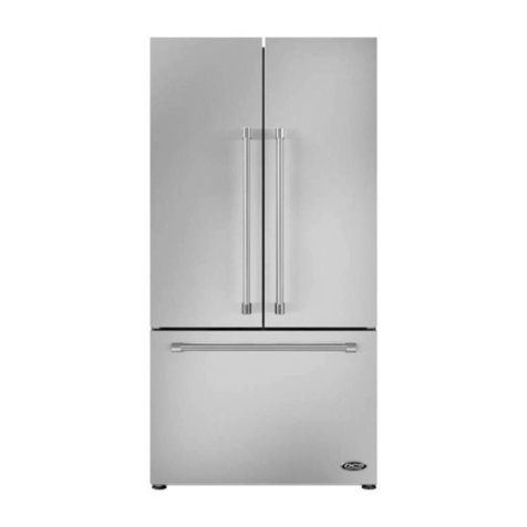
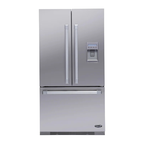
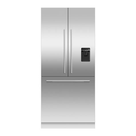
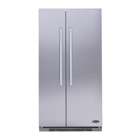
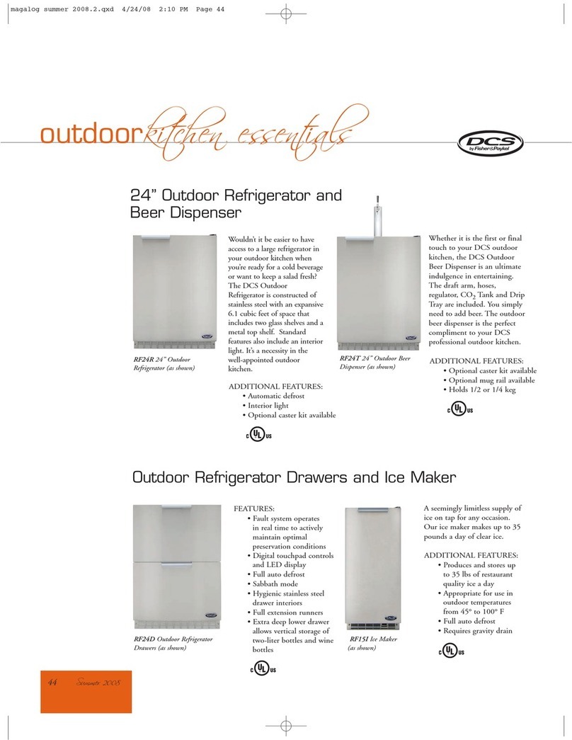
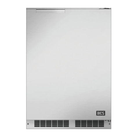
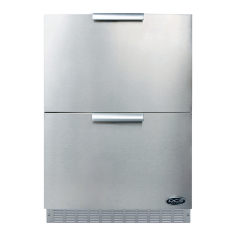
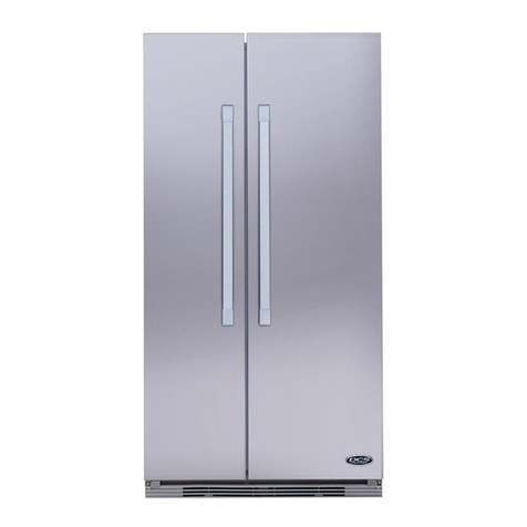
DCS ActiveSmart RS36A80JC User manual

ActiveSmart™ Built-in refrigerator
RS36A80JC DCS and
RS36A80UC DCS models
US CA
INSTALLATION INSTRUCTIONS
Frameless cabinetry
841337 B 08.15
www.dcsappliances.com


1
1 SAFETY AND WARNINGS
2 BEFORE INSTALLATION
3 COMPONENTS LIST
4 MAXIMUM DISTANCE OF HOSE AND POWER CORD
5 PRODUCT AND CAVITY DIMENSIONS
6 CAVITY PREPARATIONS
7 CUSTOM DOOR PANEL DIMENSIONS
OR
8 80” CAVITY
(2032 mm)
ATTACH ANTI-TIP BRACKET
8 84” CAVITY
(2134 mm)
ATTACH ANTI-TIP BRACKET
ATTACH TOP TRIM
9 ATTACH SIDE BASE BRACKETS AND INSTALLATION AIDERS
!0 CONNECT TO WATER AND ELECTRICAL SUPPLY
!1 PRE-ALIGNING YOUR PRODUCT
!2 TEMPORARILY FIXING YOUR PRODUCT AND ATTACHING DOOR STUDS
!3 INSTALL WATER FILTER CARTRIDGE AND KICKSTRIPS
!4 ASSEMBLE DOOR PANEL SET
!5 HANGING ICE & WATER DOOR PANEL
!6 HANGING NON-WATER DISPENSING DOOR PANELS
!7 ICE AND WATER INITIATION
!8 ATTACH FIXING BRACKETS
!9 ATTACH COVERS AND TOE KICK
@0 ATTACH BOTTOM KICKSTRIP
@1 ATTACH SIDE TRIM BRACKETS
@2 ATTACH SIDE TRIMS
@3 ADJUSTING HINGE TENSIONING SCREWS
@4 FINAL CHECKLIST
FOLLOW THE INSTALLATION SEQUENCE RELEVANT TO YOUR CABINETRY
RS36A80JC DCS and
RS36A80UC DCS models
FRAMELESS CABINETRY
(Frameless: Aligns the product with the cabinetry)
Note: shown with custom
panel attached to fridge
FRAMED CABINETRY
(Framed: Aligns the product with the frame of the cabinetry)
(refer to the flip side of the booklet)
Note: shown with custom
panel attached to fridge
NOTE: PRODUCT IS DESIGNED FOR FLUSH INSET INSTALLATION ONLY


3
1SAFETY AND WARNINGS
!WARNING!
Electric Shock Hazard
Read and follow the safety and warnings outlined in this installation
instructions guide before operating this appliance.
Failure to do so can result in death, electric shock, fire or injury
topersons.
!WARNING!
Cut Hazard
Take care – panel edges are sharp. Failure to use caution could result in
injury or cuts.
!WARNING!
This appliance is top-heavy and must be secured to prevent the
possibility of tippingforward.
To ensure that the appliance is stable under all loading conditions,
theanti-tip bracket and fittings supplied must be installed according
tothe following installation instructions by a professional installer.
Please follow the installation steps below to ensure your appliance is installed and
operatescorrectly.
Power
To ensure that the appliance is not accidentally switched off, connect your refrigerator to its
own isolating switch. Do not plug in any other appliance at this isolating switch.
For power requirements, please refer to the information on the serial plate. This is located
atthe front right-hand side of the drawer when open.
It is essential that the appliance is properly grounded (earthed).
Connect the appliance to the electrical supply (115VAC, 60 Hz) with the fitted plug and lead.
Follow the National Electrical Code and all local codes and ordinances when installing
thisproduct.
Warning: Ground Fault Circuit Interrupters (GFCI) may trip during normal operation of your
refrigerator and interrupt the power supply. The use of a GFCI is not recommended with
thisproduct.
Location
Your refrigerator should not be located in direct sunlight or next to any heat generating
appliance such as a cooktop, oven or dishwasher.
Your product is fitted with front and rear rollers designed for moving the product in
forwards and backwards direction.
Avoid moving the product in a sideways direction as this may damage the rollers or the floor
covering/surface.
Plumbing
Your product must be installed by a qualified appliance installer as incorrect plumbing can
lead to water leaks.
DCS by Fisher & Paykel Appliances does not accept responsibility for damage (including
water damage) caused by faulty installation or plumbing.
Door panel set
The standard appliance does not include a door panel set.
When designing custom door panels, these are only available for non-Water dispensing models.
To complete the integrated appliance for non-Water dispensing models the customer should
supply their own custom door panel set. All the hardware required to mount the door panel
sets to the refrigerator doors is supplied.
DCS by Fisher & Paykel door panel sets are available (Stainless steel door panels, model
numbers: RD3680C, RD3680CU, RD3684C and RD3684CU), and can be purchased through
your DCS by Fisher & Paykel dealer.
IMPORTANT!
SAVE THESE INSTRUCTIONS
The models shown in this installation guide may not be available in all markets and are subject to change at any time. For current details about model and specification availability in your country, please go to
our website www.dcsappliances.com or contact your local DCS by Fisher & Paykel dealer.
2BEFORE INSTALLATION
4
3COMPONENTS LIST
French door
hanging bracket
(2)
Drawer hanging bracket
(1)
Side bracket
(10)
Side strap
(10)
M5x10 pan head
Phillips screw
(10)
Door panel fittings – Included with standard appliance.
#8 x 16 mush washer screw
(46)
M8 stud
(6)
Side cover
(10)
Top cover
(4)
M8 nut
(6)
M8 washer
(6)
Anti-tip bracket fittings – Included with standard appliance.
Anti-tip bracket
(1)
Masonry plug
(4)
#10x40 pan head
Phillips screw
(4)

5
3COMPONENTS LIST
Optional accessories – The standard appliance does not include a door panel set.
DCS by Fisher & Paykel door panel sets are available (Stainless steel door panels). To complete the integrated appliance for non-Water dispensing models the customer should supply their own
custom door panel set.
M5x25 pan head
socket screw
(12)
Non-Water dispensing French panel (1)
Ice & Water French panel (1)
Drawer panel (1)
Model number: RD3680CU and RD3684CU
Non-Water dispensing French panels (2)
Drawer panel (1)
Model number: RD3680C and RD3684C
Water filter cartridge (1)
Part number: 81099
Filter cartridge tool
(1)
Collet locking key
(1)
Water fittings – Included with the standard appliance
¼” (6 mm) Adaptor
(1)
¼” comp. Stainless Steel
braided hose
(1)
M5x14 Mush Phillips SS
(34)
External display module (1)
(included with RS36A80UCDCS
standard appliance)
Drawer handle (1)
Door handle (2)

6
3COMPONENTS LIST
Top kickstrip grille
(1)
Kickstrip filter
(1)
Air divider
(1)
Product hardware – Included with standard appliance.
Screw cover
(4)
Bottom kickstrip grille
(1)
Side trim
(2)
Top trim joining bracket*
(2)
M5 nut
(4)
M5 x 8 countersunk
Phillips screw
(12)
Top trim*
(1)
Side trim bracket
(6)
Fixing bracket
(4)
Side base bracket
(2)
#8 x 19 twin thread screw
(8)
#8 x ⅝” (16 mm)
panhead screw
(3)
Installation aiders (4)
(required for Frameless
cabinetry installation)
M5 x 8 pan head
Phillips screw
(4)
*To be used when finished enclosure is 84” (2134 mm).
Hinge limiting pin
(1)

7
4MAXIMUM DISTANCE OF HOSE AND POWER CORD
Power cord (excl. plug) – 80 ¾” (2051mm)
RIGHT HAND SIDE
Power cord (excl. plug) – 80 ¾” (2051mm)
LEFT HAND SIDE
Power cord (excl. plug) – 31 ½” (800mm)
Water inlet hose – 53” (1350 mm) Water inlet hose – 84 ¼” (2120mm)

8
5PRODUCT AND CAVITY DIMENSIONS
PRODUCT DIMENSIONS inches (mm)
DOverall height of product* 79⁄” (2028)
EOverall width of product 35⅓” (890)
FMinimum cabinetry gap clearance from edge of custom panels** ⁄” (4)
GOverall depth of product (excluding front door panels) 23¾” (603)
HDepth of toe kick (measured from front of door panels***)4¾” (120)
IHeight of toe kick* 4 – 6” (102 – 152)
JDepth of product front panels (excludes handles)*** ¾” (19)
* Includes mounted feet.
** Refer to custom door panel dimensions section.
***Door panels and toe kick to be manufactured and fitted by cabinetmaker, maximum thickness ¾” (19mm).
CAVITY DIMENSIONS inches (mm)
AOverall height of cavity 80/84” (2032/2134)
BOverall width of cavity 36” (914)
COverall depth of cavity 24¾” (629)
Total front panel width with required gaps at sides = 36” (914mm). (Refer custom door panel dimensions section –
panel width + 2 x Fcabinetry gaps).
RS36A80JC DCS model shown only.
When designing custom door panels, these are only available for non-Water dispensing models.
E
B
H
C
A
A
I
J G
C
B
F
F
D
F
PROFILE VIEWFRONT VIEW
E
B
H
C
A
A
I
J G
C
B
F
F
D
F
PLAN VIEW
Flush with front
of cabinetry
E
B
H
C
A
A
I
J G
C
B
F
F
D
F
Frameless: Finished return
top and sides
Note: shown with custom
panel attached to fridge
E
B
H
C
A
A
I
J G
C
B
F
F
D
F
⁄” (4 mm)
3½”
(89 mm)

9
5PRODUCT AND CAVITY DIMENSIONS
DOOR CLEARANCE DIMENSIONS inches (mm)
ADepth of door (widest opening) measured from front of cabinetry 18⁄” (480)
BDepth of drawer (open) measured from front of cabinetry* 14⁄” (360)
CMinimum door clearance** to adjacent wall (115° – full internal access)* 12⁄” (315)
DMinimum door clearance** to adjacent wall (90° – reduced internal access)* 4⅓” (110)
* Does not include the custom door panels or handles to be manufactured and fitted by cabinetmaker.
** Measured from front cabinetry edge.
C
A
BBA
D
Wall Wall
90° DOOR OPENING115° DOOR OPENING
(FULL ROTATION)
For 90° door swing a hinge limiting pin is supplied with
your appliance. This pin fits in the boreholes of the top
hinge (refer to Z).
WARNING!
Before opening doors to the product, ensure the product
is on its base packer and the polystyrene stability blocks
are still in place. Failure to follow these instructions
could lead to serious injury or death.
1Open door to 90°.
2Using a hammer, drive the hinge limiting pin through the
boreholes which are now vertically aligned.
Z

10
5PRODUCT AND CAVITY DIMENSIONS – WITH RD3680C DOOR PANEL SET
RS36A80JC DCS model shown with RD3680C door panels.
CAVITY DIMENSIONS inches (mm)
AOverall height of cavity 80” (2032)
BOverall width of cavity 36” (914)
COverall depth of cavity 24¾” (629)
Total front panel width with required gaps at sides = 36” (914mm) (Eproduct width + 2 x Fcabinetry gaps).
Height of front panels with required gap above = 80” (2032mm) (Dproduct height + Fcabinetry gap).
PRODUCT DIMENSIONS inches (mm)
DOverall height of product* 79⁄” (2028)
EOverall width of product 35⅓” (906)
FMinimum cabinetry gap clearance from edge of product ⁄” (4)
GOverall depth of product (excluding front door panels) 23¾” (603)
HDepth of toe kick (measured from front of door panels) 4¾” (120)
IHeight of toe kick** 4” (102)
JHeight of bottom drawer panel 30⁄” (772)
KHeight of top door panels 45⁄” (1150)
LDepth of product front panels (excludes handles)*** ¾” (19)
* Includes mounted feet.
** Does not include custom toe kick to be manufactured and fitted by cabinetmaker.
***Optional Stainless steel front panels – Model no. RD3680C (non-Water dispensing model) and model no. RD3680UC
(Ice & Water model).
E
B
H
C
A
DA
J
I
L G
C
B
F
F
F
K
FRONT VIEW PROFILE VIEW
Flush with front
of cabinetry
E
B
H
C
A
DA
J
I
L G
C
B
F
F
F
K
PLAN VIEW
E
B
H
C
A
DA
J
I
L G
C
B
F
F
F
K
Frameless: Finished return
top and sides
E
B
H
C
A
DA
J
I
L G
C
B
F
F
F
K
3½”
(89 mm)
⁄” (4 mm)

11
5PRODUCT AND CAVITY DIMENSIONS – WITH RD3684C DOOR PANEL SET
RS36A80JC DCS model shown with RD3684C door panels.
CAVITY DIMENSIONS inches (mm)
AOverall height of cavity 84” (2134)
BOverall width of cavity 36” (914)
COverall depth of cavity 24¾” (629)
Total front panel width with required gaps at sides = 36” (914mm) (Eproduct width + 2 x Fcabinetry gaps).
Height of front panels with required gap above = 84” (2134mm) (Dproduct height + Fcabinetry gap).
PRODUCT DIMENSIONS inches (mm)
DOverall height of product* 83⁄” (2130)
EOverall width of product 35⅓” (906)
FMinimum cabinetry gap clearance from edge of product ⁄” (4)
GOverall depth of product (excluding front door panels) 23¾” (603)
HDepth of toe kick (measured from front of door panels)** 4¾” (120)
IHeight of toe kick* 4” (102)
JHeight of bottom drawer panel 30⁄” (772)
KHeight of top door panels 49⁄” (1252)
LDepth of product front panels (excludes handles)*** ¾” (19)
* Includes mounted feet.
** Does not include custom toe kick to be manufactured and fitted by cabinetmaker.
***Optional Stainless steel front panels – Model no. RD3684C (non-Water dispensing model) and model no. RD3684UC
(Ice & Water model).
E
B
H
C
A
DA
J
I
L G
C
B
F
F
F
K
Flush with front
of cabinetry
E
B
H
C
ADA
J
I
L G
C
B
F
F
F
K
PLAN VIEW
E
B
H
C
A
DA
J
I
L G
C
B
F
F
F
K
PROFILE VIEWFRONT VIEW
Frameless: Finished return
top and sides
E
B
H
C
ADA
J
I
L G
C
B
F
F
F
K
3½”
(89 mm)
⁄” (4 mm)

12
5PRODUCT AND CAVITY DIMENSIONS – WITH RD3680C/RD3684C DOOR PANEL SET
12
DOOR CLEARANCE DIMENSIONS inches (mm)
ADepth of door (widest opening) measured from front of door 18⁄” (480)
BDepth of drawer (open) measured from front of drawer, including handle 16⁄” (420)
CDepth of drawer (open) measured from front of drawer, excluding handle 14⁄” (360)
DMinimum door clearance* to adjacent wall (115° – full internal access) 13⁄” (335)
EMinimum door clearance* to adjacent wall (90° – reduced internal access) 5⅛” (130)
* Measured from front cabinetry edge.
D
A
BCBCA
E
Wall Wall
90° DOOR OPENING115° DOOR OPENING
(FULL ROTATION)
For 90° door swing a hinge limiting pin is supplied with
your appliance. This pin fits in the boreholes of the top
hinge (refer to Z).
WARNING!
Before opening doors to the product, ensure the product
is on its base packer and the polystyrene stability blocks
are still in place. Failure to follow these instructions
could lead to serious injury or death.
1Open door to 90°.
2Using a hammer, drive the hinge limiting pin through the
boreholes which are now vertically aligned.
Z

13
A
C
B
6CAVITY PREPARATIONS
MINIMUM CAVITY DIMENSIONS inches (mm)
AOverall height of cavity 80/84” (2032/2134)
BOverall width of cavity 36” (914)
COverall depth of cavity 24¾” (629)
ELECTRICAL SPECIFICATIONS
Supply 115VAC, 60Hz
Service 10 amp circuit
PLUMBING SPECIFICATIONS
Supply ¼” comp. Stainless steel braided hose
Pressure Minimum 22 psi (150 kPa)
Maximum 120psi (827kPa) @ 68°F (20°C)
Note: electrical connection can be located in an adjacent cabinet to either side of the fridge or above the fridge cavity.
Alternative area above cavity
for electrical connections
Electrical
Plumbing
Electrical
Plumbing
A
C
B
Floor
2⅞” (73 mm)
29¾” (756 mm)
5⅝” (143 mm)
Left side of cavity
Electrical and water connections must be within
this space if located behind the refrigerator
REAR OF CAVITY
2” (51mm)
Frameless: Finished return
top and sides
E
B
H
C
ADA
J
I
L G
C
B
F
F
F
K
3½”
(89 mm)
⁄” (4 mm)
IMPORTANT!
For ease of installation, ensure cavity width is consistent top to bottom and height is
consistent left to right.

14
7CUSTOM DOOR PANEL DIMENSIONS
H
D
A
B
D
g
A
E
I
F
C
g
RS36A80JC DCS
PANEL DIMENSIONS inches (mm)
AHeight of top door panel min.45⁄–max.49⁄” (min. 1150–max. 1252)
BWidth of top door panel 17¾” (451)
CGap between top door panels ⁄” (4)
DHeight of bottom drawer panel* 28⁄ – 30⁄” (722 – 772)
EHeight from bottom of product to top of bottom drawerpanel 34⁄” (874)
FWidth of bottom drawer panel 35⅓” (906)
GGap between top door panels and bottom drawer panel ⁄” (4)
HHeight of toe kick panel* 4 – 6” (101 – 152)
IMaximum depth of custom panels ¾” (19)
Maximum weight of an individual top door panel** 22 pounds (10kg)
Maximum weight of bottom drawer panel** 24¼ pounds (11kg)
Custom door panels to be manufactured and fitted by cabinetmaker.
Toe kick can be manufactured by cabinetmaker or stainless toe kick can be used.
Door handles available as a separate accessory.
*The bottom grille can be reduced to allow for a higher toe kick. Adjust the height of the bottom drawer panel accordingly.
** Includes weight of handle.
RS36A80JC DCS model shown only.
When designing custom door panels, these are only available for non-Water
dispensing models.
ISO VIEW
Note: top trim supplied for
84” (2134 mm) installation
H
D
A
B
D
g
A
E
I
F
C
g
PROFILE VIEW

15
7CUSTOM DOOR PANEL DIMENSIONS
The drawings below apply to non-Water dispensing models only (RS36A80JC DCS). Dimensions are shown in Imperial (inches) and apply for the preparation and installation of custom door panels.
For Dwg and Dxf files of the below panel preparation download the folder on http://www.dcsappliances.com/designers-architects/
All measurements to be made
from inner bottom corner.
For the second panel mirror
and repeat dimensions using
inner bottom corner as the
reference point.
Ensure handle is mounted
2⁄” from inner edge of panel
to the center – this will avoid
interference with brackets.
1⅜
16⁄
2⁄
4⅓ 6⁄
24⁄
26⁄
38⅝ 40
Ø⁄ REF
12x Pilot holes recommended for bracket attachment.
(Do not penetrate front surface).
15⁄
TOP PANEL – REAR VIEW
Ø⁄ REF
10x Pilot holes recommended for
bracket attachment.
(Do not penetrate front surface).
15⁄
5⅓
1⁄3⁄
19⅜
21⅓
16⅜
All measurements to be made
from top and centerline.
BOTTOM PANEL – REAR VIEW
Ensure handle screw heads are counter sunk into back
of panel to avoid interfering with hanging bracket.

16
880” (2032 mm) CAVITY – ATTACH ANTI-TIP BRACKET
IMPORTANT!
Safety requires refrigerators be stable when doors and/or drawer, are open. The anti-tip bracket and fittings supplied must be fitted to the wall of the finished enclosure to withstand
a220.5pound (100 kg) load. This will prevent the possibility of the appliance tipping forward, when doors and/or drawer, are open.
WARNING!
Failure to follow instructions can lead to serious injury or death.
When fastening with masonry plugs and/or screws:
Ensure the screws avoid electrical, gas and water conduits.
Ensure the surface the bracket is fastened to withstands a 220.5 pound (100 kg) load.
Ensure light-weight masonry material such as cinder block and new concrete (no curing time) are not used in installation.
Do not use metallic materials that may corrode, stain and/or damage the enclosure.
A
2⅜” min.
(60mm)
overlap
Bracket
PROFILE VIEW
Subtract 2⁄” (62mm) from above
finished enclosure
C
2⅜” min.
(60mm)
overlap
Bracket
PROFILE VIEW
Subtract 2⁄” (62mm) from above
finished enclosure
Spacer
B
2⅜” min.
(60mm)
overlap
Bracket
PROFILE VIEW
Subtract 2⁄” (62mm) from above
finished enclosure
For 80” (2032mm) cavity installation
Wooden/plaster board wall installation
1Project the end of the above finished enclosure to the center of the back wall and
subtract 2⁄” (62mm). This will locate the contact surface between the bracket and
the appliance (refer toA).
Ensure a structural beam/wall stud closest to the center of the wall enclosure is located.
2Fix bracket to the wall with screws x4 (#10 x 40 pan head Phillips screws).
Ensure screws hold tight and the bracket overlaps the appliance when it is positioned
(2⅜” min. (60mm)) for a secure hold.
Spacer installation
If a minimum 2⅜” (60mm) overlap cannot be achieved we recommend fastening
a solid spacer (wooden beam etc) behind the bracket.
1Ensure the length of the spacer corresponds to the enclosure’s width. Always
secure the spacer to existing studs on the enclosure wall (refer toC).
2Fix bracket to the spacer with screws x4 (#10 x 40 pan head Phillips screws).
Ensure screws hold tight and the bracket overlaps the appliance when it is
positioned (2⅜” min. (60mm)) for a secure hold.
Solid wall installation
1Project the end of the above finished enclosure to the center of the back wall and
subtract 2⁄” (62mm). This will locate the contact surface between the bracket
and the appliance (refer toB).
2Mark screw locations to drill Ø ¼” x 1 ⅜” (Ø 6.0mmx35mm) deep holes. Hammer
masonry plugs into the wall until flush x4. Fix bracket to the wall with screws x4
(#10 x 40pan head Phillips screws). Ensure screws hold tight.

17
884” (2134 mm) CAVITY – ATTACH ANTI-TIP BRACKET
IMPORTANT!
Safety requires refrigerators be stable when doors and/or drawer, are open. The anti-tip bracket and fittings supplied must be fitted to the wall of the finished enclosure to withstand
a220.5pound (100 kg) load. This will prevent the possibility of the appliance tipping forward, when doors and/or drawer, are open.
WARNING!
Failure to follow instructions can lead to serious injury or death.
When fastening with masonry plugs and/or screws:
Ensure the screws avoid electrical, gas and water conduits.
Ensure the surface the bracket is fastened to withstands a 220.5 pound (100 kg) load.
Ensure light-weight masonry material such as cinder block and new concrete (no curing time) are not used in installation.
Do not use metallic materials that may corrode, stain and/or damage the enclosure.
A
2⅜” min.
(60mm)
overlap
Bracket
PROFILE VIEW
Subtract 6⁄” (164mm) from above
finished enclosure
C
2⅜” min.
(60mm)
overlap
Bracket
PROFILE VIEW
Subtract 6⁄” (164mm) from above
finished enclosure
Spacer
B
2⅜” min.
(60mm)
overlap
Bracket
PROFILE VIEW
Subtract 6⁄” (164mm) from above
finished enclosure
Spacer installation
If a minimum 2 ⅜” (60mm) overlap cannot be achieved we recommend fastening
a solid spacer (wooden beam etc) behind the bracket.
1Ensure the length of the spacer corresponds to the enclosure’s width. Always
secure the spacer to existing studs on the enclosure wall (refer toC).
2Fix bracket to the spacer with screws x4 (#10 x 40 pan head Phillips screws).
Ensure screws hold tight and the bracket overlaps the appliance when it is
positioned (2 ⅜”min. (60mm)) for a secure hold.
Solid wall installation
1Project the end of the above finished enclosure to the center of the back wall and
subtract 6⁄” (164mm). This will locate the contact surface between the bracket
and the appliance (refer toB).
2Mark screw locations to drill ؼ” x 1⅜” (Ø 6.0mm x 35mm) deep holes. Hammer
masonry plugs into the wall until flush x4. Fix bracket to the wall with screws x4
(#10 x 40 pan head Phillips screws). Ensure screws hold tight.
For 84” (2134mm) cavity installation
Wooden/plaster board wall installation
1Project the end of the above finished enclosure to the center of the back wall and
subtract 6⁄” (164mm). This will locate the contact surface between the bracket and
the appliance (refer toA).
Ensure a structural beam/wall stud closest to the center of the wall enclosure is located.
2Fix bracket to the wall with screws x4 (#10 x 40 pan head Phillips screws).
Ensure screws hold tight and the bracket overlaps the appliance when it is positioned
(2⅜” min. (60mm)) for a secure hold.

18
884” (2134 mm) CAVITY – ATTACH TOP TRIM
IMPORTANT!
Take care when working with the appliance outside of the finished enclosure, as the
appliance is not secured and has the possibility of tipping forward.
2On the right side of the top trim, insert M5 nuts x2 onto the top and bottom slide.
Slide nuts towards the center of the trim, ~13” (330mm).
Repeat this process on the opposite side.
4At the top of the appliance, place the assembled top trim behind the existing appliance
trim. Bring the top trim forward and insert screw heads through the key holes of the joining
brackets (refer toA).
~13” (330mm) ~13” (330mm)
1Ensure all external packaging material is removed from the appliance before installation.
5Slide the screws located on the appliance sideways towards the narrow side of the key holes
on the joining bracket, and tighten screws to lock top trim in position (refer toB).
A
B
3Position joining brackets over the M5 nuts. Thread screws x2 (M5 x 8 pan head Phillips
screws) through bracket hole and secure.
Repeat this process on the opposite side.
This manual suits for next models
1
Table of contents
Other DCS Refrigerator manuals

DCS
DCS RF195A Mounting instructions

DCS
DCS ActiveSmart RF201A Wiring diagram

DCS
DCS RF24-D User manual

DCS
DCS RF24RE3 Manual

DCS
DCS RX215PJX1 Mounting instructions

DCS
DCS RF48SS User manual

DCS
DCS RX215UJX1 Parts list manual

DCS
DCS RF24R Training manual

DCS
DCS RX215 Series Mounting instructions

DCS
DCS RF195A Mounting instructions