DCS ActiveSmart RS36A72JC User manual

ActiveSmart™ Built-in refrigerator
RS36A72JC DCS and RS36A72UC DCS models
US CA
INSTALLATION INSTRUCTIONS
843160 A 06.15
www.dcsappliances.com


1
FOLLOW THE INSTALLATION SEQUENCE RELEVANT TO YOUR CABINETRY
RS36A72JC DCS and
RS36A72UC DCS models
Wooden/plaster
board wall installation
Solid wall
installation
Spacer
installation
Pex tube
installation
Copper tube
installation
!2 PRODUCT PREPARATION
!4 ATTACH SIDE TRIMS
!5 ASSEMBLE DOOR PANEL SET
!6 HANGING ICE & WATER DOOR PANEL
!7 HANGING NON-WATER DISPENSING DOOR PANELS
!8 TOP TRIM AND HINGE END CAPS
!9 INSTALL WATER FILTER CARTRIDGE
@1 FINAL CHECKLIST
@0 ATTACH COVERS AND KICKSTRIPS
!3 LEVEL YOUR PRODUCT
!1 CONNECT TO ELECTRICAL SUPPLY
3 COMPONENTS LIST
4 PRODUCT AND CAVITY DIMENSIONS
6 MAXIMUM DISTANCE OF POWER CORD
5 CAVITY PREPARATION
7 CUSTOM DOOR PANEL DIMENSIONS
8 ATTACH SIDE TRIM BRACKETS
9 ATTACH ANTI-TIP BRACKET
2 BEFORE INSTALLATION
1 SAFETY AND WARNINGS
!0 CONNECT TO WATER SUPPLY


3
1SAFETY AND WARNINGS 2BEFORE INSTALLATION
Please follow the installation steps below to ensure your appliance is installed and
operatescorrectly.
Power
To ensure that the appliance is not accidentally switched off, connect your refrigerator
toitsown isolating switch. Do not plug in any other appliance at this isolating switch.
For power requirements, please refer to the information on the serial plate. This is located
atthe front right-hand side of the drawer when open.
It is essential that the appliance is properly grounded (earthed).
Connect the appliance to the electrical supply (115VAC, 60 Hz) with the fitted plug and lead.
Follow the National Electrical Code and all local codes and ordinances when installing
thisproduct.
Warning: Ground Fault Circuit Interrupters (GFCI) may trip during normal operation of
your refrigerator and interrupt the power supply. The use of a GFCI is not recommended
withthisproduct.
Location
Your refrigerator should not be located in direct sunlight or next to any heat generating
appliance such as a cooktop, oven or dishwasher.
Your product is fitted with front and rear rollers designed for moving the product
inforwards and backwards direction.
Avoid moving the product in a sides ways direction as this may damage the rollers
orthefloor covering/surface.
Plumbing
Your product must be installed by a qualified plumber or a DCS by Fisher & Paykel
Authorized ServiceAgent as incorrect plumbing can lead to water leaks.
DCS by Fisher&Paykel Appliances does not accept responsibility for damage (including
water damage) caused by faulty installation or plumbing.
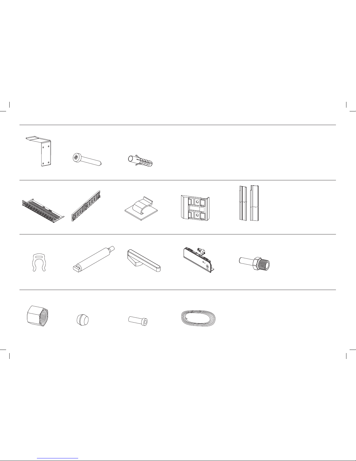
Door panel set
The standard appliance does not include a door panel set.
When designing custom door panels, these are only available for non-Water dispensing models.
To complete the integrated appliance for non-Water dispensing models the customer should
supply their own custom door panel set. All the hardware required to mount the door panel
sets to the refrigerator doors is supplied.
DCS by Fisher & Paykel door panel sets are available (Stainless steel door panels, model
numbers: RD3672C and RD3672CU), and can be purchased through your DCS by
Fisher&Paykel dealer).
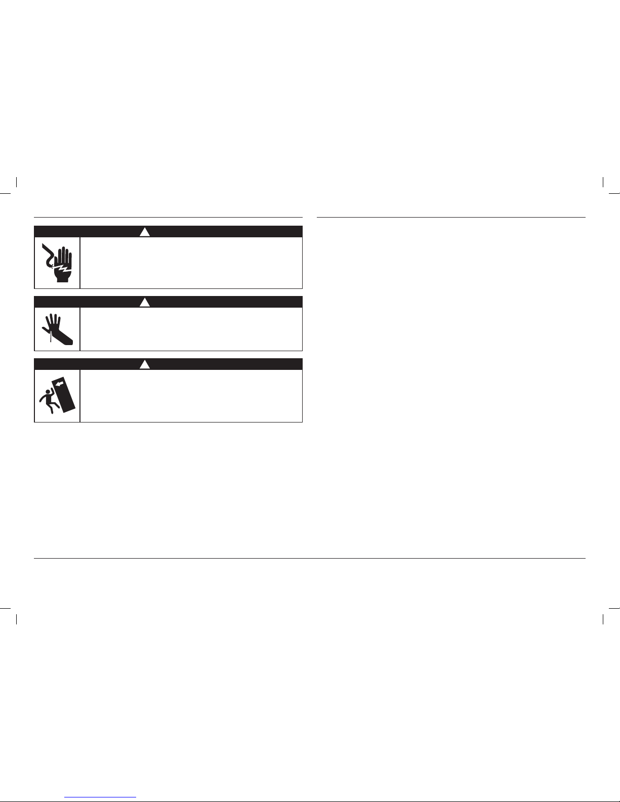
!WARNING!
Electric Shock Hazard
Read and follow the safety and warnings outlined in this installation
guide before operating this appliance.
Failure to do so can result in death, electric shock, fire or injury
topersons.
!WARNING!
Cut Hazard
Take care – panel edges are sharp. Failure to use caution could result in
injury or cuts.
!WARNING!
This appliance is top-heavy and must be secured to prevent the
possibility of tippingforward.
To ensure that the appliance is stable under all loading conditions, the
anti-tip bracket and fittings supplied must be installed according to the
following installation instructions by a professional installer.
IMPORTANT!
SAVE THESE INSTRUCTIONS
The models shown in this installation guide may not be available in all markets and are subject to change at any time. For current details about model and specification availability in your country, please go to
our website www.dcsappliances.com or contact your local DCS by Fisher & Paykel dealer.

4
3COMPONENTS LIST
French door
hanging bracket
(2)
Drawer hanging bracket
(1)
Side bracket
(10)
Side strap
(10)
M8 stud
(6)
Side cover
(10)
Top cover
(4)
M5 x 10 pan head
Phillips screw (10)
M8 nut
(6)
M8 washer
(6)
Door panel fittings – Included with standard appliance.
Optional accessories – The standard appliance does not include a door panel set.
DCS by Fisher & Paykel door panel sets are available (Stainless steel door panels). To complete the integrated appliance for non-Water dispensing models the customer should supply their own
custom door panel set.
M5 x 25 pan head
socket screw
(12)
Non-Water dispensing French panel (1)
Ice & Water French panel (1)
Drawer panel (1)
Model number: RD3672CU
Non-Water dispensing French panels (2)
Drawer panel (1)
Model number: RD3672C
#8 x 16 mush
washerscrew (34)
M5 x 14 Mush Phillips SS
(34)
Drawer handle (1)
Door handle (2)

5
3COMPONENTS LIST
Kickstrip grille
(1)
Kickstrip filter
(1)
Water filter cartridge (1)
Part number: 839041
Product hardware – Included with standard appliance.
Ice & Water fittings – Included with standard appliance.
External display module (1)
(included with RS36A72CU DCS
standard appliance)
Filter cartridge tool
(1)
Power cord clip
(1)
Anti-tip bracket fittings – Included with standard appliance.
Side trim bracket
(6)
Side trim
(2)
Collet locking key
(1)
¼”(6mm)
Compression nut
(1)
¼”(6mm)
Compression sleeve
(1)
¼” (6 mm) Tube insert
(1)
¼” (6mm) PEX tube
(1)
Water fittings – The standard appliance does not include water fittings. DCS by Fisher & Paykel water fittings are available (part number: 841301). These parts need to be purchased separately
by the customer and comply with local regulations.
#10x40 pan head
Phillips screw (4)
Anti-tip bracket (1) Masonry plug (4)
¼” (6 mm) Adaptor (1)
(required for copper water
tubing installation only)

6
PRODUCT DIMENSIONS inches (mm)
DOverall height of product* 71⁄” (1825)
EOverall width of product 35⅓” (890)
FMinimum cabinetry gap clearance from edge of custom panels** ⁄” (4)
GOverall depth of product (excluding front door panels) 23¾” (603)
HDepth of toe kick (measured from front of door panels***)2” (51)
IHeight of grille/toe kick* 4” (102)
JDepth of product front panels (excludes handles)*** ⅝” – ¾” (16–19)
* Includes mounted feet.
** Refer to custom door panel dimensions section.
***Door panels to be manufactured and fitted by cabinetmaker, min. ⅝” (16 mm) - max. ¾” (19 mm) thickness.
CAVITY DIMENSIONS inches (mm)
AOverall height of cavity 72” (1829)
BOverall width of cavity
(when adjoining cabinetry cannot share ⁄” (4mm) door gap)
36” (914)
COverall depth of cavity* 25” (635)
Total front panel width with required gaps at sides = 36” (914mm). (Refer to custom door panel dimensions section –
panel width + 2 x Fcabinetry gaps).
* Assumes a door panel thickness of ¾” (19mm).
E
B
H
C
A
A
I
J G
C
B
F
F
F
D
PROFILE VIEWFRONT VIEW
RS36A72JC DCS model shown only.
When designing custom door panels, with non-Water dispensing models.
4PRODUCT AND CAVITY DIMENSIONS
E
B
H
C
A
A
I
J G
C
B
F
F
F
D
E
B
H
C
A
A
I
J G
C
B
F
F
F
D
Flush with front
of cabinetry
PLAN VIEW
Framed: Finished return top and sides
Note: shows adjoining cabinetry
notsharing ⁄” (4 mm) door gap
⁄”
(4 mm)
E
B
H
C
A
A
I
J G
C
B
F
F
F
D
3½”
(89 mm)

7
DOOR CLEARANCE DIMENSIONS inches (mm)
ADepth of door (widest opening) measured from front of cabinetry 17⁄” (440)
BDepth of drawer (open) measured from front of cabinetry* 15¾” (400)
CMinimum door clearance** to adjacent wall* (115° – full internal access)* 11⁄” (300)
DMinimum door clearance** to adjacent wall* (90° – reduced internal access)* 3⁄” (100)
* Does not include the custom door panels or handles to be manufactured and fitted by cabinetmaker.
** Measured from front cabinetry edge.
90° DOOR OPENING115° DOOR OPENING
[FULL ROTATION]
A
B
C
BA
D
Wall Wall
90° DOOR OPENING115° DOOR OPENING
(FULL ROTATION)
4PRODUCT AND CAVITY DIMENSIONS

8
4PRODUCT AND CAVITY DIMENSIONS – WITH RD3672C DOOR PANEL SET
PRODUCT DIMENSIONS inches (mm)
DOverall height of product* 71⁄” (1825)
EOverall width of product 35⅓” (906)
FMinimum cabinetry gap clearance from edge of product ⁄” (4)
GOverall depth of product (excluding front door panels) 23¾” (603)
HDepth of toe kick (measured from front of door panels) 2” (51)
IHeight of grille/toe kick* 4” (102)
JHeight of bottom drawer panel 23⁄” (596)
KHeight of top door panels 44⁄” (1123)
LDepth of product front panels (excludes handles)** ¾” (19)
* Includes mounted feet.
** Optional Stainless steel front panels - Model no. RD3672C (non-Water dispensing model) and model no. RD3672CU
(Ice & Water model).
E
B
H
C
A
DA
J
I
L G
C
B
F
F
F
K
FRONT VIEW
RD3672JC model shown with RD3672C door panel set.
CAVITY DIMENSIONS inches (mm)
AOverall height of cavity 72” (1829)
BOverall width of cavity
(when adjoining cabinetry cannot share ⁄” (4mm) door gap)
36” (914)
COverall depth of cavity 25” (635)
Total front panel width with required gaps at sides = 36” (914mm) (Eproduct width + 2 x Fcabinetry gaps).
Height of front panels with required gap above = 72” (1829 mm) (Dproduct height + Fcabinetry gap).
E
B
H
C
A
DA
J
I
L G
C
B
F
F
F
K
PROFILE VIEW
E
B
H
C
A
DA
J
I
L G
C
B
F
F
F
K
Flush with front
of cabinetry
PLAN VIEW
Framed: Finished return top and sides
Note: shows adjoining cabinetry
notsharing ⁄” (4 mm) door gap
E
B
H
C
A
DA
J
I
L G
C
B
F
F
F
K
3½”
(89 mm)
⁄”
(4 mm)

9
4PRODUCT AND CAVITY DIMENSIONS – WITH RD3672C/RD3672CU DOOR PANEL SET
DOOR CLEARANCE DIMENSIONS inches (mm)
ADepth of door (widest opening) measured from front of door 17⁄” (440)
BDepth of drawer (open) measured from front of drawer, including handle 16⁄” (420)
CDepth of drawer (open) measured from front of drawer, excluding handle 14⁄” (360)
DMinimum door clearance to adjacent wall* (115° – full internal access) 12¾” (324)
EMinimum door clearance to adjacent wall* (90° – reduced internal access) 4¾” (121)
* Measured from front cabinetry edge.
90° DOOR OPENING115° DOOR OPENING
[FULL ROTATION]
AB C
D
BCA
E
Wall Wall
115° DOOR OPENING
(FULL ROTATION)
90° DOOR OPENING

10
!
A
C
B
A
C
B
!
5CAVITY PREPARATION
Electrical
Plumbing
Electrical
Plumbing
Recommended area above
cavity for connections
CAVITY DIMENSIONS inches (mm)
AOverall height of cavity 72” (1829)
BOverall width of cavity
(when adjoining cabinetry cannot share ⁄” (4mm) door gap)
36” (914)
COverall depth of cavity 25” (635)
Alternative electrical connection location
Floor
5⁄”
(150mm)
4⅓”
(110mm)
2⁄”
(75 mm)
5⁄”
(129mm)
5⁄”
(150mm)
31½” (800mm)
REAR VIEW OF CAVITY
RS36A72JC DCS RS36A72CU DCS
ELECTRICAL SPECIFICATIONS
Supply 115VAC, 60 Hz 115VAC, 60 Hz
Service 10 amp circuit 10 amp circuit
PLUMBING SPECIFICATIONS
Supply – ¼” (6mm) PEX hose or Copper tubing*
Pressure – Minimum 22 psi (150 kPa)
Maximum 120 psi (827 kPa) @ 20°C
Note: recommended that the electrical and water connection be located above the fridge cavity. Optional to locate
in an adjacent cabinet to either side of the fridge.
Do not locate water or electricity in this area, keep clear of connections.
CAUTION: central area can only fit electrical plug if it is placed within a recessed cavity.
*Water fittings kit – The standard appliance does not include water fittings. Standard DCS by Fisher & Paykel water
fittings kit are available (part number: 841301). These parts need to be purchased separately by the customer
andcomply with local regulations.
!
!
Framed: Finished return top and sides
4⅓”
(110mm)
E
B
H
C
A
DA
J
I
L G
C
B
F
F
F
K
⁄”
(4 mm)
3½”
(89 mm)

11
6MAXIMUM DISTANCE OF POWER CORD
RS36A72JC DCS RS36A72CU DCS
ELECTRICAL SPECIFICATIONS
Supply 115VAC, 60 Hz 115VAC, 60 Hz
Service 10 amp circuit 10 amp circuit
PLUMBING SPECIFICATIONS
Supply – ¼” (6mm) PEX hose or Copper tubing*
Pressure – Minimum 22 psi (150 kPa)
Maximum 120 psi (827 kPa) @ 20°C
Power cord (excl. plug) – 80⁄” (2050mm)
RIGHT HAND SIDE
Power cord (excl. plug) – 80⁄” (2050mm)
LEFT HAND SIDE
Power cord (excl. plug) – 31½” (800mm)

12
7CUSTOM DOOR PANEL DIMENSIONS
ISO VIEW
H
FD
g
A
B
PROFILE VIEW
D
g
A
E
C
PROFILE VIEW
ISO VIEW
H
FD
g
A
B
PROFILE VIEW
D
g
A
E
C
ISO VIEW
RS36A72JC DCS
DIMENSIONS inches (mm)
AHeight of top door panel 44⁄” (1123)
BWidth of top door panel 17¾” (451)
CGap between top door panels ⁄” (4)
DHeight of bottom drawer panel 23⁄” (596)
EHeight from bottom of product to top of bottom drawer panel 27⁄” (698)
FWidth of bottom drawer panel 35⅓” (906)
GGap between top door panels and bottom drawer panel ⁄” (4)
HDepth of custom panels min. ⅝ - max. ¾” (16-19)
Maximum weight of an individual top door panel 22 pounds (10kg)
Maximum weight of bottom drawer panel 21 pounds (9.5kg)
Custom door panels and handles to be manufactured and fitted by cabinetmaker.
RS36A72JC DCS model shown only.
When designing custom door panels, with non-Water dispensing models.

13
7CUSTOM DOOR PANEL DIMENSIONS
The drawings below apply to non-Water dispensing models only. Dimensions are shown in Imperial (inches) and apply for the preparation and installation of custom door panels.
For Dwg and Dxf files of the below panel preparation download the folder on http://www.dcsappliances.com/designers-architects/
All measurements to be made
from inner bottom corner.
For the second panel mirror
and repeat dimensions using
inner bottom corner as the
reference point.
Ensure handle is mounted
2⁄” from inner edge of panel
to the center – this will avoid
interference with brackets.
1⅜
16⁄
2⁄
15⁄
4⅓ 6⁄
24⁄ 26⁄
38⅝
40
Ø⁄ REF
12x Pilot holes recommended for bracket attachment.
(Do not penetrate front surface).
TOP PANEL – REAR VIEW
Ø⁄ REF
10x Pilot holes recommended for
bracket attachment.
(Do not penetrate front surface).
15⁄
5⅓
1⁄3⁄
19⅜
21⅓
16⅜
All measurements to be made
from top and centerline.
BOTTOM PANEL – REAR VIEW
Ensure handle screw heads
are counter sunk into back of
panel to avoid interfering with
hanging bracket.

14
8ATTACH SIDE TRIM BRACKETS
1Break off the datum lip to each side trim bracket
anddiscard.
Repeat for all side trim brackets x6.
Discard
3Fix side trim brackets to the side of one enclosure
withscrews x2 (#8 x 16 pan head Phillips screw).
Ensure screws hold tight.
Repeat for remaining side trim brackets.
¾” (19mm)A
~4” (100mm)
~35” (900mm)
~4” (100mm)
2On one side of the finished enclosure, starting from the
top, measure ¾’’ (19 mm) from the front cabinetry edge
towards the back with the side trim bracket (refer to A).
Mark side trim bracket screw locations for the top,
center and bottom of the finished enclosure.
Repeat on the right side of the finished enclosure.
¾” (19mm)
IMPORTANT!
Before installing your appliance, ensure the dimensions
of the finished enclosure are correct for your appliance
following the ‘Product and cavity dimensions’ section.

15
9ATTACH ANTI-TIP BRACKET
IMPORTANT!
Safety requires refrigerators be stable when doors and/or drawer, are open. An anti-tip bracket and fittings supplied must be fitted to the wall of the finished enclosure to withstand
a220.5pound (100kg) load. This will prevent the possibility of the appliance tipping forward, when doors and/or drawer, are open.
When fastening with masonry plugs and/or screws:
Ensure the screws avoid electrical, gas and water conduits.
Ensure the surface the bracket is fastened to withstand a 220.5 pound (100 kg) load.
Ensure light-weight masonry material such as cinder block and new concrete (no curing time) are not used in installation.
Do not use metallic materials that may corrode, stain and/or damage the enclosure.
Spacer installation
If a minimum 2⅜” (60mm) overlap cannot be achieved
we recommend fastening a solid spacer (wooden beam etc)
behind the bracket.
1 Ensure the length of the spacer corresponds to the
enclosure’s width. Always secure the spacer to existing
studs on the enclosure wall (refer to C).
2Fix bracket to the wall with screws x4 (#10 x 40 pan head
Phillips screw). Ensure screws hold tight and the bracket
overlaps the appliance when it is positioned (2⅜” min.
(60mm)) for a secure hold.
Solid wall installation
1Project the end of the above finished enclosure to
the center of the back wall and subtract 1¼”(31mm).
This will locate the contact surface between the
bracket and the appliance (refer to A).
2 Fix bracket to the spacer with screws x4 (#10 x 40 pan
head Phillips screws). Ensure screws hold tight and the
bracket overlaps the appliance when it is positioned
(2⅜” min. (60mm)) for a secure hold.
Wooden/plaster board wall installation
1Project the end of the above finished enclosure to the
center of the back wall and subtract 1¼” (31 mm). This
will locate the contact surface between the bracket and
the appliance (refer to A).
Ensure a structural beam/wall stud closest to the center
of the wall enclosure is located.
2Mark screw locations to drill Ø ¼” x 1 ⅜” (Ø6.0 mm x 35 mm)
deep holes. Hammer masonry plugs into the wall until flush
x4. Fix bracket to the wall with screws x4 (#10 x 40 pan
headPhillips screws). Ensure screws hold tight.
A
2⅜” min.
(60mm)
overlap Bracket
PROFILE VIEW
1¼” (31mm)
C
2⅜” min.
(60mm)
overlap Bracket
PROFILE VIEW
1¼” (31mm)
Spacer
A
2⅜” min.
(60mm)
overlap Bracket
PROFILE VIEW
1¼” (31mm)

16
!0 CONNECT TO WATER SUPPLY
IMPORTANT!
The water connection to your Ice & Water refrigerator must be installed by a qualified
plumber or a DCS by Fisher & Paykel Authorized Service Agent.
The water connection instructions below are intended only for the professional installer.
The standard appliance does not include water fittings. DCS by Fisher & Paykel
water fittings are available (part number: 841301). These parts need to be purchased
separately by the customer and comply with local regulations.
New water fittings (hose-sets) are to be used on the appliance. Old water fittings
(hose-sets) should not be reused.
DO NOT use water that is microbiologically unsafe or of unknown quality without
adequate disinfection before or after the system.
WARNING – connect to potable water supply only.
DO NOT install on line pressure above 120psi (827kPa) or below 22psi (150kPa).
DO NOT use on hot water supply (100°F [38°C max.]).
AVOID contamination of pipes during installation.
The assembly of DCS by Fisher & Paykel water fittings are outlined below, other water
fittings purchased separately also follow the installation steps below:
1 Ensure the refrigerator is NOT plugged into a power supply. Locate isolating faucet for
water connection – cold water supply only. Tee and faucet fitting not supplied. Ensure
there is enough tubing for the water connection and to pull the appliance out for service,
if required.
2 Position the appliance 1.5–2ft. (450–600mm) in front of the finished enclosure
(refer to A). This will allow access behind the appliance for water and power connections.
3 At the back of the appliance, uncoil the ¼” (6mm) water tubing and thread one end
through the opening into the rear cover until it exits the front.
1.5 – 2 ft.
(450 – 600 mm)
A
Rear view

17
!0 CONNECT TO WATER SUPPLY
Pex tube installation
1 Firmly insert water tubing into the PLV (refer to A). The tube should push in at least ⅝”
(16mm) before reaching the stop. Once inserted, pull gently on tubing to ensure it is
lockedIn. Secure the connection by attaching the locking key in between the PLV and water
tubing (refer to B).
Note: dislodge the PLV from the clips, if required.
2 At the back of the appliance, cut the water tube to a suitable length for connecting to the
water outlet. Ensure there is enough tubing to pull the appliance out for service, if required.
Assemble the compression fittings onto the other end of the water tube as shown below.
3 Fasten the faucet connection to the cold water supply. Take care not to over-tighten the
faucet connection. Turn isolating faucet on and check that all connections are dry and
free of drips.
Copper tube installation
1 At the front of the appliance, assemble the compression fittings onto the end of the tube
as shown below.
2 Firmly insert the tube end of the adapter into the PLV, until the end is no longer visible.
Once inserted, pull gently on tubing to ensure it is locked in (refer to A).
Note: dislodge the PLV from the clips, if required.
3 At the back of the appliance, cut the water tube to a suitable length for connecting to the
water outlet. Ensure there is enough tubing to pull the appliance out for service, if required.
Connect the same compression fittings as shown in step 1 (without adaptor) onto the end of
the tube.
4 Fasten the faucet connection to the cold water supply. Take care not to over-tighten the
faucet connection. Turn isolating faucet on and check that all connections are dry and free
of drips.
B
A
Final water tube connection
Insert tube Compression
sleeve
Compression
nut
Water tubeAdapter
A
Final water tube connection
Insert tube Compression
sleeve
Water tubeCompression
nut

18
!1 CONNECT TO ELECTRICAL SUPPLY
IMPORTANT!
Ensure water tubing is routed away from any sharp objects, sharp corners (beware of
kinking the tube as this will stop water flow), and not in a location where it can be kinked
or squashed.
Ensure a firm contact is observed as the appliance engages the anti-tip bracket, 2 ⅜”min.
(60 mm) overlap.
1 At the back of your appliance adhere the power cord clip (refer to A).
2 Connect the appliance to the electrical supply (115 VAC, 60 Hz) with the fitted plug and
lead,and turn on. Ensure the appliance is connected to its own isolating switch.
3 Ensure excess power cord length is secured onto the clip (refer to B). When pushing
the appliance into position, take care not to roll over or damage the power cord and/or
watertubing.
1.5 – 2 ft.
(450 – 600 mm)
B
A
Other manuals for ActiveSmart RS36A72JC
1
This manual suits for next models
1
Table of contents
Other DCS Refrigerator manuals

DCS
DCS RF195A Mounting instructions

DCS
DCS RF24RE Manual

DCS
DCS RF48SS User manual

DCS
DCS ActiveSmart RF201A Wiring diagram

DCS
DCS RX215PJX1 Mounting instructions

DCS
DCS RF24R Training manual

DCS
DCS RX215 Series Mounting instructions

DCS
DCS RX215UJX1 Mounting instructions

DCS
DCS RF48SS User manual

DCS
DCS RF24-D User manual
Popular Refrigerator manuals by other brands

Hotpoint
Hotpoint HTS17GBBWW Dimensions and installation information

Summit
Summit FF43SS Dimensional drawing

Panasonic
Panasonic NR-BE647ASQA operating instructions

Sub-Zero
Sub-Zero ID-27R Quick reference guide

Lamona
Lamona LAM6300 User instructions

WARREN-SHERER
WARREN-SHERER MIA Installation & operation manual