De Agostini Model Space Idbox pack 10 User manual

Pack 10
Compatible with
Windows 7 &8
Mac OS X
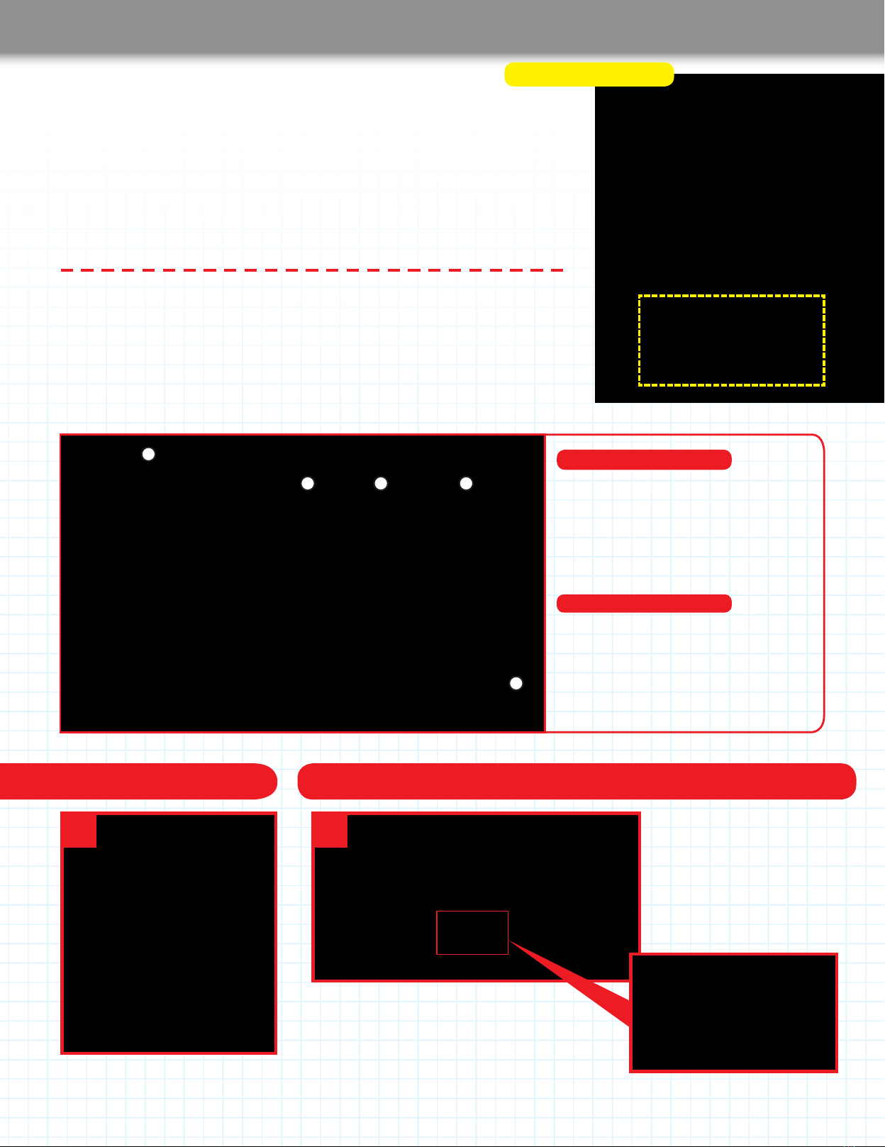
Anything you can
imagine, you
can make!
3D PRINTER
BUILD YOUR OWN
3D technology is
now available for
you at home!

254 255
All rights reserved © 2016
Published in the UK by
De Agostini UK Ltd,
Battersea Studios 2,
82 Silverthorne Road,
Battersea, London SW8 3HE
Published in the USA by
De Agostini Publishing USA, Inc.,
121 E. Calhoun Street,
Woodstock, IL 60098
Stage 41: Add the Z-axis and feeder motor
drivers, and the feeder motor cable
Stage 42: Connect up the power supply and
xittothehousing
Stage 43: Connect the X-, Y- and Z-axis limit
switches to the driver board
Stage 44: Attach two brackets to the housing and
add a linear bush to the modelling table
Stage 45: Add a second linear bush
to the table
WARNING: Not suitable for children under the
age of 14. This product is not a toy and is not
designed or intended for use in play. Items may
vary from those shown.
Thenextvedetailedandeasy-to-followstagesofconstructionforyour3Dprinter.
Assembly Guide 263-279
User Guide Section 1: Download, install and congure
Repetier-Host for the idbox
In this new section of Build Your Own 3D Printer,youwillndouthowto
download and install the software that you need to control the printer. You will
alsoseehowtosetupthesoftwaresoyoucanprintoutyour3Dles
successfully. Plus, how to connect the printer to your computer.
User Guide 255-262
CONTENTS PACK 10
3D PRINTER
BUILD YOUR OWN
TM
www.model-space.com
266-270
271-275
276-277
278-279
263-265

254 255
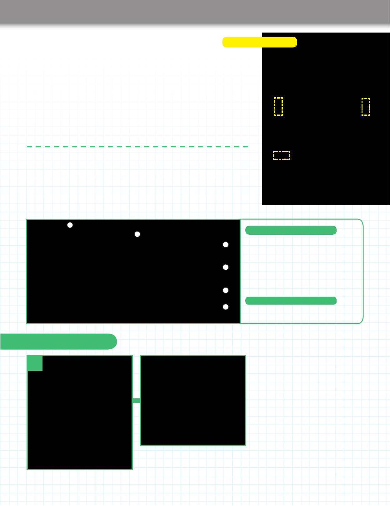
User Guide
User Guide Section 1:
Download, install and congure
Repetier-Host for the idbox
Repetier-Host is a free-to-use piece of
software that is employed around the
worldbypeoplewhoprintoutleson
a3Dprinter–lescreatedon,or
downloaded to, their computers. It can
be set up to work with a wide range of
3Dprintersandoncesetup–whichdoes
nottakeverylong–willmakeprinting
out3Ddesignseasy.Theset-upforthe
idbox is simple and straighforward, and
aftertherstinstallation,itwillnothave
to be done again.
1
In this section, you will download Repetier-Host–thesoftwarethatyourcomputeruses
to communicate with the idbox. You will then set up Repetieranditsbundled‘slicing’
software to work with your idbox.
1. Go to the Repetierwebsite(www.repetier.com)andclickontheFREEDOWNLOADlink.
There is lots of
useful information,
including pages
ofDocumentation,a
Troubleshooting section,
Tutorial pages and a Forum
on the Repetier website.
Preparing to download Repetier-Host
Computer compatibility
3. When you click on this, you
willseethe‘Downloadnow’
page, where you can chose the
version of Repetier-Host
for the operating system
on your computer.
2.You’llbetakentoapage
where you are invited to make
a donation to support the
development of this free-to-use
software. If you do not want to
donate right now, scroll down the
page and you will see a link that
says‘Downloadwithoutdonation’.
2
3
Please check the
specicationofthePCyou
want to connect to the idbox
to see if it is suitable. Below
istheminimumspecications
fortheOperatingSystem
(OS):
Windows 7 or higher
MACOSXorhigher
With older PCs, you may run
into problems, such as slicing
taking a very long time or
the computer crashing when
large or complex objects are
being printed.
256 257
User Guide
Download and install on a Mac
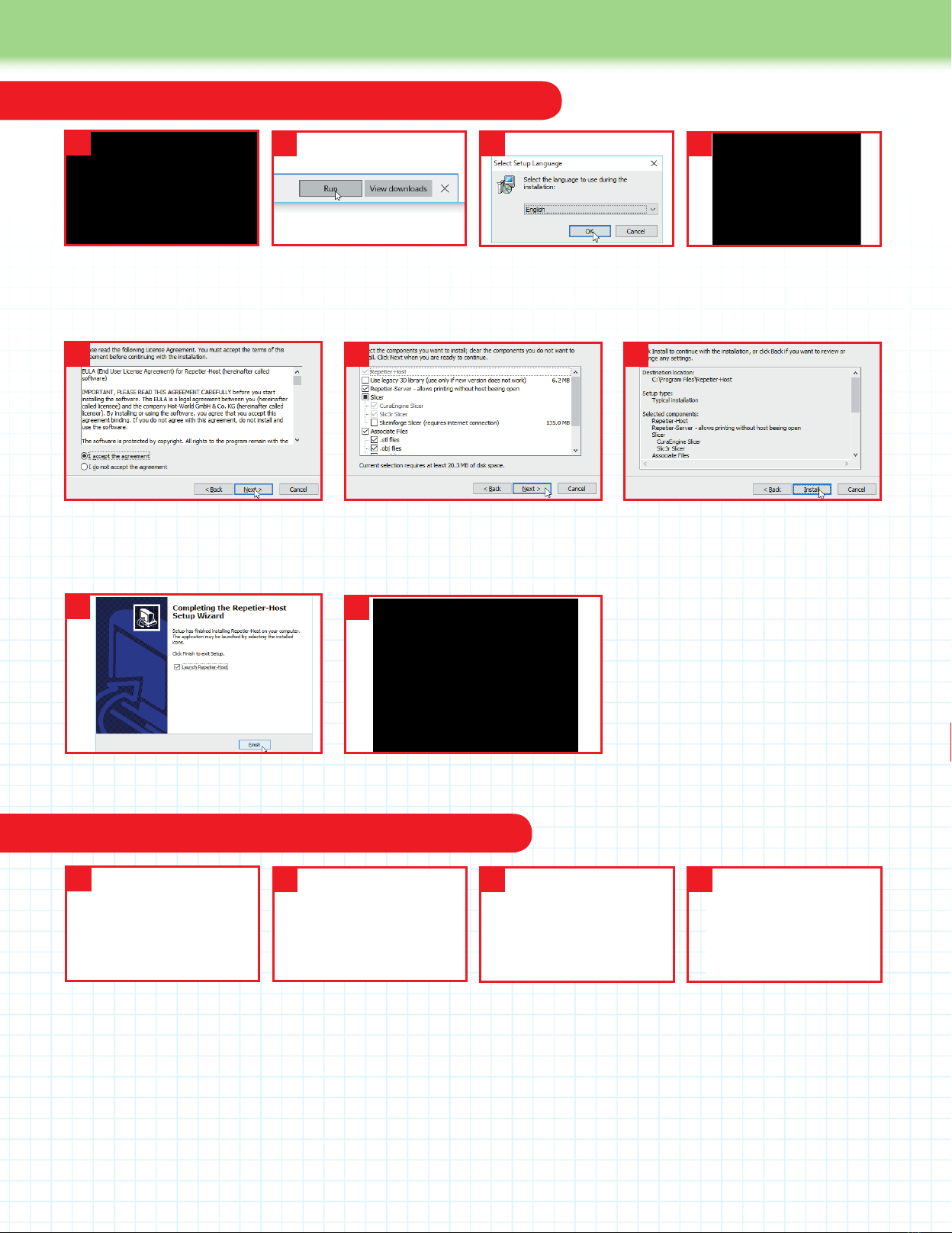
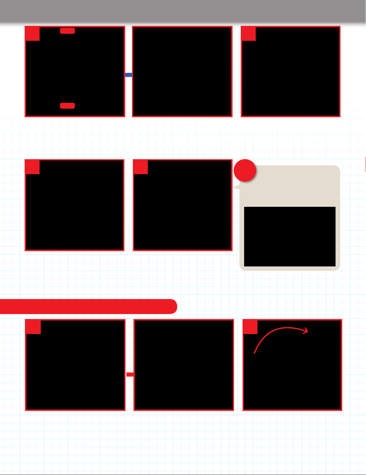
Download and install on a Windows PC
5. In the next dialog window, accept the
LicenseAgreementandclickonNext.The
‘SelectDestinationLocation’dialognow
appears: click Next on it.
6.Onthe‘SelectComponents’dialog
(above)–unchecktheoptiontoinstall
Repetier-Server, then click Next. Click
Next on the Select Start Menu Folder.
1.Onthe‘Downloadnow’
page, click on the link for the
latest version of Repetier-Host
for Windows.
4. This takes you to the
Repetier-Host Setup Wizard.
Click Next to start it.
13
5
2. When it has downloaded,
click Run at the bottom of the
page. Click Yes to allow the app
to make changes to your PC.
2
3. Inthe‘SelectSetup
Language’dialogthat
appears, choose English,
andclickonOK.
6 7
ClickNextonthe‘SelectAdditionalTasks’
dialog.Onthe‘ReadyToInstall’dialog
(above) click on Install. Files will then be
installed on your computer.
8.OntheCompletingtheRepetier-Host
Setup Wizard dialog, click on Finish.
9. The program will launch, showing a
window like the one above.
1. Onthe‘Downloadnow’
page, click on the link for the
latest version of Repetier-Host
for Mac. It will download into
yourDownloadsfolder.When
thedownloadhasnished,
ndtheleinyourDownloads
folder and double-click on it.
4. The program will launch,
showing a screen similar to the
one shown here.
13
8
4
2. A window opens on the
desktop with the Repetier-
Host Mac.app icon in it. In the
Finder, open the Applications
folderviatheGomenu.Drag
the icon into this folder. When
it has copied, double-click its
icon in the Applications folder.
2
3. If the program does not
open, right click (or ctrl click)
on its icon in the Applications
folderandselectOpenfromthe
menu of options that appears.
In the dialog box that then
appears(above),selectOpen.
9
4

256 257
User Guide
Fromthispointon,theUserGuideinstructionsassumethatyouhavenished
constructionoftheidbox.Do notproceedifyouhavenotnishedtheidbox.
Connecting the idbox to your computer
Connecting the power cable
Connecting the idbox to your computer and connecting the power cable
BeforeyoucongureRepetier-Host to work with your idbox, you have to connect the idbox to your
computer using the USB cable. Before you plug in the mains cable to the idbox, there are a couple
of things that have to be done, so do not plug in until you have done these.
Connect the PC and the idbox using the included USB cable.
(Donotpluginthepowercableoftheidboxatthispoint.)Insert
the smaller USB B-type connector into the socket on the right
side of the idbox and the larger USB A-type connector into a
USB port on the PC.
The idbox does not have a power switch, so connecting the
USBcablewillautomaticallyturnontheidbox’scircuitboard.
The circuit board takes its power from the PC via the USB cable
and does not require power from the power plug, which supplies
power to the motors, heater, etc.
The circuit board should be automatically recognised after
plugging in the USB cable. If an error occurs, please recheck
the USB connection, reinstall the driver (if you are using a PC
running Windows) and restart your PC.
Ifthereareerrorsintheassemblyorconguration,
there is a chance that the idbox might suddenly begin
moving when the power cable is connected. If the
idbox suddenly starts moving after inserting the power cable,
immediately remove the power cable. The use of an extension
socket with an on/off switch is recommended.
Donotpluginthepowercableatthispoint.Pleasewait
until after you have followed the instructions set out under
theheading‘Connectingthepowercable’,below.
CAUTION!
CAUTION!
It’snowtimetoconnecttheidboxtoyourcomputerusingtheUSBcable.Ifyouareusingacomputerrunning
Windows,youhavetodownloadandinstalladriver–softwarethatconnectsaPCtoexternaldevices,suchas
printers like the idbox. Mac computers come with the driver pre-installed.
IfconnectingaWindowsPCtotheidbox,downloadArduinoIDE
version 1.0.6 from the website:
https://www.arduino.cc/en/Main/OldSoftwareReleases#previous
Click on the Windows Installer link and follow the instructions to install
the driver. If even after installing Arduino 1.0.6, you have trouble
connectingthePCtotheidbox,downloadandinstallArduinoIDE
version 1.0.5 (available on the same web page). Version 1.0.6 (or
1.0.5) are the recommended versions. Any other versions of the
Arduinodrivershouldbeusedattheuser’sdiscretion.
1. Check that there is at least 5mm of space between the
nozzle and the table (the table and nozzle may be farther apart
depending on the assembly). If the gap is too small, turn the
cup ring on the Z-axis (the silver cylinder) anticlockwise to
lower the table. If the power cable is already connected, the
table will not be movable by hand. Unplug the power cable,
and then operate the table by hand.
2. Move the head by hand toward the centre of the table.
When moving the head by hand, hold it with both hands and
moveitcarefully.AswiththeZ-axisbefore,itwillbedifcultto
move by hand if the power cable is already plugged in. If the
power cable is already plugged in, unplug the power cable
and then operate the head by hand.
Installing the driver software (Windows only)
Before you plug in the power cable
Donotpluginthepowercableuntilafterperformingthetwoproceduresdescribedbelow.Onlyplugitinwhenspecicallyinstructedto
do so. When you plug the power cable into the idbox, this sends power to the various motors and the heater.
After you have performed the procedures described in the box
‘Beforeyoupluginthepowercable’shownleft,youmaynowplug
one end of the power cable into the back side of the idbox and
the other end into a power outlet. (If using an extension cable with
switched sockets, plug the extension cable into a power outlet and
switch on the socket.) When you turn on the power, the head fan
should activate and there should be no sudden movements of the
table or the head.

258 259
User Guide
Before you can use Repetier-Hosttocontroltheoutputfromyouridbox,youhavetoconguretheprogramsoitknowshowtocommunicate
withtheidbox.Itneedstoknowtheidbox’sbedsize,therangeofthemovementsitsprinterheadcandoandthetemperaturesettingsfor
thenozzle.Thesesettingsonlyneedtobeenteredonce.ThewaytosetupRepetiertoworkwithyourcomputerisshownbelow,rstfora
Windows computer and then for a Mac. After this, you check that the computer and idbox are connected properly.
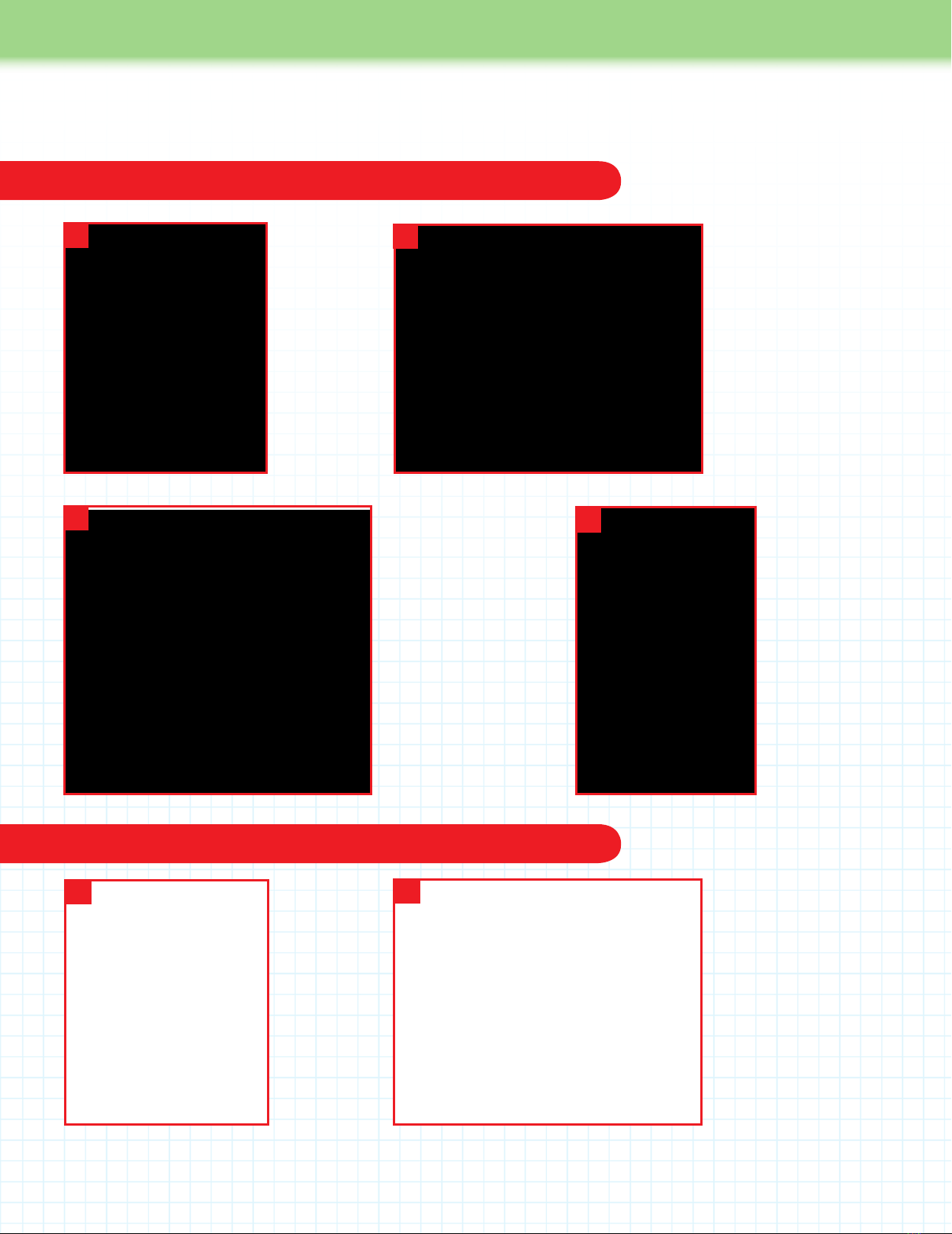
Congure Repetier-Host for a Windows computer
3. Next, you set the number of extruders
and the nozzle size and so on. Click the
Extruder tab. The idbox has a single
extruder, so select 1. The diameter of the
nozzle supplied with the idbox is 0.4mm,
soenterthatasthevaluebyDiameter.
SETTINGS
Number of Extruder: 1
Diameter: 0.4
1. Click the Printer Settings button
onthetoprightofthewindow.Once
the Printer Settings window is open,
click the Connection tab and enter the
values as shown in the image on the left
and in the SETTINGS text on the right.
This procedure should be performed
with as few devices attached to the PC
aspossible.Dependingontheprecise
congurationofyourhardwareand
software, you might also see the setting
for Reset on Connect. If so, set it to
DTRlow->high->low.Thesettingfor
Communication timeout can be left at
the default value.
SETTINGS
Connector: Serial Connection
Port: Auto (If this does not work, test
each of the other options in sequence)
Baud Rate: 115200
Transfer Protocol: Autodetect
Reset on Emergency: Send emergency
command and reconnect
Receive Cache Size: 63
1
3
22. Now click the Printer tab and enter the
values shown in the image on the left
and in the SETTINGS text on the right.
The values here are the recommended
values for the idbox when printing using
PLA.‘DefaultExtruderTemperature’
shouldbesetto220℃,and‘Default
HeatedBedTemperature’shouldbe
setto60℃.Theactualtemperaturesfor
printing will be determined by the printing
temperature upon the start of printing.
Even though the idbox does not have
aheatedbed,youcansetthe‘Default
HeatedBedTemperature’hereanyway.
SETTINGS
Travel Feed Rate: 4800 [mm/min]
Z-Axis Feed Rate: 200 [mm/min]
Manual Extrusion Speed: 2, 20 [mm/s]
Manual Retraction Speed: 5 [mm/s]
Default Extruder Temperature:220℃
Default Heated Bed Temperature: 60℃
Park Position: X:0 Y:0 Z:0
Add to comp. printing time: 10%
Othercheckboxes:(seeimage,left)
Conguring Repetier-Host to work with the idbox
The printer settings that Repetier-Host uses are chosen by selecting a name entered
for the Printer at the top of the Printer settings window. They are stored every time you
clickonOKorApply.Tocreateanewsetofprintersettings,enteranewprintername
in‘Printer’andclickApply.Thenewsettingswillhavewhateverthecurrentvaluesareinthe
PrinterSettingswindow.Youcanthenchangethemifyouwant,andthenclickOK.

258 259
User Guide
Congure Repetier-Host for a Mac computer
4.Clickonthe‘PrinterShape’tabto
enter information about the volume of
the space the idbox can print in. Where
settings are not shown on the right, the
default values can be used.
Onceallvalueshavebeenentered,
clickOKtosavethesettingsandclose
thewindow.ClickingOKwill
save the settings under whatever name
is entered at the top of the window
by‘Printer’.
SETTINGS
X Min: 0 X Max: 150 Bed Left: 0
Y Min: 0 Y Max: 130 Bed Front: 0
Print Area Width: 150 mm
Print Area Depth: 130 mm
Print Area Height: 100mm
4
11.Clickon‘Printersettings’atthetop
right of the Repetier-Hostwindow.Once
the‘Printersettings’windowisopen,click
the Connection tab and enter the values
as shown in the image on the left and in
the SETTINGS text on the right.
If multiple ports are available for
selection in the Port dropdown menu,
select any one for now. The values
available may not contain the one shown
in the image on the left, depending on
the Mac being used.
SETTINGS
Port: usbmodem****
(**** will change depending on the Mac
being used.)
Baud rate: 115200
Stop Bits: 1
Parity: None
Transfer Protocol: Autodetect
Receive cache size: 63
22. Click the Behaviour tab and enter the
values as shown in the image on the left
and in the SETTINGS text on the right.
The values here are the recommended
values for the idbox when printing using
PLA.‘DefaultExtruderTemperature’–
shouldbesetto220℃,and‘Default
heatedbedtemperature’shouldbeset
to60℃.Theactualtemperaturesfor
printing will be determined by the printing
temperature upon the start of printing.
Even though the idbox does not have
aheatedbed,youcansettheDefault
Heated Bed Temperature here anyway.
SETTINGS
Travel Feedrate: 4800 [mm/min]
Z Axis Travel Feedrate: 200 [mm/min]
Default Extruder Temperature:220℃
Default heated bed temperature:60℃
Number of Extruder: 1
Check Extruder & Heated bed
every 1 seconds
Dump area positon: X= 5 Y= 5
Z-min= 0
Add to comp. printing time: 10%
Othercheckboxes:(seeimage,left)
260 261
User Guide
3
4. You now save the new settings and
give them a new name. Click the Add
button on the top row of the Printer
Settings window.
4
5. A dialog box appears. Enter a new
name, such as idbox, and click Create.
56
6. Click the OK button at the bottom of
the Printer Settings window.
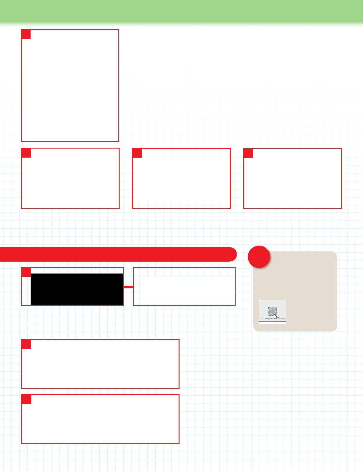
Check the connection between the computer and the idbox If at any point from now
on, the idbox goes out
of control, press the
Emergency Stop button (Windows
version is shown, but Mac version
is virtually identical) to immediately
terminate all
movement. If the
idbox still does not
stop, unplug the
power cable.
CAUTION!
1
1. To check that the software on your computer is ‘talking’ to the idbox, click on the red
Connect button at the top left of the screen. The Windows version is shown above left and
the Mac version above right.
2. Attempting to connect to printer. Connection opened.
If the connection is successful, a message similar to the
one above should be visible in the log. The version shown is
for Windows, but is similar on the Mac. If you can’t see any
message, click on Toggle Log (Windows) or Load G-Code
(Mac). These are close by the Connect button at the top left
of the screen (See above).
3. There could be several reasons why you see an error
message. The USB cable might not be plugged in properly, the
correct driver (Windows) might not be installed or the wrong
Port might have been chosen in the Printer settings. Check
that the USB cable is in OK, reinstall the driver and restart your
Windows PC. Alternatively, select a different port on the Mac or
Windows PC and try each one until one of them works.
2
3
Attempting to connect to printer. Couldn’t open port for device
If a message like this appears, there is a problem with the connection.
idbox
3. SET THE PRINTABLE AREA
Now click on the Dimension tab to enter
information about the volume of the
space the idbox can print in. Use the
values as shown in the image on the left
and in the SETTINGS text on the right.
SETTINGS
Home X: x min
Home Y: y min
Home Z: z max
X Min: 0 [mm] X Max: 150 [mm]
Y Min: 0 [mm] Y Max: 130 [mm]
Printer type: Classic Printer
Print Area Width: 150 [mm]
Bed Front: 0 [mm]
Print Area Depth: 130 [mm]
Bed Left: 0 [mm]
Print Area Height: 100 [mm]
260 261
User Guide
Setting up the CuraEngine slicer for Windows computers
Setting up the Slic3r slicer for Mac computers
Setting up the slicing software for the idbox
Toconvert3Ddataintothecommandsthatcontrola3Dprinter(G-code),youuseaprogramcalledaslicer.Repetier-Host has
different slicers included with it. We will use CuraEngine for Windows and Slic3r for Mac computers.
1.Open
Repetier,
and click on
the Slicer tab
near the top
right of the
screen. Select
CuraEngine
from the drop-
down list by
Slicer: and
then click the
Conguration
button.
2.Ontheleftofthescreen,
select the Print, then Speed
and Quality tabs. Enter the
values shown in the image
on the left for both the
Speed and Quality sections.
The values entered for the
speed determine the speed
of the movement of the
head when printing using
CuraEngine, and the values
for the Quality determine
the height of each layer
when printing.
3. Click the Filament tab
to enter the details of the
lament.(Detailshereare
forPLA.)Notethesetting
by Temperature will change,
dependingonthelament
you are using. To save
settingsforalament,
clickthe‘Saveas…’button
near the top of the pane,
and enter a name for the
lament,suchasPLA,then
clickOKtosaveit.Ignore
the settings in the Cooling
section, as the idbox does
not use them.
12
34. The settings
can be selected
on the right of
the screen. If you
have not changed
the name of the
settings, these
will show as
Defaultin‘Print
Conguration’,
0.2mmin‘Quality’
andDefaultin
‘Extruder1:’.
4
1. Click the
Slicer tab in
the Repetier
window to
open the Slicer
panel, then
clickCongure
to open the
conguration
window for
Slic3r.
12.Underthe‘PrintSettings’
tab,clickon‘Layersand
perimeters’inthepanelon
the left. Enter the values
as shown in the image on
the left for the two settings
shown under SETTINGS
below.
SETTINGS
Layer height: 0.2 mm
First layer height:
0.2 mm or %
2

262 263
Assembly Guide
User Guide
262 263
3. Click on Speed in the panel on the
left and enter the values as shown
in the image on the left and under
SETTINGS below.
To save the Print Settings, click
theoppydiskicononthetopleft
of the window. In the dialog box that
appears,enteraname,suchas‘test
print’,thenclickOK.
SETTINGS
Perimeters: 30 mm/s
Small perimeters: 30 mm/s or %
External perimeters:
70% mm/s or %
Inll: 60 mm/s
Solid inll: 60 mm/s or %
Top solid inll: 50 mm/s or %
Support material: 60 mm/s
Bridges: 60 mm/s
Gap ll: 20 mm/s
Travel: 130 mm/s
First layer speed: 30% mm/s or %
All the values under Acceleration
control (advanced) are set to
0 mm/s2
4. Click on the Filament Settings
tab, and on Filament in the panel on
the left. Enter the values as shown
in the image on the left and under
SETTINGS right. The values under
Temperature used here are for
PLAandwillneedtobechanged
dependingonthetypeoflament
you use. Save the settings as
you did in Step 3 above, this time
enteringanamesuchasPLA.
SETTINGS
Diameter: 1.75 mm
Extrusion multiplier: 1
Extruder: First layer: 220 Other
layers: 220
Bed: First layer: 0 Other layers: 0
7. Click the close button on the top left of the Slic3r window, to return to
Repetier. To use the settings, select the names you used for them in the three
eldsoutlinedinredintheimageontheleft.Thenamesoftheeldsare:
Print Settings:
Printer Settings:
Extruder 1:
6. Click Extruder 1 in the panel on
the left sidebar. Enter the values as
shown in the image on the left and
under SETTINGS below. Save the
settings as you did in Step 3
above, this time entering a name,
such as idbox.
SETTINGS
Nozzle diameter: 0.4 mm
Extruder offset: x: 0 y: 0 mm
Length: 1 mm (zero to disable)
Lift Z: 0 mm
Speed: 30 mm/s
Extra length on restart: 0 mm
Minimum travel after retraction:
2 mm
Retract on layer change: (check)
Wipe while retracting: (leave
unchecked)
(‘Wipewhileretracting:’mightnotbe
visible, depending on the version of
Slic3r that you have installed.)
Length: 10 mm (zero to disable)
Extra length on restart: 0 mm
5. Click on the Printer Settings tab, and
then on General in the panel on the left.
Enter the values as shown in the image
on the left and under SETTINGS below.
SETTINGS
Bed size: x: 150 y: 130 [mm]
Printer center: x: 75 y: 65 [mm]
Z offset: 0 [mm]
G-code avor: RepRap (Marlin/
Sprinter)
(If the exact above option shown by
‘G-codeavor’aboveisnotoffered,
select one that includes RepRap.)
Use relative E distances: (leave
blank)
Extruders: 1 (Number of nozzles)
Use rmware retraction: (leave
unchecked)
(Theoptiontoalterthe‘Usermware
retraction:’settingmightnotbevisible
depending on the version of Slic3r
that you have installed.)
Vibration limit: 0 Hz
3
4
5
6
7
Your 3D Printer User Guide will be continued in the next pack!

262 263
Assembly Guide
262 263
Stage 41: Add the Z-axis and
feeder motor drivers, and
the feeder motor cable
The two motor drivers you add to the
driver board this time are identical to
each other and also to the two you added
in Stage 39. This time the motor drivers
are for the Z-axis and feeder motors.
Remember to make sure they are fully
seated and that they are plugged in
the right way round. You then secure
the feeder motor cable to the housing
and plug it into the driver board. Finally,
connect your PC to the circuit board
using the USB cable.
1: Motor drivers x 2
2: Feeder motor cable (650mm) x 1
3: Cable ties x 4
4: USB cable x 1
Stage 41 Components
In this stage, you add the Z-axis motor driver to the driver board, then add the feeder
motor driver before plugging the feeder motor cable into the driver board.
You will need
Ruler
Marker pen
Scissors
PC to connect to idbox via USB cable
Parts to have ready
1 2
Get ready the printer housing and
turn it so that the front is facing you.
Have a look at the driver
board and the diagram,
left–makesureyou
know where to plug in the
Z-axis motor driver and
the feeder motor driver.
Locatethefeedermotor
cable plug, below.
Z-axis motor driver
goes here
Feeder motor driver
goes here
Feeder motor cable plug
123 4
Stage 41 Assembly Area

264 265
Assembly Guide
264 265
3
4
Hold one of the motors drivers as shown and plug it into the position for the Z-axis motor driver (see
previous page, Step 2). Make sure that the circular structure on the driver is aligned as shown above.
Holdthedriverparalleltothedriverboardwhileyouplugitinslowlyandrmlyuntilitisinalltheway.
Now plug the other motor driver into the position for the feeder motor driver. Again, press
rmlywhileholdingitparalleltothedriverboarduntilitisfullyinserted.
Plug the motor drivers into the driver board
Ensure the driver motors are not
at an angle to the driver board and
that the pins are all the way in.
Make sure that the
circular element on
the top of the motor
driver is on the left when
viewed with the front of the
housing facing you.
Be careful not to touch
this element.
Make absolutely certain that
the motor drivers are correctly
plugged in, with their pins in the
correct sockets and the circular structures
to the left.
Failure to
do so might
result in
reduring
operation of
the printer.
Circular element
Attach the feeder cable to the housing, then plug it into the driver board
5 6
With a marker pen, make a mark on the
feeder motor cable 12cm in from the end
of the cable, measuring from the smaller
(motor end) connector.
Turn the housing so the rear panel is facing you. Put a cable tie through each of the four
sets of holes outlined in red in the image above left. Align the tie at the top right with the
mark on the feeder motor cable and, with the motor end socket on the right, tighten the
cable tie around the cable. Trim off the excess cable tie with scissors.
Align with
12cm mark
CAUTION!
CAUTION!
264 265
Assembly Guide
264 265
789
At the other three cable tie positions
(outlined in red, above), use the cable ties
to secure the feeder motor cable and the
spiraltubetothehousing.Whenyou’ve
done up each cable tie, trim off the excess
with scissors.
Pass the feeder motor cable through
the hole in the casing to the left of the
noiselter.
Turn the housing so the front is facing you.
Untwistthefeedermotorcableyou’vejust
passed into the housing (if necessary) and
plug the connector into the pins (outlined
in yellow, above) on the motor board for
the feeder motor cable.
The Z-axis motor and feeder motor
drivershavebeenttedtothedriver
board and the feeder cable has
been plugged into the driver board.
There are two different connectors
on the USB cable supplied this
time. The smaller, squarer one is
the B-type and is plugged into the idbox.
Thewider,atteroneistheA-type,andthis
is plugged into the USB port on a computer.
Check the power supply from a computer to the circuit board
10
12
11
With the right side of the printer facing you,
plug the B-type connector of the USB cable
into the USB port on the circuit board.
The circuit board is powered
via the USB cable by your computer.
When you connect the USB cable
to your computer you should see a
green light come on on the circuit
board (lower photo). Check this, then
remove the USB cable and keep it
safe.
With your computer turned on, plug the
A-type USB connector into a USB port on
the computer.
Plug in
Plug in
USB
symbol
B type B type
A type A type
Stage
nished
266 267
Assembly Guide
266 267
The power supply has no fewer than
nine terminals to which you attach cables
in this stage. After wiring up the power
supply, you attach it to the inside of the
base of the housing and connect it to the
thick power cables, the fan cables and
thenoiselter.Makesureyoufollowthe
instructions carefully and be sure to check
over your assembly so you can be certain
that the cables are all connected properly.
This is extremely important, as if the
cables are not correctly wired up, there is
a real danger that the printer will fail when
the power is switched on.
Parts to have ready Set the input voltage to 230V (for UK)
1
The printer housing.
1: Power supply x 1
2: Power lines x 2
3: Earth wire x 1
4: Power supply wires for the fans x 2
5: M3 truss head screws x 4
Stage 42 Components
In this stage, you will wire up the power supply, then attach it to the housing. After that,
connect up more of the wiring inside the housing. It is vital to get the wires connected
properly, so take care as you do it.
You will need
Phillips screwdriver size 1
Phillips screwdriver size 2
Stage 42: Connect up the power
supply and x it to the housing
Stage 42 Assembly Area
1
2 3 4
5
2
There is a switch on the side of the power supply
where you can select the input voltage from the
mainstothepowersupply.FortheUK,makesure
it is switched to 230V and not 115V.
Incorrect

266 267
Assembly Guide
266 267
Connect up the nine screw terminals on the power supply
Plug the second of the two yellow power
lines into the terminal with the letter N
above it and tighten the screw.
Plug the green Earth cable into the
terminal with the Earth symbol above it
and tighten the screw.
Plug the black wire for the fan power supply
line into the fourth terminal from the left,
whichhasCOMaboveit.Putthepinkwire
into the seventh terminal, which has +V
above it. Tighten the screws.
567
Black
wire
Pink
wire
Earth symbol
3
There are nine screw terminals on the end of the power supply. Use a size 2 Phillips screwdriver to
loosen them all before you start attaching cables.
9 screw
terminals
Gap when
screw is
loosened
When you insert
the Y-shaped end of a cable
into a screw terminal, do it so
the crimp mark is uppermost
so it goes in securely.
4
Plug the Y-shaped end of one of the yellow power lines into the terminal on the left with the
letterLaboveit.Tightenthescrewoftheterminalwiththescrewdriver.
Plug in
Crimp
mark
268 269
Assembly Guide
268 269
Attach the power supply to the housing
12 13
Passthepowersupplythroughthefrontpanel(you’llhavetoangleittogetitthrough).
Make sure the cables do not go under the power supply, and beware of damaging the
housing while you manoeuvre the power supply.
With the front panel facing you, rotate
the housing by 90 degrees so it lies on
its right panel. Support the power supply
while you do this.
Rotate by 90
degrees
8 9
Turn the housing so its left side is facing you. Place the power supply as shown, so it is
to the right of the housing. Pass the rightmost of the two thick pink power cables from
the driver board through the opening in the front panel of the housing and plug it into the
rightmost terminal of the power supply, which has +V above it, and tighten the screw.
Pass the second thick pink cable from the
driver board through the hole in the front
panelandplugitintothepowersupply’s
eighth terminal from the left, which has a
+V above it, and tighten the screw.
Left
Right
It is very important that the wires
connected to the power supply
are in the correct terminals. Check
particularly that the pink and black wires are
in the correct positions as shown below.
10 11
Take the rightmost of the two thick black
cables from the driver board and plug it
into the sixth from the left of the power
supply’sterminals,whichhasCOMabove
it, and tighten the screw.
Take the other thick black cable from
the driver board and plug it into the
fthfromtheleftofthepowersupply’s
terminals,whichhasCOMaboveit,
and tighten the screw.
CAUTION!

268 269
Assembly Guide
268 269
17 18
Hold the power supply in position with one hand so that the four screw holes in its
underside align with the screw holes in the bottom panel (ringed in red). Insert an 8mm
M3trussheadscrewintoeachofthescrewholesandscrewtheminwithyourngers.
Plug the connector of the green Earth wire
onto the central, upper metal pin on the
noiselter.
Tuck the four thick power cables (two black, two pink) into the bottom of the housing, as
shown above left and above right. If you unplug any of the connectors from the driver
board while you do this, make sure you get them back into the correct locations.
Tighten all four of the screws with a size 1
Phillips screwdriver.
When tidying the thick power
cables to the bottom of the
housing, unplug the motor cables
one at a time and plug them back in as
soon as you can to avoid mixing them up.
Connect the remaining cables
16
Turn the housing so its base is back on your work surface. Plug the two yellow power
supplylinesasshownaboveontothetwolowerterminalsofthenoiselter,whichisat
therearleftofthehousing.Pushthemallthewayon,rmlyyetgently.
Thenoiselterhas
threemetalpins.Ofthese,
two are side by side and have
a black cover to their bases.
These are the pins for the
power lines. The other pin is for
the Earth wire. Make sure you
plug the correct wires onto the
correct pins.
Earth
wire
Power
lines
14 15
Plug on
Plug on

270 271
Assembly Guide
270 271
The power supply terminals
have been wired up, and the
powersupplyhasbeenxed
inside the housing.
19
Take the connector for one branch of the fan power supply wires, and plug it into the connector for the fan at
the lower back right of the housing. (The connector leading to the fan can be connected to either branch.)
The fan power
connectors
are designed to be
put together so the
ribs on one side of the
smallerconnectorst
into the slots on the
larger connectors.
20
21
Plug the connector for the fan in the printer head into the connector on the other
branch of the power supply wires.
In the photo, you can see
where the various cables you
have connected up in this
stage run from and to. In the
next stage, more cables are
added, and the wiring is tidied
up with cable ties.
Slots Ribs
Correct
Incorrect
Stage
nished
270 271
Assembly Guide
270 271
Stage 43: Connect the
X-, Y- and Z-axis limit
switches to the driver board
When you insert the pins on the limit
switches into the connectors on the
ends of the cables, be sure to do this
carefully and not bend the pins. Make
sure you get the connectors in the
correct positions on the driver board.
Secure the limit switch cables using
ties supplied with this stage and others
attached to the housing in Stage 39. After
you have plugged the thermistor cable into
the driver board, tidy up the cables in the
bottom of the housing.
1:Limitswitchcablesx2
2: Cable ties x 6
3: Brackets x 2
4: M3 truss head screws (14mm) x 2
5: M3 washers x 2
6: M3 nuts x 2
Stage 43 Components
In this stage, you connect up the three limit switches to the driver board using the two
cables supplied with this stage and the one supplied with Stage 3. You will also plug in
the thermistor cable to the driver board and tidy up the cables.
Tools you will need
Scissors
Parts to have ready
1
Get ready the printer housing and the limit
switch cable that was supplied with Stage 3.
Stage 43 Assembly Area
1
2
3
4
5
6

272 273
Assembly Guide
272 273
2 3
The Z- and X-axis limit switches are at the rear
and the Y-axis limit switch is on the right.
ConnecttheX-axislimitswitchrst.Turnthecable’s
connector so that you can see the side where the
metal parts show. Plug it in carefully from below until
justthebasesoftheswitch’spinsarevisible.
Connect the cables to the limit switches
Plug in
The sides of the
connectors are
different. Make
sure you plug them in so
the metal parts show.
X-axis limit
switch
Metal shows
on this side
Z-axis limit
switch
Y-axis limit
switch
Pin
base
You must get
the connectors from the
limit switches plugged into
the correct sets of pins or
the printer will not operate
properly.Takecare!
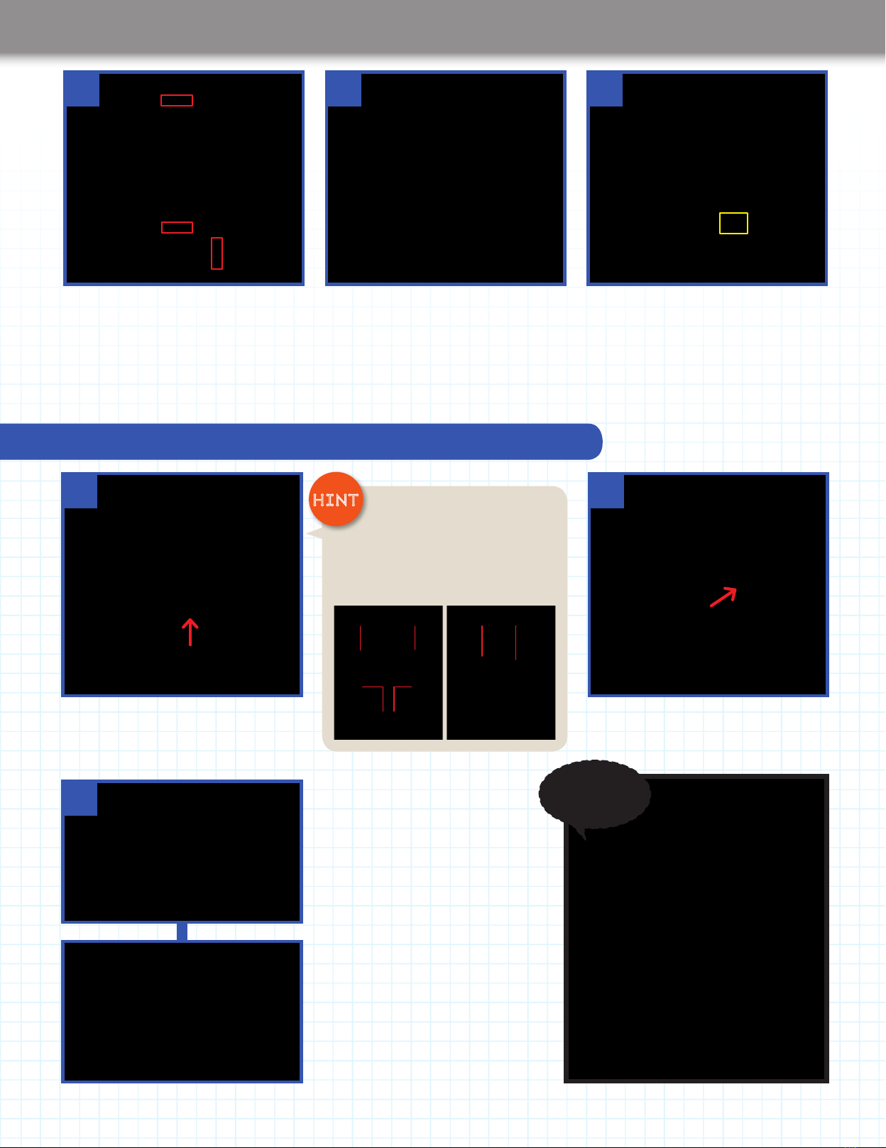
6
Turn the printer housing so the front panel is facing you and
ndthelocationofthepinsforthelimitswitchcables,outlined
in yellow above, and shown in close-up on the right.
Connect the limit switch cables to the driver board
Z-axis
(6th column
from right)
Y-axis
(3rd column
from right)
X-axis
(1st column
on the right)
4 5
Now connect the Z-axis limit switch. Carefully
plug the pins on the switch into the sockets on
the connector, making sure the metal parts of
the connector are visible, as shown above.
Turn the printer housing so its left side is
facing you, and plug in the Y-axis limit switch
cable connector from below. Again, put in the
connector so its metal parts are showing.
Plug in
Plug in
Pins on switch
Pins on switch
Connector's metal parts
Connector's
metal parts
Connector's
metal parts
Table of contents


