Intamsys Funmat Pro 410 User manual

FUNMAT PRO 410 3D PRINTER
User Manual
Version: July 2, 2020


1
ONTENTS
1 SERVICE AND SUPPORT ................................................................................................................................ 1
1.1 SERVICE ................................................................................................................................................................. 1
1.2 SAFETY INSTRUCTIONS .......................................................................................................................................... 1
1.2.1 CLASSIFICATION OF HAZARDS .......................................................................................................................................... 1
1.2.2 POTENTIAL SAFETY HAZARD AREA .................................................................................................................................... 2
1.3 DOOR LOCK ........................................................................................................................................................... 2
1.4 ENVIRONMENTAL REQUIREMENTS ....................................................................................................................... 3
2 SETUP AND INSTALLATION ........................................................................................................................... 5
2.1 GENERAL INFORMATION ....................................................................................................................................... 5
2.1.1 ATTACHMENT TOOLS......................................................................................................................................................... 5
2.1.2 WORKING SPACE REQUIREMENTS..................................................................................................................................... 5
2.1.3 INSPECTION OF THE PRINTER'S NAMEPLATE .................................................................................................................... 5
2.2 MACHINE PREPARATION ...................................................................................................................................... 6
2.2.1 REMOVE PACKAGE ............................................................................................................................................................. 6
2.2.2 TAKE OUT THE ACCESSORIES ............................................................................................................................................. 7
2.2.3 RELEASE THE FIXATION OF XY AXIS .................................................................................................................................. 8
2.2.4 ADD LIQUID COOLANT ...................................................................................................................................................... 8
2.2.5 INSTALL THE PRINTING BUILDPLATE .................................................................................................................................. 9
3 SYSTEM COMPONENTS ............................................................................................................................... 11
3.1 OVERVIEW OF THE PRINTER ................................................................................................................................ 11
3.2 TOP DOOR SUBASSEMBLY .................................................................................................................................. 12
3.3 PRINTING CHAMBER SUBASSEMBLY ................................................................................................................... 13
3.4 MATERIAL CHAMBER SUBASSEMBLY .................................................................................................................. 13
3.5 PRINTING HEAD SUBASSEMBLY .......................................................................................................................... 14
3.6 XY AXIS SUBASSEMBLY....................................................................................................................................... 15
3.7 Z AXIS SUBASSEMBLY ......................................................................................................................................... 16
3.8 CASTERS .............................................................................................................................................................. 16
4 USER INTERFACE ........................................................................................................................................... 17

2
4.1 OVERVIEW ........................................................................................................................................................... 18
4.1.1 STATUS BAR ...................................................................................................................................................................... 19
4.1.2 NAVIGATION BAR ............................................................................................................................................................. 21
4.1.3 DISPLAY AREA ................................................................................................................................................................... 21
4.2 PRINT INTERFACE ................................................................................................................................................ 21
4.2.1 MAIN STATE AREA ............................................................................................................................................................ 22
4.2.2 AUXILIARY STATE AREA .................................................................................................................................................... 23
4.2.3 CONTROL AREA ................................................................................................................................................................ 24
4.3 TUNING INTERFACE ............................................................................................................................................. 26
4.4 INCHING INTERFACE ............................................................................................................................................ 26
4.5 MATERIAL INTERFACE ......................................................................................................................................... 27
4.5.1 NOZZLE SETTING AREA .................................................................................................................................................... 28
4.5.1 MATERIAL MANAGEMENT INTERFACE ............................................................................................................................ 28
4.6 SYSTEM INTERFACE ............................................................................................................................................. 29
4.7 OTHER INTERFACES ............................................................................................................................................. 31
4.7.1 REMOTE PRINTING INTERFACE ........................................................................................................................................ 31
4.7.2 WIRED NETWORK IP SETTING INTERFACE ...................................................................................................................... 31
4.7.3 WIRELESS NETWORK IP SETTING INTERFACE ................................................................................................................. 32
5 PRINTER OPERATION .................................................................................................................................... 36
5.1 BASIC USER OPERATIONS ................................................................................................................................... 36
5.1.1 POWER ON THE PRINTER ................................................................................................................................................. 36
5.1.2 POWER OFF THE PRINTER ................................................................................................................................................ 37
5.2 MATERIAL, MATERIAL CHAMBER AND NOZZLE ................................................................................................. 37
5.2.1 MATERIAL LOADING ......................................................................................................................................................... 37
5.2.2 MATERIAL UNLOADING ................................................................................................................................................... 39
5.2.3 MATERIAL EDITING ........................................................................................................................................................... 40
5.3 REPLACEMENT OF NOZZLE OR MATERIAL .......................................................................................................... 41
5.3.1 REPLACEMENT OF NOZZLE .............................................................................................................................................. 41
5.3.2 MATERIAL CHANGE BEFORE PRINTING ........................................................................................................................... 42
5.3.3 PAUSE TO CHANGE MATERIAL ........................................................................................................................................ 43
5.3.4 REPLENISH MATERIAL AFTER STARVED FEEDING ALARM ............................................................................................... 43
5.4 BASIC PRINTING OPERATIONS ............................................................................................................................ 43
5.4.1 PREPARE THE PRINTER ..................................................................................................................................................... 43
5.4.2 IMPORT THE PRINT FILE INTO THE PRINTER .................................................................................................................... 44

3
5.4.3 LOAD THE PRINT FILE ....................................................................................................................................................... 45
5.4.4 PRINTING PROCESS .......................................................................................................................................................... 46
5.4.5 SETTING OF PRINTING PARAMETERS ............................................................................................................................... 47
5.4.6 PRINTING ALARM ............................................................................................................................................................. 47
5.4.7 PAUSE THE PRINTING ....................................................................................................................................................... 48
5.4.8 CEASE THE PRINTING ....................................................................................................................................................... 48
5.4.9 AFTER THE COMPLETION OF PRINTING .......................................................................................................................... 48
5.5 CHANGE DEFAULT SETTINGS OF THE PRINTER ................................................................................................... 49
5.5.1 CHANGE THE SYSTEM DATE AND TIME ........................................................................................................................... 49
5.5.2 ENABLE/DISABLE THE FUNCTION OF ALLOWING NETWORK REMOTE ACCESS ............................................................ 50
5.5.3 ENABLE/DISABLE WIFI AUTO-RECONNECT .................................................................................................................... 50
5.5.4 ENABLE/DISABLE DEVELOPER MODE .............................................................................................................................. 50
5.5.5 ENABLE/DISABLE USB PRINTING MODE ......................................................................................................................... 50
5.5.6 LOCK THE FRONT DOOR AND CAP ................................................................................................................................. 51
5.5.7 LIQUID COOLER CONTROL .............................................................................................................................................. 52
5.5.8 ENABLE MOTOR................................................................................................................................................................ 52
5.6 PRINTER STATE.................................................................................................................................................... 53
5.6.1 TEMPERATURE AND HUMIDITY STATE ............................................................................................................................. 53
5.6.2 MATERIAL STATE .............................................................................................................................................................. 53
5.6.4 STATE OF LIQUID COOLING SYSTEM ............................................................................................................................... 54
5.6.4 SOFTWARE VERSION ........................................................................................................................................................ 54
6 LEVELING AND CALIBRATION ................................................................................................................... 55
6.1 MANUAL LEVELING AND XYZ CALIBRATION ..................................................................................................... 55
6.1.1 MANUAL LEVELING .......................................................................................................................................................... 56
6.1.2 Z CALIBRATION ................................................................................................................................................................. 56
6.1.3 XY CALIBRATION .............................................................................................................................................................. 57
6.2 AUTO LEVELING AND XYZ CALIBRATION ............................................................................................................ 59
6.2.1 AUTO LEVELING ................................................................................................................................................................ 60
6.2.2 Z CALIBRATION ................................................................................................................................................................. 61
6.2.3 XY CALIBRATION .............................................................................................................................................................. 61
6.3 CALIBRATION OF MATERIAL WEIGHT ................................................................................................................. 61
6.4 CALIBRATION OF THE CLAMP FORCE OF EXTRUDER ........................................................................................... 62
7 MAINTENANCE ................................................................................................................................................. 65

4
7.1 INSPECTIONS BEFORE EACH PRINT ..................................................................................................................... 65
7.1.1 INSPECT THE PRINTING BUILDPLATE ............................................................................................................................... 65
7.1.2 EMPTY THE PRINTING CHAMBER ..................................................................................................................................... 65
7.1.3 INSPECT NOZZLES ............................................................................................................................................................ 65
7.2 MAINTENANCE AFTER EACH PRINT .................................................................................................................... 65
7.2.1 CLEAN THE GLASS BUILDPLATE ....................................................................................................................................... 65
7.2.2 CLEAN AND REPLACE THE NOZZLE BRUSH ..................................................................................................................... 65
7.2.3 CLEAN THE CHAMBER ...................................................................................................................................................... 66
7.2.4 CLEAN THE NOZZLE ......................................................................................................................................................... 66
7.3 PERIODIC MAINTENANCE ................................................................................................................................... 66
7.3.1 CLEANSING OF THE FEEDING GEAR OF EXTRUDER ......................................................................................................... 66
7.3.2 MAINTENANCE OF MOVING PARTS ................................................................................................................................ 67
7.3.3 MAINTENANCE OF CHAMBER FILTER SCREEN ................................................................................................................ 67
7.3.4 MAINTENANCE OF FEEDING PIPE AND COOLING PIPE .................................................................................................. 67
7.3.5 LIQUID COOLANT ............................................................................................................................................................. 68
7.4 OTHERS ............................................................................................................................................................... 68
8 TROUBLESHOOTING ..................................................................................................................................... 69

1 SERVICE AND Support
1
1 Service and Support
The information in terms of service and support for FUNMAT PRO 410, as well as the safety information
and safety label position are provided in this chapter.
1.1 Service
Please contact INTAMSYS customer support for any problem not covered by this guide during your use of
the printer.
Region E-mail Tel.
Asia Pacific Support_APAC@intamsys.com +86-21-5846 5932
Europe, Middle East and Africa Support_EMEA@intamsys.com +86-21-5846 5932
North America / Latin America Support_America@intamsys.com +86-21-5846 5932
1.2 Safety Instructions
Following basic safety instructions are provided to ensure the safe installation, operation and
maintenance of INTAMSYS equipment, which shall not be regarded as the comprehensive safety
problems. FUNMAT PRO 410 Printer is a safe and reliable 3D printer in industrial grade. There is potential
hazard in the printer overhauling area.
1.2.1 Classification of hazards
It is recommended by INTAMSYS that all services should be executed by qualified personnel. All
personnel operating the printer or near by the printer shall understand the meaning of following hazard
classification used in this guide.
[HIGH VOLTAGE]: The sign of high voltage indicates the existence of high voltage. Be sure to keep away
from exposed circuits. It is suggested to take off all accessories.
[HIGH TEMPERATURE]: It indicates that the equipment is in high temperature. Take extra care when
working near by heated components. Be sure to wear the safety gloves provided in the attachment tools.
The temperature of printing nozzle in the printer can reach up to 500℃.
The temperature of printing buildplate in the printer can reach up to 160℃.
The temperature of chamber in the printer can reach up to 90℃.

1 SERVICE AND SUPPORT
2
[PINCH POINT]: It indicates that you may have a risk to pinch hand between two objects. There are one
or multiple objects moving in your working area.
1.2.2 Potential safety hazard area
The following components and areas have been highlighted as having potential safety hazard. Failure to
follow the safety procedure will cause system fault or problem in reliability.
Nozzle
[HIGH TEMPERATURE] Warning: During the heating of nozzle, please be sure to wear the safety gloves
when maintaining the nozzle or working in the chamber.
Printing buildplate
[HIGH TEMPERATURE] Warning: During the heating of hot bed, please be sure to wear the safety gloves
when taking off the buildplate glass or working in the chamber.
Chamber
[HIGH TEMPERATURE] Warning: During the heating of chamber, please be sure to wear the safety
gloves when working in the chamber.
XY movement frame
[PINCH POINT] Warning: Do not wear tie, loose clothes or hanging ornament when working near by any
moving component of the printer.
Take extra care when maintaining such moving components.
Z-axis buildplate
[PINCH POINT] Warning: Do not wear tie, loose clothes or hanging ornament when working near by any
moving component of the printer.
Don’t put anything on the bottom of the chamber.
1.3 Door lock
The sensor is used to transmit the state of chamber front door and top door. For safety reason, the
chamber front door and top door must be closed before the chamber is heated or the X/Y/Z motor starts
working. The electromagnetic lock can ensure that the chamber door and cap are firmly closed when the
printer is executing the printing operation.

1 SERVICE AND Support
3
1.4 Environmental Requirements
• The printer is for indoor use only.
• The condition of air quality with excessive solid particles (conductive or non-conductive) may
cause damage to the system.
• The system operating temperature shall be kept between 15°C and 30°C (59°F to 86°F), and the
relative humidity shall be kept between 30% and 70% (non-condensate).
• The system storage temperature shall be kept between 0°C and 35°C (32°F to 95°F), and the
relative humidity shall be kept between 20% and 90% (non-condensate).
•
•
• Please take attention that changes or modification not expressly approved by the party
responsible for compliance could void the user’s authority to operate the equipment.
•
• This device complies with Part 15 of the FCC Rules. Operation is subject to the following two
conditions:
• (1) This device may not cause harmful interference, and
• (2) This device must accept any interference received, including interference that may
cause undesired operation.
• This equipment complies with FCC radiation exposure limits set forth for an uncontrolled
environment. This equipment should be installed and operated with minimum distance
20cm between the radiator & your body.
• This device complies with Industry Canada licence-exempt RSS standard(s). Operation is
subject to the following two conditions:
• (1) this device may not cause interference, and
• (2) this device must accept any interference, including interference that may cause
undesired operation of the device.
• Le présent appareil est conforme aux CNR d'Industrie Canada applicables aux appareils
radioexempts de licence. L'exploitation est autorisée aux deux conditions suivantes :
• (1) l'appareil ne doit pas produire de brouillage, et
• (2) l'utilisateur de l'appareil doit accepter tout brouillage radioélectrique subi, même si le
brouillage est susceptible d'en compromettre le fonctionnement.

1 SERVICE AND SUPPORT
4
• This equipment complies with FCC/IC RSS-102 radiation exposure limits set forth for an
uncontrolled environment. This equipment should be installed and operated with minimum
distance 20cm between the radiator & your body.
• ce matériel est conforme aux limites de dose d'exposition aux rayonnements, FCC /
CNR-102 énoncée dans un autre environnement.cette eqipment devrait être installé et
exploité avec distance minimale de 20 entre le radiateur et votre corps.

2 SETUP AND Installation
5
2 Setup and Installation
The basic setup and installation of FUNMAT PRO 410 are described in this chapter.
2.1 General Information
2.1.1 Attachment tools
Please check the attachment tools in the packing list. These attachment tools are the frequently used
tools in printing and spare parts in maintenance of the printer.
2.1.2 Working space requirements
It is the guide for installation site preparation, which can ensure the efficient and safe preparation of
related facilities to install the printer.
Figure 2.1 Space for installation and maintenance(Unit:mm)
2.1.3 Inspection of the printer's nameplate
Identify your printer by following figure.

2 SETUP AND INSTALLATION
6
Figure 2.2 Printer nameplate
Model designation: It lists the product name, the model number and power requirement of the printer. The
nameplate also lists the related certification information and the company information of INTAMSYS.
Serial number: It lists the serial number of the printer, which will be provided to agent or INTAMSYS for
requesting services, so that the service personnel can quickly identify the configuration of your printer.
2.2 Machine Preparation
2.2.1 Remove package
Step 1: Please remove the screws on wooden case with wrench having a 8mm sleeve. Remove the
packing cases on the top and around, and take off the fixing band, foam and packaging film on the
printer;
Step 2: Take out the wooden plate placed at the bottom of the printer, and fix it as two slope structures
with cross screwdriver. Based on the printer's wheel span, place the slope structures close to the
printer's bottom tray, and make them closely contact with the tray;
Step 3: There are four casters installed at the bottom of the machine. Clockwise rotate the knobs above
the casters to make the casters in movable state, and push the machine slowly onto floor along
the slope. Where any caster is too tight to be rotated by fingers, the spanner in packing case may
be used to help rotating (the spanner is in accessory box);
Step 4: In the process of printing, the movement of the printer's XY axis in high speed causes vibration of
machine, thus impacting the printing quality. To avoid the impact of machine vibration on printing
quality, please be sure to lock the 4 casters at the bottom of the printer. Anticlockwise rotate the
knobs above the casters to make the casters in fixed state.

2 SETUP AND Installation
7
Figure 2.3 Diagram for package removal
2.2.2 Take out the accessories
Step 1: Connect the power cable to the power socket on the back of the printer, and then turn on the
power switch besides the power socket to make the power switch in ON (I) position;
Step 2: Press the round start button on the right of the panel. Turn to the screensaver mode after the
machine is started up. Click any place on the screen to quit the screensaver mode.
Figure 2.4 Power switch and startup button
Step 3: The accessory box is under the printing buildplate in the chamber. Click "Axis" button to enter into
the interface, and then click "Home Z". After the printing buildplate rises, all accessory boxes can
be taken out.
2 SETUP AND INSTALLATION
8
Figure 2.5 Power switch and startup button
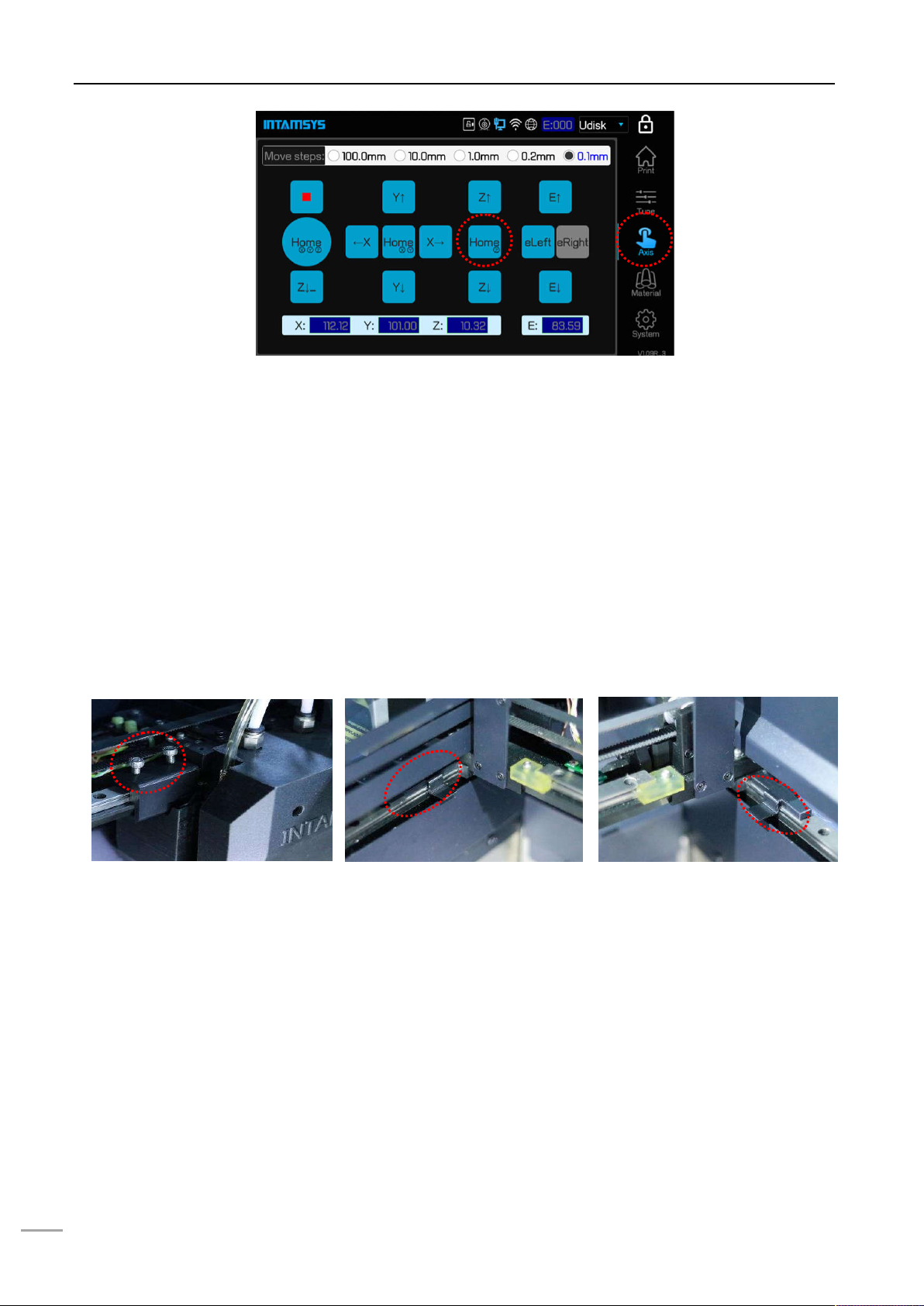
2.2.3 Release the fixation of XY axis
Step 1: Press the round start button on the right of the panel to shut down the printer. Gently pull the right
side of the front door, open the printer's front door, and then open the top door upwards;
Step 2: The fixed block on X axis guideway is used for ensuring the steadiness of the nozzle device
during transportation. Unscrew the two bolts on the fixed block with a 4mmsocket head wrench
(the socket head wrench is placed in the accessory box box) to take off the X axis fixed block;
Step 3: On the linear guideway on the left side, upwards drag the buckle to take out the Y axis left fixed
block;
Step 4: In power-off state, gently push the printing head towards the left on X axis direction to leave
sufficient operating space, and take out the Y axis right fixed block by same method.
Figure 2.6 Positions of fixed blocks on XY axis
2.2.4 Add liquid coolant
Step 1: Remove the charge coverplate on the back of the machine with 2mm socket head wrench (the
2mm socket head wrench is placed in the accessorybox).
Step 2: It can be seen that one end of the charge pipe is fixed on a support by the buckle. Press the
buckle to pull out one end of the liquid adding pipe.
Step 3: Unscrew the screw cap of charge pipe and insert funnel (the funnel is in the spare accessory box).
There is a scale observation window on the left side of the charging inlet. Inject 750~950ml of
liquid coolant via the funnel (it is suggested to add water-free liquid coolant for automobile engine
to reduce the erosion and the generation of incrustation, and colored liquid coolant is
1
2

2 SETUP AND Installation
9
recommended for easier observation).
Step 4: After charging, screw down the screw cap of charge pipe, put the charge pipe back and install the
coverplate.
Figure 2.7 Position of charging inlet and method to charge
2.2.5 Install the printing buildplate
Step 1: In the "Axis" interface, click the key "Home XYZ".
Step 2: Select the option "100mm" in the "Move steps" above, then click "Z↓" (no more than 3 times) and
adjust the printing buildplate to a position convenient for the installation of printing buildplate.
Step 3: Install the printing buildplate according to the direction as shown on the label on printing buildplate,
make the four magnet blocks on the glass be placed into the corresponding magnet holes, and
gently press the four magnet blocks with hand to confirm the magnet blocks are fully placed in the
magnet holes.
Figure 2.8Buildplate descending method
1
2
3

2 SETUP AND INSTALLATION
10
Figure 2.9Buildplate glass installation direction

3 SYSTEM COMPONENTS
11
3 System Components
The system components of FUNMATPRO 410 are described in this chapter, to help users better
understanding the composition principle of the printer, and knowing about the functions of each part.
3.1 Overview of the Printer
The visible parts of the printer from appearance are shown as following figure. Among them, the right
lateral plate, left lateral plate, and back lateral plate are all dismountable, which are used for the
maintenance of internal components; the top door and front door shall be in closed state and be locked by
electromagnetic lock in the process of printing; the material chamber can been seen by opening the lower
door, which is opened by "pushing and bouncing".
Figure 3.1 Front view of the printer
Top door
Switch Button
Right lateral plate
Printing chamber
Lowerdoor/ Material
chamber
Touch screen
user interface
Front door /
Printing
observation window

3 SYSTEM COMPONENTS
12
Figure 3.2 Rear view of the printer
3.2 Top Door Subassembly
By pushing up the top door, the printing state can be observed, and it is also convenient for the
maintenance of XY rack and printing head component.
Release the electromagnetic lock to push up the top door, where the top door is supported by air spring.
Where the opening angle is greater than the critical angle, the support moment of air spring will be greater
than the gravity moment of the top door, which can keep the top door in its opening position. Where the
opening angle of the top door is less than the critical angle, the air spring does not have sufficient support
moment yet, and the top door will fall down freely. Therefore, when opening the top door, please note to
not release your hand when the door opening angle is less than the critical angle, and release hand when
you feel the top door is supported by sufficient force from the air spring.
The user interaction area is under the top door, including the touch screen, USB interface, button switch.
Users can control the printed piece and obtain the information about machine state through the touch
screen. The USB on the left side is onlyused for printingviacomputer.
The USB on the right side is used for printing by plugging in USB flash disk. The button switch is used for
normal switching on and off, and emergency shutdown.
Caster
Mounting screw
Left lateral plate
Back lateral plate
Power interface / Switch
Liquid observation
window

3 SYSTEM COMPONENTS
13
Figure 3.3 Diagram for top door
opening angle
Figure 3.4 Diagram for user operating Area
3.3 Printing Chamber Subassembly
The front door can be pulled out from the right side through releasing the electromagnetic lock by screen
operation, and then it can be seen that following components are included in the printing chamber: front
door, hot bed, dual nozzle component, brass wire brush, electromagnetic lock, magnet, door sensor,
heating and heat maintaining component, etc.
When the printing chamber is heating, please do not touch the stainless steel bottom plate and lateral
plates to avoid scald as they are in high temperature.
The four leveling rotary knobs under the hot bed are used for the manual leveling of the printing
buildplate.
Figure 3.5 Diagram for front door
opening mode
Figure 3.6 Printing chamber
3.4 Material Chamber Subassembly
The material chamber contains two material rolls on the right and left, of which normally model materials
are installed on left material roll and the support materials are installed on the right material roll. There is
Pull
here to
open
the door
Leveling knob
Build plate
Electromagnetic
lock
Magnet
Dual nozzle
Brush
Door sensor
ON/OFF
switch
Air spring
USB-Disk
For USB
printing via PC

3 SYSTEM COMPONENTS
14
weight sensor on each material roll. An alarm will be given on the screen when the weight of materials
arelower than the materials required by printing. There is heating device in the material chamber, which
can be used for auxiliary drying of material chamber, and the maximum temperature of material chamber
can reach up to 70°C. To ensure the dryness of materials, the slide door of material chamber shall be kept
in closed state all the time. The sliding door are held closed by magnetic force when it is in closed state.
To replace materials or do troubleshooting, the sliding door can be opened by pushing it forward slightly,
and the light will be enabled automatically with the opening of chamber.
Figure 3.7 Material chamber
3.5 Printing Head Subassembly
The printing head subassembly is used for fusing wire, and forming the required model on the printing
glass plate in combination with the movement of XYZ axis. The subassembly contains two nozzles, of
which the left nozzle is used to print model material and the right nozzle is used to print support material in
normal cases. The left and right nozzle can be switched by the up and down movement of the right nozzle,
and only one nozzle will execute the printing at one time.
There is also feeding state monitoring sensors (each one on the left and right respectively) on the printing
head subassembly, which will alarm for abnormal material feeding. Refer to Chapter 5 for the loading and
unloading of materials.
Door of material Chamber
Sliding door
Auxiliary feeding
Filament existing sensor
Filament roll
Door sensor
Weight sensor
Light
Other manuals for Funmat Pro 410
2
Table of contents
Other Intamsys 3D Printer manuals

Intamsys
Intamsys FUNMAT HT User manual

Intamsys
Intamsys FUNMAT HT User manual

Intamsys
Intamsys FUNMAT PRO 310 User manual

Intamsys
Intamsys FUNMAT HT User manual

Intamsys
Intamsys FUNMAT PRO User manual

Intamsys
Intamsys FUNMAT PRO User manual

Intamsys
Intamsys FUNMAT PRO 310 User manual

Intamsys
Intamsys Funmat Pro 410 User manual

Intamsys
Intamsys Funmat Pro 410 User manual


