de Gier I-DE User manual

Let’s Gear Up!
User manual
I-DE
–

Figure 1 - I-DE
Content
Inhoud
Inhoud 2
Quickstart 3
Inleiding en overzicht 4
Inleiding 4
Overzicht 4
2 Aansluitschema’s5
2.1 Voeding 5
2.2 Reset ingang 5
2 Aansluitschema’s 6
2.3 Stroomuitgang 6
2.4 A/B/Z uitgangen 6
3 Het gebruik 7
3.1 Knipperpatronen led 7
3 Het gebruik 8
3 Het gebruik 9
3.2 Stroomdiagram I-DE 9
3.3.1 Stroomuitgang 9
3.3.2 A/B/Z uitgangen 9
3 Het gebruik 10
3.4 Foutmode10
3.5 Instelmode 10
3 Het gebruik 11
3.5.1 Positie I-DE resetten (Hoofdmenu 1)11
I-DE installation example
The I-DE is equipped as standard with a thick O-ring, which ensures that it is properly secured in
the motor gearbox housing. In some cases, however, when the wall of the housing is particularly
thick, the safety catch on the I-DE may prove dicult to clip into position. In such instances, the thin
O-ring provided may be used in place of the thick O-ring.

De Gier B.V., Westlandseweg 9, 2291 PG WATERINGEN, THE NETHERLANDS,
Versie 1 – 07/01/2021
4
226
M10 (4x)
90
Stc.
105
69
104
L
110
15
245
60 43
38 30
100
M10 (4x)
15
60
120
50 59 44
292
13
4
M10 (4x)
226
82
171
L
176
90
M10 (4x)
Stc. Ø105
12
56 46 60
292
54
21
100
6
M10 (4x)
123
226
74
132
L
13
Stc.
105
M10 (4x)
90
GW10
GW20 - GW30
GW40 - GW150
Quickstart
Step Action Aim
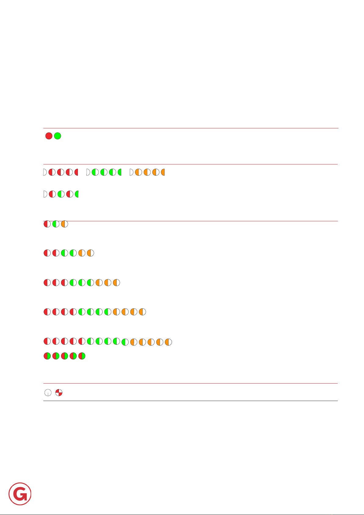
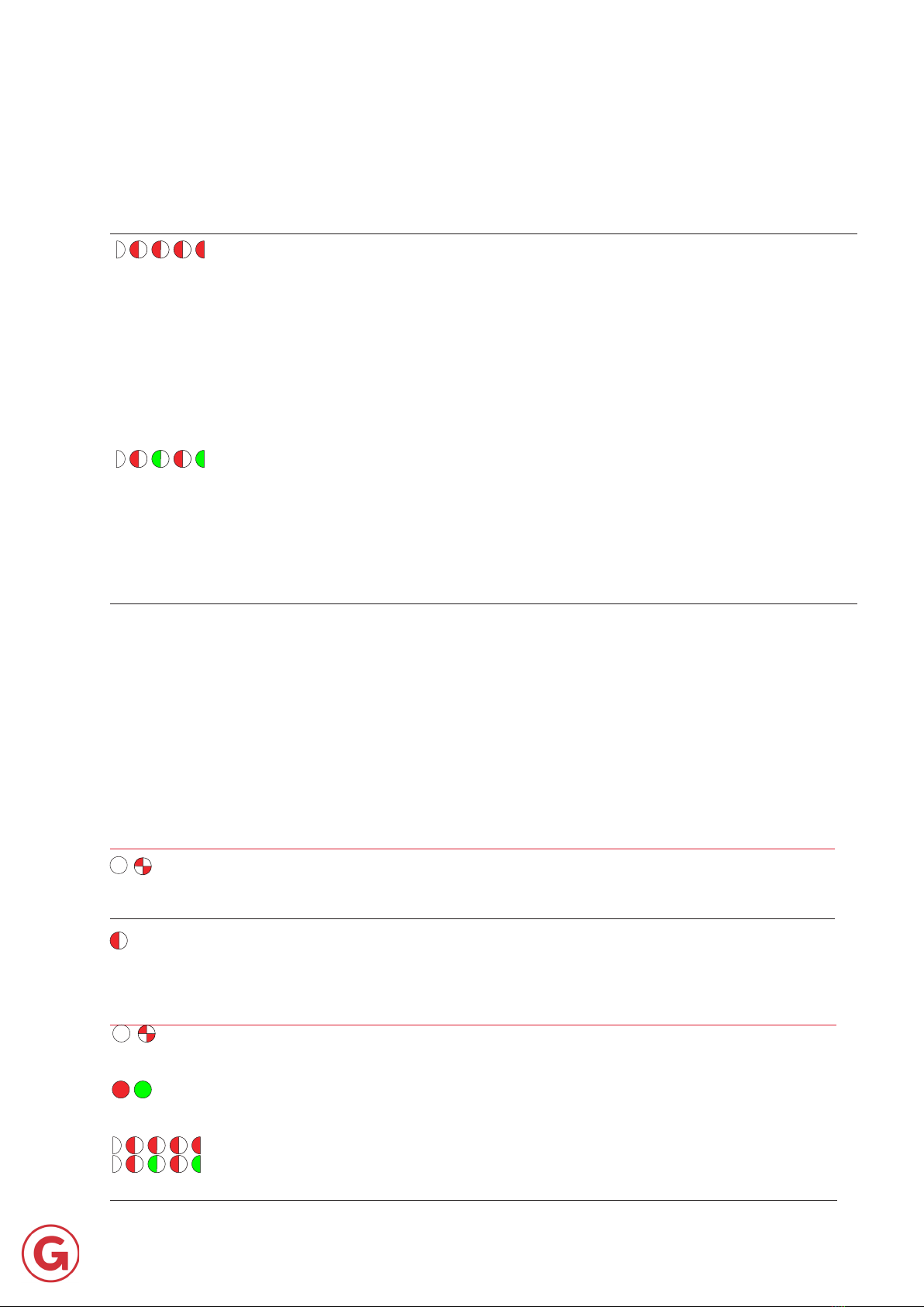
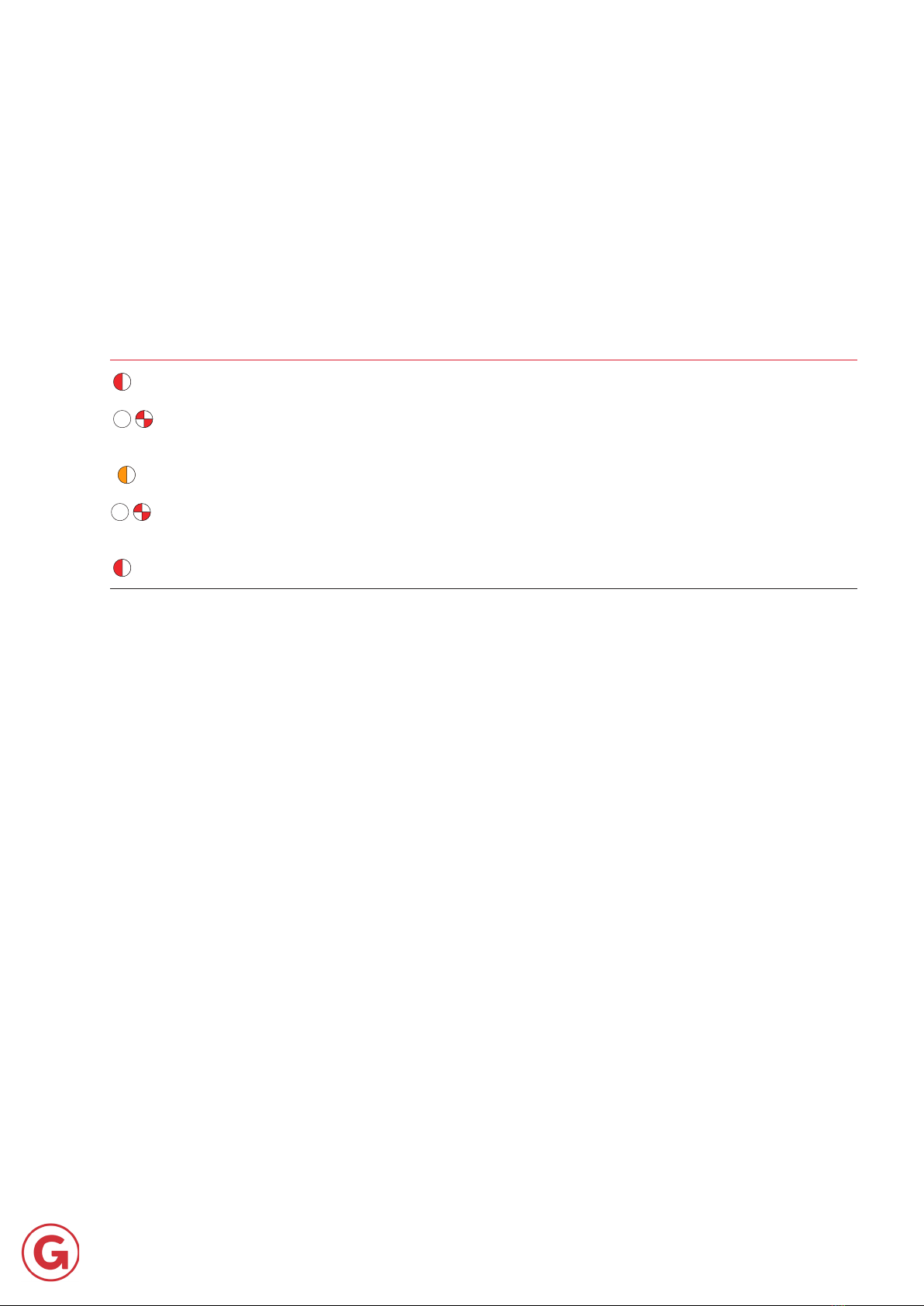
LED colour/pattern
during action
LED colour/
pattern
after action
Symbol Description of LED on the I-DE

5
De Gier B.V., Westlandseweg 9, 2291 PG WATERINGEN, THE NETHERLANDS,
Versie 1 – 07/01/2021
Figur 2 - Overview of I-DE
Introduction and summary
Introduction
Summary
BUTTON

De Gier B.V., Westlandseweg 9, 2291 PG WATERINGEN, THE NETHERLANDS,
Versie 1 – 07/01/2021
6
2.2 Reset input
Note!
2 Wiring Diagram
2.1 Power supply

7
De Gier B.V., Westlandseweg 9, 2291 PG WATERINGEN, THE NETHERLANDS,
Versie 1 – 07/01/2021
2.3 Current ouput
2.4 A/B/Z outputs
2 Wiring Diagram
8
De Gier B.V., Westlandseweg 9, 2291 PG WATERINGEN, THE NETHERLANDS,
Versie 1 – 07/01/2021
3 Operation
Normal operation
Error mode
Calibration mode
Conrming a selection

De Gier B.V., Westlandseweg 9, 2291 PG WATERINGEN, THE NETHERLANDS,
Versie 1 – 07/01/2021
9
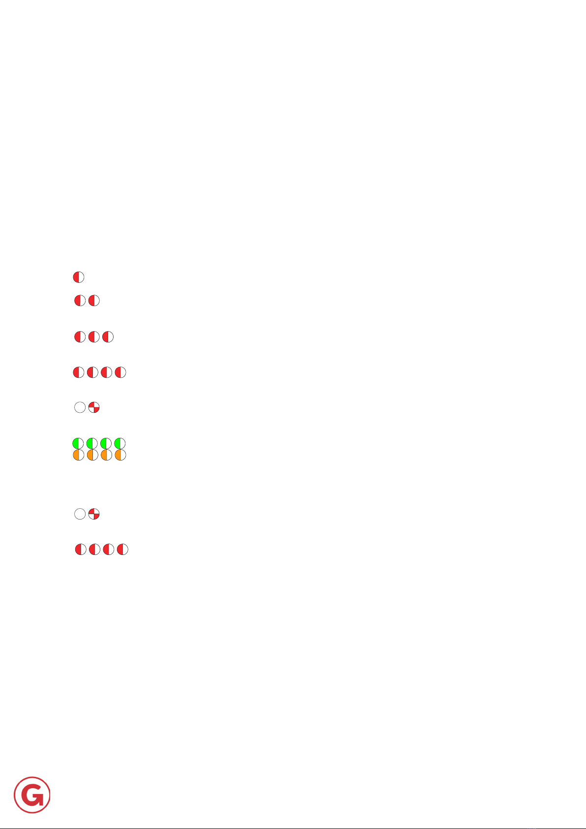
3 Operation
Seconds
in diagram
Hold down
push button LED Step
= =
= =
= =
= =
Figure 7 - I-DE ow diagram

De Gier B.V., Westlandseweg 9, 2291 PG WATERINGEN, THE NETHERLANDS,
Versie 1 – 07/01/2021
10
3 Operation
Seconds
in diagram
Hold down
push button LED Step
= =
= =
= =
= =
Figure 7 - I-DE ow diagram

11
De Gier B.V., Westlandseweg 9, 2291 PG WATERINGEN, THE NETHERLANDS,
Versie 1 – 07/01/2021
Figure 9 - Explanation of A/B/Z/ signals
3 Operation
3.2 I-DE ow diagram
Figure 7
NOTE!
"two second action"
Situations during normal operation
not
3.3.1 Output current
3.3.2 A/B/Z out-
puts
12
De Gier B.V., Westlandseweg 9, 2291 PG WATERINGEN, THE NETHERLANDS,
Versie 1 – 07/01/2021
3 Operation
3.4 Error mode
Situations in Error mode
3.5 Calibration mode
Access the main menu
Exit the main menu
13
De Gier B.V., Westlandseweg 9, 2291 PG WATERINGEN, THE NETHERLANDS,
Versie 1 – 07/01/2021
3 Operation
3.5.1 Reset I-DE position (Main menu 1)
NOTE«main menu 1»Figure 7
«Normal operation»«Error mode»«Main menu 1»
Reset I-DE position

De Gier B.V., Westlandseweg 9, 2291 PG WATERINGEN, THE NETHERLANDS,
Versie 1 – 07/01/2021
14
3.5.2 Calibrate I-DE (Main menu 2)
3 Operation
Calibrate I-DE

15
De Gier B.V., Westlandseweg 9, 2291 PG WATERINGEN, THE NETHERLANDS,
Versie 1 – 07/01/2021
3.5.3 Adjusting the I-DE current range (Main menu 3)
Figure 7
3 Operation
Calibrate I-DE
Adjust I-DE current range
16
De Gier B.V., Westlandseweg 9, 2291 PG WATERINGEN, THE NETHERLANDS,
Versie 1 – 07/01/2021
3.5.4 Set I-DE current output start position (Main menu 4)
3 Operation

17
De Gier B.V., Westlandseweg 9, 2291 PG WATERINGEN, THE NETHERLANDS,
Versie 1 – 07/01/2021
3.5.4 Set I-DE current output start position (Main menu 4)
3 Operation
3.5.5 I-DE A/B/Z mode conguration (Main menu 5)
NOTE: Improper use of this function may cause damage to
external equipment
18
De Gier B.V., Westlandseweg 9, 2291 PG WATERINGEN, THE NETHERLANDS,
Versie 1 – 07/01/2021
4 Technical Specications
3.6 Power failure
3.7 Limit switch and reset position
3.8 Restoring the factory settings
4. Technical Specications

De Gier B.V., Westlandseweg 9, 2291 PG WATERINGEN, THE NETHERLANDS,
Versie 1 – 07/01/2021
19
3.5.2 Calibrate I-DE (Main menu 2)
3 Operation
Calibrate I-DE

20
De Gier B.V., Westlandseweg 9, 2291 PG WATERINGEN, THE NETHERLANDS,
Versie 1 – 07/01/2021
3.5.3 Adjusting the I-DE current range (Main menu 3)
Figure 7
3 Operation
Adjust I-DE current range
Table of contents


