Wachendorff WDGA Series User manual

-
-
-
-
-
-
-
-
-
-
-
-
-
-
-
-
-
-
-
-
-
-
-
-
-
-
-
-
-
-
-
-
-
-
-
-
-
-
-
-
-
-
-
-
-
-
-
-
-
R
e
v

Technical Manual
WDGA with EtherCAT
© Wachendorff Automation GmbH & Co. KG
I
Rev.1.09
Legal information
Wachendorff Automation GmbH & Co. KG
Industriestrasse 7
65366 Geisenheim
Germany
Tel: +49 (0) 67 22 / 99 65 25
Fax: +49 (0) 67 22 / 99 65 70
E-mail: [email protected]
Website: www.wachendorff-automation.de
Wiesbaden District Court HRA 8377, VAT ID No: DE 814567094
Managing Director: Robert Wachendorff
Warranty waiver, right of amendment, copyright:
Wachendorff Automation accepts no liability or warranty for the correctness of this
manual, or for any direct or indirect damage that may arise from it. In the pursuit of
constant innovation and cooperation with customers, we reserve the right to amend
technical data or content at any time.
Wachendorff Automation asserts copyright over this manual. It may not be modified,
added to, reproduced or shared with third parties without prior written consent.
EtherCAT® is a registered trademark and patented technology, licensed by Beckhoff
Automation GmbH, Germany.
Comments:
Should you have any corrections, notes or requests for changes, please send them to
us. Send your comments to: wdg@wachendorff.de

Technical Manual
WDGA with EtherCAT
Table of contents
© Wachendorff Automation GmbH & Co. KG
II
Rev.1.09
1Introduction .....................................................................................1
1.1 About this manual.......................................................................................... 1
1.1.1 Explanation of symbols........................................................................... 2
1.1.2 What you will not find in this manual....................................................... 2
1.2 Product assignment....................................................................................... 3
1.3 Description of services .................................................................................. 3
1.4Supplied package.......................................................................................... 4
2Safety information...........................................................................5
2.1 General.......................................................................................................... 5
2.2 Correct use.................................................................................................... 5
2.3 Safe working.................................................................................................. 6
2.4 Disposal......................................................................................................... 6
3Description of the equipment.........................................................7
3.1 General.......................................................................................................... 7
3.2 EtherCAT....................................................................................................... 7
3.3 Principles of WDGA....................................................................................... 8
3.3.1 Single-turn - ST (QuattroMag®).............................................................. 9
3.3.2 Multi-turn - MT (EnDra®) ........................................................................ 9
3.3.3 Direction of revolution ............................................................................. 9
3.3.4 Preset ..................................................................................................... 9
3.3.5 Scaling.................................................................................................... 9
3.4 Things to consider when connecting EtherCAT encoders........................... 11
3.4.1 BI2 - bus cover with 3 x M12x1............................................................. 11
3.5 LEDs and signalling..................................................................................... 12
3.6 MAC address and IP address...................................................................... 14
4EtherCAT........................................................................................15
4.1 Summary of functions.................................................................................. 15
4.2 Communication protocols............................................................................ 15
4.3 CAN over EtherCAT (CoE).......................................................................... 15
4.3.1 General................................................................................................. 15
4.3.2 Communication-specific objects............................................................ 16
4.3.2.1 1000h –Device type....................................................................... 19
4.3.2.2 1001h –Error register..................................................................... 19
4.3.2.3 1008h –Manufacturer device name............................................... 20

Technical Manual
WDGA with EtherCAT
Table of contents
© Wachendorff Automation GmbH & Co. KG
III
Rev.1.09
4.3.2.4 1010h –Store parameters.............................................................. 20
4.3.2.5 1011h –Restore parameters.......................................................... 20
4.3.2.6 1018h - Identity object.................................................................... 21
4.3.2.7 10F3h –Diagnosis history.............................................................. 21
4.3.2.8 1A00h –1st TPDO mapping parameter ......................................... 21
4.3.2.9 1A01h –2nd TPDO mapping parameter........................................ 22
4.3.2.10 1C00h –Sync Manager communication type................................ 23
4.3.2.11 1C13h –Sync Manager 3 PDO assignment.................................. 23
4.3.2.12 1C33h –Sync Manager 3 synchronisation.................................... 24
4.3.3 Manufacturer-specific objects ............................................................... 25
4.3.3.1 2105h –Integration values............................................................. 26
4.3.3.2 2107h –Frequency limit................................................................. 26
4.3.3.3 2120h –Customer flash area......................................................... 26
4.3.3.4 2900h –IP address ........................................................................ 26
4.3.3.5 2901h –Subnet mask..................................................................... 26
4.3.3.6 2902h –Gateway ........................................................................... 26
4.3.4 Encoder-specific objects....................................................................... 27
4.3.4.1 6000h –Operating parameters....................................................... 34
4.3.4.2 6001h –Measuring units per revolution.......................................... 34
4.3.4.3 6002h –Total measuring range...................................................... 34
4.3.4.4 6003h –Preset value...................................................................... 35
4.3.4.5 6004h –Position value................................................................... 35
4.3.4.6 6008h –High-precision position value............................................ 35
4.3.4.7 6009h –High-precision preset value.............................................. 35
4.3.4.8 600Ah –High-resolution total measuring range ............................. 35
4.3.4.9 600Bh –High-resolution position raw value ................................... 35
4.3.4.10 600Ch –Position raw value........................................................... 35
4.3.4.11 6030h –Speed value..................................................................... 35
4.3.4.12 6031h –Speed parameters........................................................... 36
4.3.4.13 6300h –CAM state register........................................................... 36
4.3.4.14 6301h –CAM enable register........................................................ 37
4.3.4.15 6302h –CAM polarity register ....................................................... 37
4.3.4.16 6310h … 6317h – CAM1…CAM8 low limit .................................... 38
4.3.4.17 6320h … 6327h – CAM1…CAM8 high limit................................... 38
4.3.4.18 6330h … 6337h – CAM1…CAM8 hysteresis................................. 38
4.3.4.19 6340h … 6347h – High-resolution CAM1…CAM8 low limit ........... 38

Technical Manual
WDGA with EtherCAT
Table of contents
© Wachendorff Automation GmbH & Co. KG
IV
Rev.1.09
4.3.4.20 6350h … 6357h – High-resolution CAM1…CAM8 high limit.......... 38
4.3.4.21 6360h … 6367h – High-resolution CAM1…CAM8 hysteresis........ 38
4.3.4.22 6400h –Work area state register................................................... 39
4.3.4.23 6401h - Work area low limit ........................................................... 39
4.3.4.24 6402h –Work area high limit......................................................... 39
4.3.4.25 6410h –High-resolution area state register................................... 39
4.3.4.26 6411h –High-resolution work area low limit .................................. 39
4.3.4.27 6412h –High-resolution work area high limit................................. 39
4.3.4.28 6500h –Operating status .............................................................. 39
4.3.4.29 6501h –Single-turn resolution....................................................... 40
4.3.4.30 6502h –Number of distinguishable revolutions............................. 40
4.3.4.31 6503h –Alarms.............................................................................. 40
4.3.4.32 6504h –Supported alarms ............................................................ 40
4.3.4.33 6505h –Warnings.......................................................................... 41
4.3.4.34 6506h –Supported warnings......................................................... 41
4.3.4.35 6507h –Profile and software version............................................. 41
4.3.4.36 6508h –Operating time................................................................. 42
4.3.4.37 6509h –Offset value...................................................................... 42
4.3.4.38 650Ah –Module identification........................................................ 42
4.3.4.39 650Bh –Serial number.................................................................. 42
4.3.4.40 650Dh –Absolute accuracy........................................................... 42
4.3.4.41 650Eh –Device capability ............................................................. 42
4.3.4.42 650Fh –Offset value for high-resolution encoder.......................... 42
4.3.4.43 6510h –Number of high-precision revolutions .............................. 43
5Web server (CAUTION)..................................................................44
5.1 General........................................................................................................ 44
5.2 Information .................................................................................................. 45
5.2.1 Summary............................................................................................... 45
5.2.2 Diagnosis.............................................................................................. 46
5.2.3 Versions................................................................................................ 47
5.3 Configuration............................................................................................... 48
5.3.1 Network................................................................................................. 48
5.3.2 Encoder................................................................................................. 49
5.3.3 Firmware update................................................................................... 50
5.4 Licence information ..................................................................................... 53

Technical Manual
WDGA with EtherCAT
Table of contents
© Wachendorff Automation GmbH & Co. KG
V
Rev.1.09
5.5 Contact........................................................................................................ 53
6Commissioning with TwinCAT .....................................................54
7Technical advice............................................................................61

Technical Manual
WDGA with EtherCAT
Index of illustrations
© Wachendorff Automation GmbH & Co. KG
VI
Rev.1.09
Index of illustrations
Figure 3.1: WDGA with EtherCAT bus cover.............................................................. 7
Figure 5.1: Web server –Summary.......................................................................... 45
Figure 5.2: Diagnostics page.................................................................................... 46
Figure 5.3: Versions ................................................................................................. 47
Figure 5.4: Network settings..................................................................................... 48
Figure 5.5: Encoder information ............................................................................... 49
Figure 5.6: Firmware update..................................................................................... 50
Figure 5.7: Firmware update - selecting the file........................................................ 50
Figure 5.8: Firmware update - transfer file................................................................ 51
Figure 5.9: Firmware update - successful................................................................. 52
Figure 5.10: Firmware update - failed....................................................................... 52
Figure 5.11: Licence information .............................................................................. 53
Figure 5.12: Contact information .............................................................................. 53
Figure 6.1: TwinCAT –Scan..................................................................................... 54
Figure 6.2: TwinCAT - Scan / Message.................................................................... 55
Figure 6.3: TwinCAT - IO devices............................................................................. 55
Figure 6.4: TwinCAT –Scan for boxes..................................................................... 56
Figure 6.5: TwinCAT - Scan complete...................................................................... 56

Technical Manual
WDGA with EtherCAT
Index of tables
© Wachendorff Automation GmbH & Co. KG
VII
Rev.1.09
Index of tables
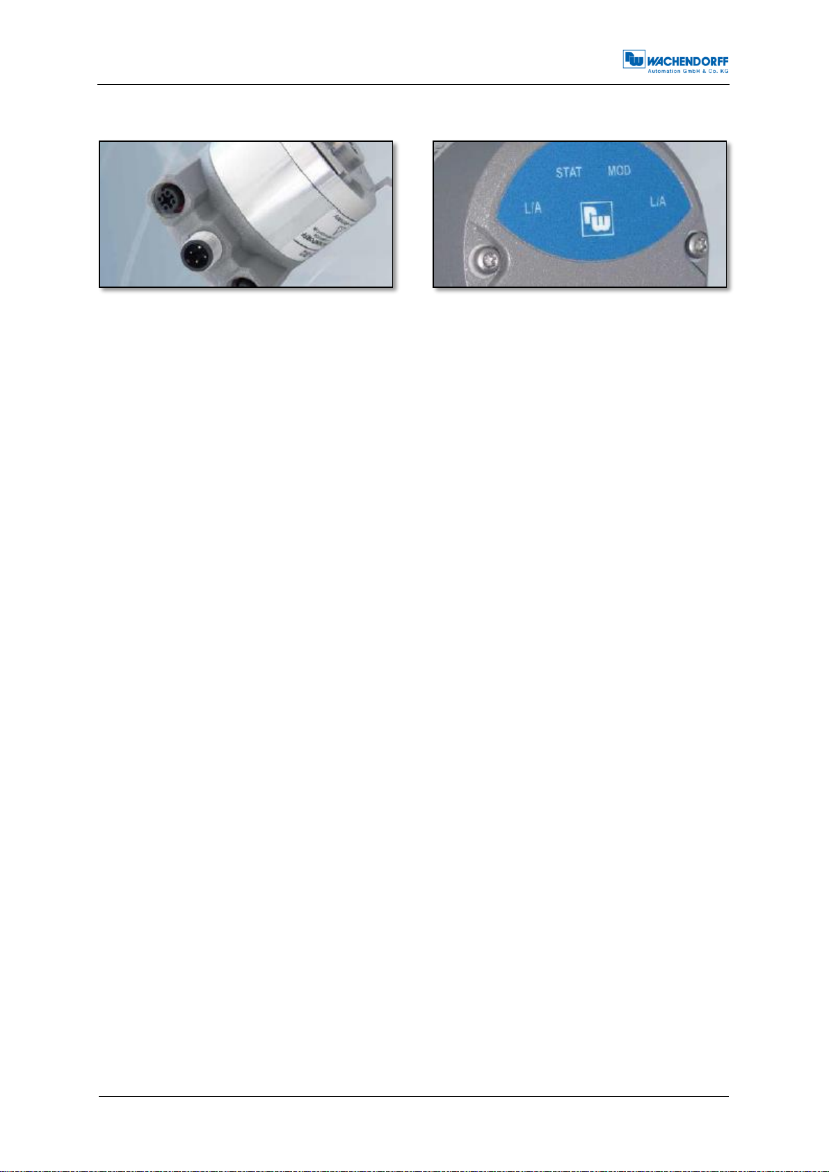
Table 3.1: Pin assignment........................................................................................ 11
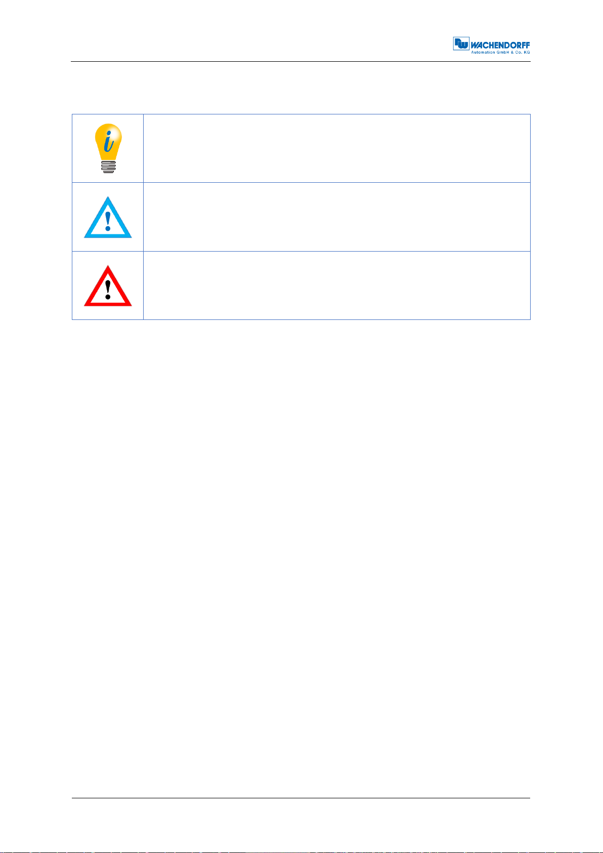
Table 3.2: LED signals.............................................................................................. 13
Table 4.1: Summary of the encoder's functions........................................................ 15
Table 4.2: Communication protocols........................................................................ 15
Table 4.3: Object directory 1000h - 1018h................................................................ 16
Table 4.4: Object directory 10F3h - 1A00h............................................................... 17
Table 4.5: Object directory 1A01h - 1C00h............................................................... 18
Table 4.6: Object directory 1C13h - 1C33h .............................................................. 19
Table 4.6: 1001h –Error register.............................................................................. 19
Table 4.7: 1001h –Parameter storage options......................................................... 20
Table 4.8: 1011h –Parameters loading options....................................................... 20
Table 4.9: 1018h –Identity object............................................................................. 21
Table 4.10: 1010h –Identity object........................................................................... 21
Table 4.11: 1st transmit PDO default mapping (EtherCAT object 1A00h)................ 21
Table 4.12: Setup of sub-index 01 ... 08 of object 1A00h......................................... 22
Table 4.13: 2nd transmit PDO default mapping (EtherCAT object 1A01h)............... 22
Tabelle 4.14: Sync Manager communication type (EtherCAT object 1C00h)........... 23
Tabelle 4.15: Sync Manager 3 PDO assignment (EtherCAT Objekt 1C13).............. 23
Table 4.17: Sync Manager 3 synchronisation (EtherCAT Objekt 1C33h)................. 24
Table 4.16: Manufacturer-specific objects 2105h - 2902h........................................ 25
Table 4.17: Integration values (EtherCAT object 2105h).......................................... 26
Table 4.18: Frequency limit (EtherCAT object 2107h).............................................. 26
Table 4.19: Device-specific objects 6000h - 6031h.................................................. 27
Table 4.20: Device-specific objects 6009h - 6310h.................................................. 28
Table 4.21: Device-specific objects 6311h - 6321h.................................................. 29
Table 4.22: Device-specific objects 6322h - 6332h.................................................. 30
Table 4.23: Device-specific objects 6337h - 6402h.................................................. 31
Table 4.24: Device-specific objects 6410h - 6508h.................................................. 32
Table 4.25: Device-specific objects 6509h - 6510h.................................................. 33
Table 4.26: Direction of revolution and scaling parameters...................................... 34
Table 4.27: Speed selector....................................................................................... 36
Table 4.28: CAM state register - value 89h .............................................................. 36
Table 4.29: CAM state register - value 81h .............................................................. 37
Table 4.30: CAM enable register - value 4Ah........................................................... 37
Table 4.31: Example of the CAM polarity register .................................................... 37
Table 4.32: 6503h - Alarms ...................................................................................... 40
Table 4.33: Signal description .................................................................................. 41
Table 4.34: Example of profile software version....................................................... 41

Technical Manual
WDGA with EtherCAT
1 - Introduction
© Wachendorff Automation GmbH & Co. KG
1
Rev.1.09
1 Introduction
1.1 About this manual
This technical manual describes the configuration and assembly options for absolute
encoders from Wachendorff Automation with an EtherCAT interface. It represents an
addition to the other published Wachendorff Automation documents, such as the
datasheets, assembly instructions, supplements, catalogues and flyers.
Read the manual before using theequipment. Check first that the version of the manual
you have is the most recent.
When reading, pay particular attention to information, important and warning points
that are marked with corresponding symbols (see 1.1.1).
This manual is designed for people with technical knowledge and experience of using
sensors, EtherCAT interfaces and automation elements. If you do not have any
experience of this equipment, please seek assistance from people who do.
Store the information supplied with our product carefully so that you can refer to itagain
at a later date if necessary.
The contents of this manual are arranged with practical use in
mind.
All of the information in the following sections is required to get
the best possible use out of the equipment, and should be read
through thoroughly.

Technical Manual
WDGA with EtherCAT
1 - Introduction
© Wachendorff Automation GmbH & Co. KG
2
Rev.1.09
1.1.1 Explanation of symbols
The INFO symbol is placed next to a section of text that is
particularly informative or important for what to do next with the
equipment.
The IMPORTANT symbol is placed next to a section of text in
which a process is described to resolve a particular problem.
The WARNING symbol is placed next to a section of text that
should be paid particular attention to in order to ensure the
correct use of the equipment and to protect against danger.
1.1.2 What you will not find in this manual
•Principles of automation technology
•System planning
•Risks (availability, safety)
•Shielding concepts
•Reflections
•Repeaters
•Network configuration
•Bus cycle time
•FMA management services
•Transfer services
•Telegram types

Technical Manual
WDGA with EtherCAT
1 - Introduction
© Wachendorff Automation GmbH & Co. KG
3
Rev.1.09
1.2 Product assignment
This manual is assigned to the following types of encoder from Wachendorff
Automation with the article designations below:
Absolute solid shaft encoder:
WDGA 58A EtherCAT (BI2) –(with bus cover)
WDGA 58B EtherCAT (BI2) –(with bus cover)
WDGA 58D EtherCAT (BI2) –(with bus cover)
WDGA 58F EtherCAT (BI2) –(with bus cover)
Absolute end hollow shaft encoder:
WDGA 58E EtherCAT (BI2) –(with bus cover)
The EtherCAT product range from Wachendorff can be found
on our website: www.wachendorff-automation.de
1.3 Description of services
An encoder is a sensor used to capture angle positions (single-turn) and revolutions
(multi-turn). The measuring data and variables derived from this are processed by the
encoder and provided as electrical output signals for the downstream peripherals.
In the WDGA series, the patented technologies QuattroMag® and EnDra® are used
for single-turn and multi-turn encoders respectively. This means that the WDGA series
from Wachendorff is especially maintenance-free and environmentally friendly.
The encoders bearing the article designations described in Section 1.2 communicate
via the EtherCAT interface.

Technical Manual
WDGA with EtherCAT
1 - Introduction
© Wachendorff Automation GmbH & Co. KG
4
Rev.1.09
1.4 Supplied package
The supplied package depends on the type of the design and your order. Before
commissioning, you should check the supplied package for completeness.
Generally speaking, the WDGA product series with an EtherCAT interface comprises
the following supplied package:
WDGA with EtherCAT (with bus cover)
Assembly instructions
The corresponding ESI file and matching datasheet are available
on the Internet to download: www.wachendorff-automation.de

Technical Manual
WDGA with EtherCAT
2 - Safety information
© Wachendorff Automation GmbH & Co. KG
5
Rev.1.09
2 Safety information
2.1 General
The assembly instructions, the manual and the datasheet must
all be read thoroughly before commissioning the encoder.
Failure to comply with the safety information can result in
malfunctions, material damage and physical injury!
The machine manufacturer's operating instructions must be
observed.
2.2 Correct use
Encoders are components designed for installation in machinery. Before
commissioning (correct operation), it must be ensured that the machine as a whole
complies with the EMC and Machinery directives.
The encoder is a sensor for capturing angle positions and revolutions and should only
be used for such purposes! Encoders from Wachendorff Automation are produced and
marketed for industrial use outside the safety/security sector.
The encoder must not be operated outside the specified limit
parameters (see associated datasheet).

Technical Manual
WDGA with EtherCAT
2 - Safety information
© Wachendorff Automation GmbH & Co. KG
6
Rev.1.09
2.3 Safe working
The installation and assembly of the encoder must be carried out exclusively by a
qualified electrician.
National and international regulations applicable to the setup of electrical systems must
be complied with.
If the encoder is not commissioned correctly, malfunctions or failures can occur.
All electrical connections must be checked before
commissioning.
Suitable safety measures should be deployed to ensure that,
in the event of a failure or malfunction, no physical harm can
occur and there is no damage to the system or operating
facilities.
2.4 Disposal
Equipment that is no longer needed or which is faulty must be disposed of correctly by
the user in accordance with country-specific legislation. It must be remembered that
this equipment represents special electronic waste and it must not be disposed of in
normal domestic waste.
The manufacturer is not obliged to take back the equipment. For questions relating to
correct disposal, please contact a professional disposal company near you.

Technical Manual
WDGA with EtherCAT
3 - Description of the equipment
© Wachendorff Automation GmbH & Co. KG
7
Rev.1.09
3 Description of the equipment
3.1 General
There are various mechanical versions of the WDGA series with EtherCAT. Crucial in
this context is the design, with or without bus cover, the nature of the flange and the
type of shaft (full or end hollow shaft). The size is specified by the diameter on the
flange at 58 mm. The illustration below shows examples of the WDGA series with
EtherCAT.
Figure 3.1: WDGA with EtherCAT bus cover
The full or end hollow shaft is linked to the revolving part whose angle position or speed
is to be measured. Cable or plug outlets form the interface to the connection to the
EtherCAT network. The status LEDs in the cover indicate the various states of the
encoder during use. They support the configuration of the encoder or troubleshooting
in the field. The flange drill holes or supplied spring plates are used to secure the
encoder to the machine or while in use.
3.2 EtherCAT
EtherCAT is a real-time Ethernet technology that was originally discovered by Beckhoff
Automation. The EtherCAT protocol published in the IEC standard IEC 61158 is
suitable for hard as well as soft real-time requirements in automation technology, in
measuring technology and in a number of other applications.
EtherCAT was unveiled in April 2003 and the EtherCAT Technology Group (ETG) was
founded in November 2003. Meantime, the ETG has grown to become the largest
industrial Ethernet and field bus user organisation in the world. The ETG brings
manufacturers and users together who contribute to the technology's development in
technical working groups.

Technical Manual
WDGA with EtherCAT
3 - Description of the equipment
© Wachendorff Automation GmbH & Co. KG
8
Rev.1.09
The focal areas of EtherCAT's development were short cycle times (≤ 100 µs), low jitter
for precise synchronisation (≤ 1 µs) and low hardware costs.
The telegram sent by the EtherCAT master runs through all network members. Every
EtherCAT slave reads the output data addressed to it and places its input data in the
forwarded data frame while the telegram is passing through the device. The telegram
is only delayed by hardware cycle times. The last member in a segment (or branch)
detects an open port and sends the telegram back to the master. The full duplex
capability of Ethernet is used for this.
The maximum user data rate of a telegram is over 90%, while the theoretical effective
data rate from the use of the full duplex capability is in excess of 100 Mbit/s (> 90% of
two x 100 Mbit/s).
The EtherCAT master is the only member in the segment that can actively send an
EtherCAT frame; all other members simply pass the frames on. This avoids
unexpected delays and guarantees real-time compatibility.
The master uses a standard Ethernet medium access controller (MAC) without an
additional communication processor. This means that a master can be installed on any
hardware platform that provides an Ethernet port. The EtherCAT slaves use an
EtherCAT slave controller (ESC) for processing in the cycle that is handled entirely in
hardware. This means that network performance can be predicted and is independent
of the individual slave device implementation. [EtherCAT Technology Group,
www.ethercat.org, 2017]
Further information on EtherCAT can be found on the EtherCAT Technology Group's
website at:
https://www.ethercat.org
3.3 Principles of WDGA
The sections below describe the basic functions on absolute encoder.
Unlike incremental encoders, absolute encoders output their position value as a digital
number via a field bus. A distinction is made between single-turn and multi-turn
encoders.
In addition to the simple outputof the position value, most encoders also allowa certain
degree of parametrisation, such as the choice of positive direction of revolution, the
setting of the position value to a reference value at a defined physical position and
scaling of the position value to a desired resolution and a limited measuring range. As
a result, the amount of development work required in the control program is reduced,
and the computing capacity of the control unit is relieved.

Technical Manual
WDGA with EtherCAT
3 - Description of the equipment
© Wachendorff Automation GmbH & Co. KG
9
Rev.1.09
3.3.1 Single-turn - ST (QuattroMag®)
The measurement of the angle from 0° to 360° using a shaft is an encoder’s simplest
function. The sensors are based on the optical or magnetic scanning of a material
measure on the encoder shaft.
The WDGA encoders from Wachendorff use the new magnetic QuattroMag®
technology that ensures maximum accuracy and resolution of the single turn.
3.3.2 Multi-turn - MT (EnDra®)
A multi-turn encoder allows the number of revolutions to be recorded. This is carried
out using a revolution counter. To ensure that the relevant information is retained even
when the voltage is switched off, WDGA encoders use EnDra® technology. Buffer
batteries and drives that require a relatively large amount of spaceand a corresponding
amount of maintenance can therefore be replaced.
3.3.3 Direction of revolution
A simple two-part complement (invert each bit and add "1") of the position value can
reverse the positive direction of revolution.
3.3.4 Preset
In a specific physical position, the encoder can be assigned a desired position value.
This must be within the measuring range so that the position value correlates to a
physical reference position. To do this, the difference between the current position
value and the desired value is calculated. This is stored in a non-volatile memory and
added to the position value as an offset.
3.3.5 Scaling
For the precise matching of the position value with the parameter to be measured in
physical terms, adaptation can be carried out using the scaling parameters. The
scalable parameters are "Measuring units per revolution (MUPR)" and "Total
measuring range in measuring units (TMR)".
The scaling parameters "Measuring units per revolution (MUPR)" - increments per
revolution - specify the resolution of the position value for each revolution (also:
ST -resolution). The value equates to 360°. This means that, if a value of 3600 Cts is
parametrised, the encoder outputs the position in 0.1° increments (see equation (2)).

Technical Manual
WDGA with EtherCAT
3 - Description of the equipment
© Wachendorff Automation GmbH & Co. KG
10
Rev.1.09
𝑀𝑈𝑃𝑅 = 𝑆𝑇 =3600 𝐶𝑡𝑠
(1)
𝑎𝑛𝑔𝑢𝑙𝑎𝑟 𝑠𝑡𝑒𝑝𝑠 = 𝑎𝑛𝑔𝑙𝑒 𝑜𝑓 𝑜𝑛𝑒 𝑟𝑒𝑣𝑜𝑙𝑢𝑡𝑖𝑜𝑛
𝑀𝑈𝑃𝑅 =360°
3600 𝐶𝑡𝑠 = 0,1°/𝐶𝑡𝑠
(2)
The scaling parameter "Total measuring range in measuring units (TMR)" - maximum
overall measuring range of the position value (single-turn and multi-turn multiplied) -
indicates the encoder's overall resolution. Once the position value reaches TMR - 1, it
skips back to 0 and vice versa.
Generally speaking, the TMR parameter is chosen so that it is a whole integer multiple
of the "Measuring units per revolution (MUPR)" (see equation (4)), so that the zero
point is always located at the same position on the encoder shaft.
𝑇𝑀𝑅 = 36000 𝐶𝑡𝑠
(3)
𝑀𝑇 =𝑇𝑀𝑅
𝑀𝑈𝑃𝑅 =36000 𝐶𝑡𝑠
3600 𝐶𝑡𝑠 =10
(4)
In exceptional cases, the TMR does not need to be a whole integer multiple of the
MUPR. For example if a translation in a system causes the desired measuring
parameter to move 10% faster in relation to the encoder shaft than the encoder shaft
itself.
In this case, the setting of MUPR = 3960 Cts and TMR = 36000 Cts would ensure that
the faster, but not directly measurable, shaft can be measured with a resolution of 0.1°
and over a range of 10 revolutions. Normally, it would be possible to calculate the
revolution speed by dividing the position value by the MUPR. In this case, however, it
must be divided by 3600 Cts since the result would otherwise be the revolution speed
of the encoder shaft and not the speed of the faster shaft in the system.
It should be noted that measuring errors occur if the result of
this formula is a decimal.

Technical Manual
WDGA with EtherCAT
3 - Description of the equipment
© Wachendorff Automation GmbH & Co. KG
11
Rev.1.09
3.4 Things to consider when connecting EtherCAT encoders
3.4.1 BI2 - bus cover with 3 x M12x1
The "BI2" code in the order key refers to an encoder with a bus cover. The electrical
connection is made at the bus cover via the 2 x M12 plugs and 1 x M12 socket. The
connection assignment of the plugs and sockets can be found in Table 3.1.
Connection
assignment
BI2
Socket
(Port 1)
IN
M12x1,
4-pin,
D-coded
Tx+
1
Rx+
2
Tx-
3
Rx-
4
Connection
assignment
BI2
Plug
(Power)
M12x1,
4-pin,
A-coded
UB+
1
n. c.
2
UB-
3
n. c.
4
Connection
assignment
BI2
Socket
(Port 2)
OUT
M12x1,
4-pin,
D-coded
Tx+
1
Rx+
2
Tx-
3
Rx-
4
Table 3.1: Pin assignment

Technical Manual
WDGA with EtherCAT
3 - Description of the equipment
© Wachendorff Automation GmbH & Co. KG
12
Rev.1.09
3.5 LEDs and signalling
Four status LEDs in the cover indicate the various states of the encoder and support
diagnosis and troubleshooting in the field (see Table 3.2). The two Link Activity LEDs
(L/A) light up or flash green if the encoder is connected to another EtherCAT node
(SPS, switch, other field device, etc.) and data is being exchanged. The MOD LED
indicates operation, always lighting up green when the supply voltage is connected.
The STAT LED indicates the EtherCAT status. Red signals in the STAT LED indicate
errors, while green ones indicate the bus status. The green signals are always
displayed in the pause between the red signals. This means that, in the event of
uncertainty, the red signals take priority.
Run flashing signals:
Flashing
2.5 Hz
0
100
200
300
400
500
C
y
c
l
e
Flickering
10 Hz
0
50
100
150
200
250
C
y
c
l
e
Single flash
0
250
500
750
1000
1250
C
y
c
l
e
This manual suits for next models
5
Table of contents
Other Wachendorff Media Converter manuals