De Haardt XTRA.CDI User manual
XTRA.CDI SHUTDOWN TRANSPONDER
User Manual
Article No. 200.480
Document version: 1.0
Date: 2022-09-06

Copyright
The information in this document is subject to change without notice. Any trademarks, trade
names, service marks or service names owned or registered by any other company and used in
this manual are property of the respective companies.
Copyright 2022
De Haardt bv
Marithaime 6
6662 WD Elst (Gld)
The Netherlands
Tel.: +31 481 353 202
Email: info@de-haardt.com
All rights reserved.
Safety
All De Haardt’s products are designed as supplement to make karting safer, but cannot replace
safe track procedures. If equipment fails, the normal operating procedure must still be adequate
to safely operate the track.
This document has been written with great care. However, the manufacturer cannot be held
responsible, either for any errors occurring in this publication or for their consequences.

Xtra.CDI Shutdown Transponder - User Manual
v1.0 3
Table of Contents
1GET STARTED .............................................................................................................................4
1.1 PRODUCT OVERVIEW ...........................................................................................................................4
1.2 INSTALLATION..................................................................................................................................... 6
1.2.1 Mounting......................................................................................................................................... 6
1.2.2 Connector pinout ............................................................................................................................ 7
1.2.3 Engine connections ......................................................................................................................... 7
1.2.4 Network port................................................................................................................................. 10
2CONFIGURATION.....................................................................................................................11
2.1 KART NUMBER (DEFAULT:LAST TWO DIGITS OF THE SERIAL NUMBER) ....................................................11
2.2 GROUP (DEFAULT:ALL GROUPS ENABLED) ..........................................................................................11
2.3 TRACK (DEFAULT:ALL TRACKS ENABLED).............................................................................................11
2.4 MAX SPEED LIMIT (DEFAULT:UNLIMITED)............................................................................................11
2.5 BRAKE LIMIT (DEFAULT:2100 RPM)..................................................................................................11
3TECHNICAL SPECIFICATIONS ..................................................................................................12
3.1 SPECIFICATION OVERVIEW ..................................................................................................................12
4SUPPORT ..................................................................................................................................13

Xtra.CDI Shutdown Transponder - User Manual
v1.0 4
1Get started
This manual helps with correctly installing, configuring and using the Xtra.CDI Shutdown
Transponder. Every functionality the Xtra.CDI Shutdown Transponder offers will be explained.
The Xtra.CDI Shutdown Transponder is used to limit the maximum speed of a go-kart with a
combustion engine to increase the safety on and around a karting track. The Xtra.CDI Shutdown
Transponder is controlled wireless with different De Haardt products.
A brake switch can be connected to the Xtra.CDI Shutdown Transponder to detect when the brake
pedal is pressed. Once the brake pedal is pressed, the Xtra.CDI Shutdown Transponder will limit
the maximum speed of the engine to prevent the driver from causing harm to the clutch.
WARNING!
This product is designed to increase the safety of karting, but cannot replace
safe track procedures. If equipment fails, normal operating procedure must
still be adequate to safely operate the track.
1.1 Product overview
The Xtra.CDI Shutdown Transponder consists of the following parts:
-Xtra.CDI Shutdown Transponder
Figure 1: Xtra.CDI Shutdown Transponder

Xtra.CDI Shutdown Transponder - User Manual
v1.0 5
-Xtra.Cable Harness CDI Transponder (optional)
Figure 2: Xtra.Cable Harness CDI Transponder
The Xtra.Cable Harness CDI Transponder is not included by default. It
needs to be ordered separately.
Xtra.CDI Shutdown Transponder - User Manual
v1.0 6
1.2 Installation
The Xtra.CDI Shutdown Transponder communicates wireless with the Xtra.Remote Control and the
Xtra.Black Box. For an optimal wireless coverage the location is very important and must be
chosen carefully!
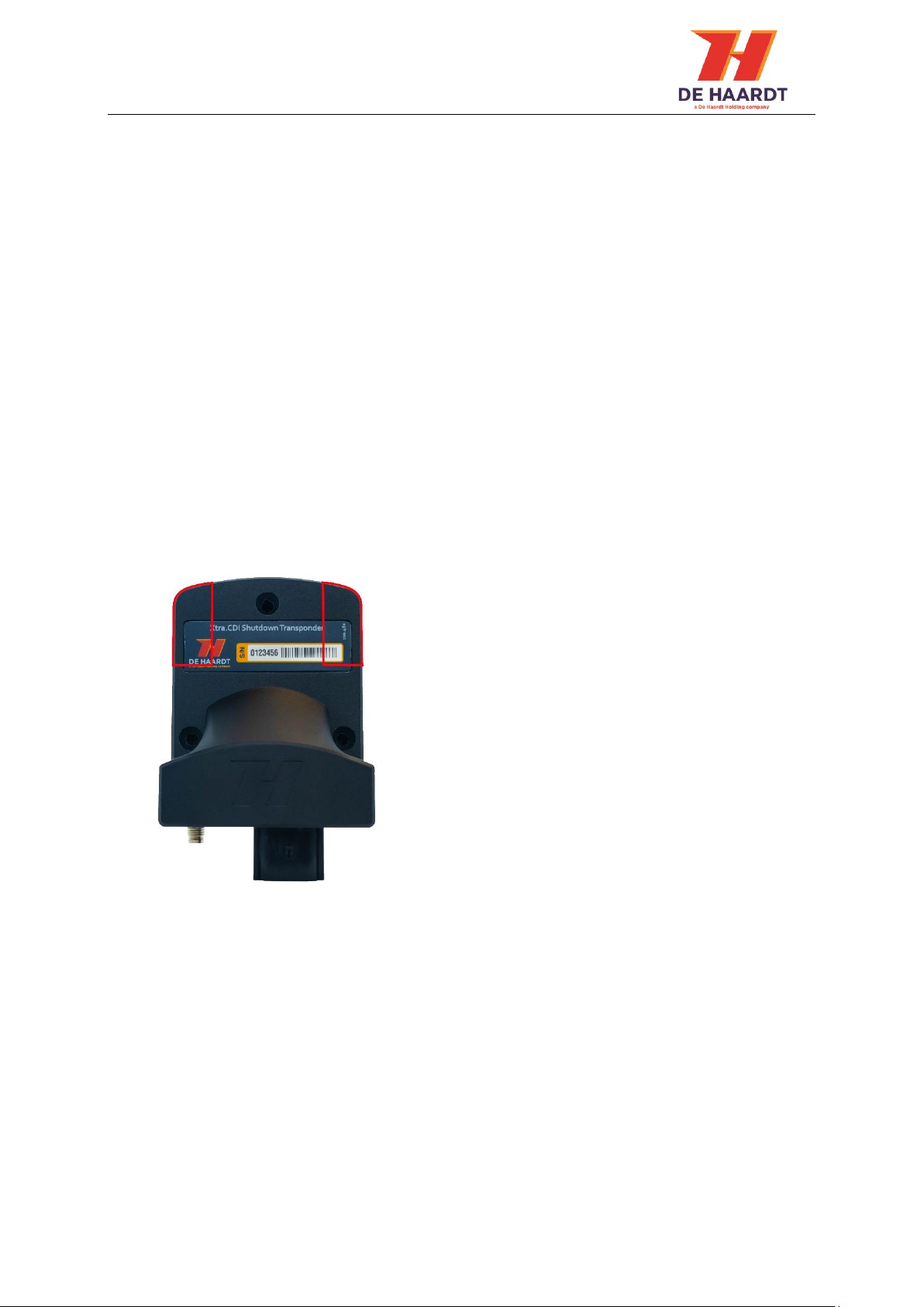
1.2.1 Mounting
Transponder is to be fitted on a flat surface with three countersunk M5 bolts and lock-nuts.
Surface can be either plastic or metal but preferably plastic. Do not overtighten the bolts as
enclosure is not allowed to deform. Optionally, if required the fixation may be improved with
double sided adhesive tape.
Mount the transponder as high as possible on the kart, preferably with connectors facing
downwards. This ensures optimum radio sensitivity all around.
To prevent radio degeneration, it is advisable to maintain a clearance to metal around the
transponder internal antennae. These are marked red in the picture below.

Xtra.CDI Shutdown Transponder - User Manual
v1.0 7
1.2.2 Connector pinout
The Xtra.CDI Shutdown Transponder features a connector to make the connections with the
engine. Each connector pin must make the correct connection to ensure the Xtra.CDI Shutdown
Transponder functions properly. See Table 1.
Pin number
Connection
Pin 1
Ignition -
Pin 2
Power +
Pin 3
Not connected
Pin 4
Ignition +
Pin 5
Power -
Pin 6
Brake switch
Table 1: Xtra.CDI Shutdown Transponder connections
1.2.3 Engine connections
Connecting an Xtra.CDI Shutdown Transponder to a go-kart engine varies depending on the type
of engine. Chapters below describe how the Xtra.CDI Shutdown Transponder must be connected
when using the Xtra.Cable Harness CDI Transponder.
The supported and tested engines are described in the sections below.
However the Xtra.CDI Shutdown Transponder might work on different
engines. Contact our support department when in doubt.
Xtra.CDI Shutdown Transponder - User Manual
v1.0 8
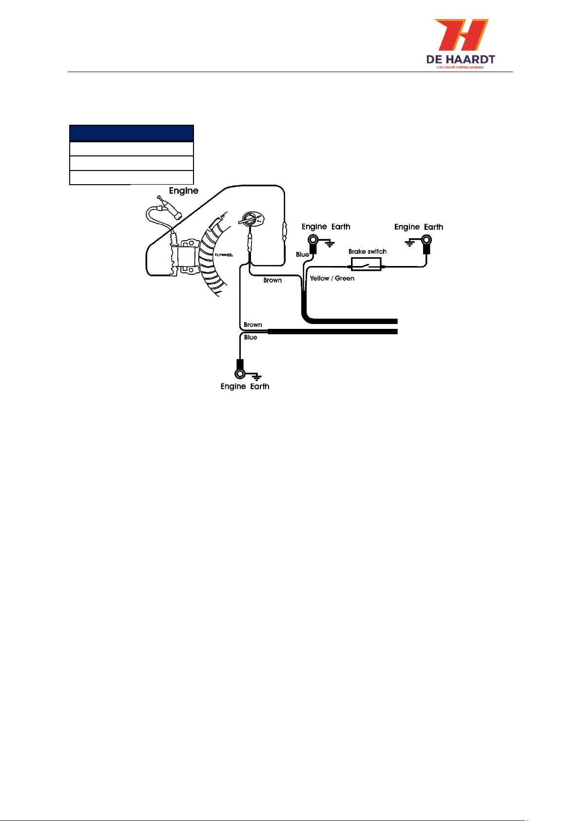
1.2.3.1 Electrical connection for conventional engines
Figure 3 shows how the Xtra.CDI Shutdown Transponder must be connected to a conventional
engine. The following Honda engines are supported and tested.
Conventional engines
GX120
GX160
GX200
Figure 3: Connecting conventional engine
Xtra.CDI Shutdown Transponder - User Manual
v1.0 9
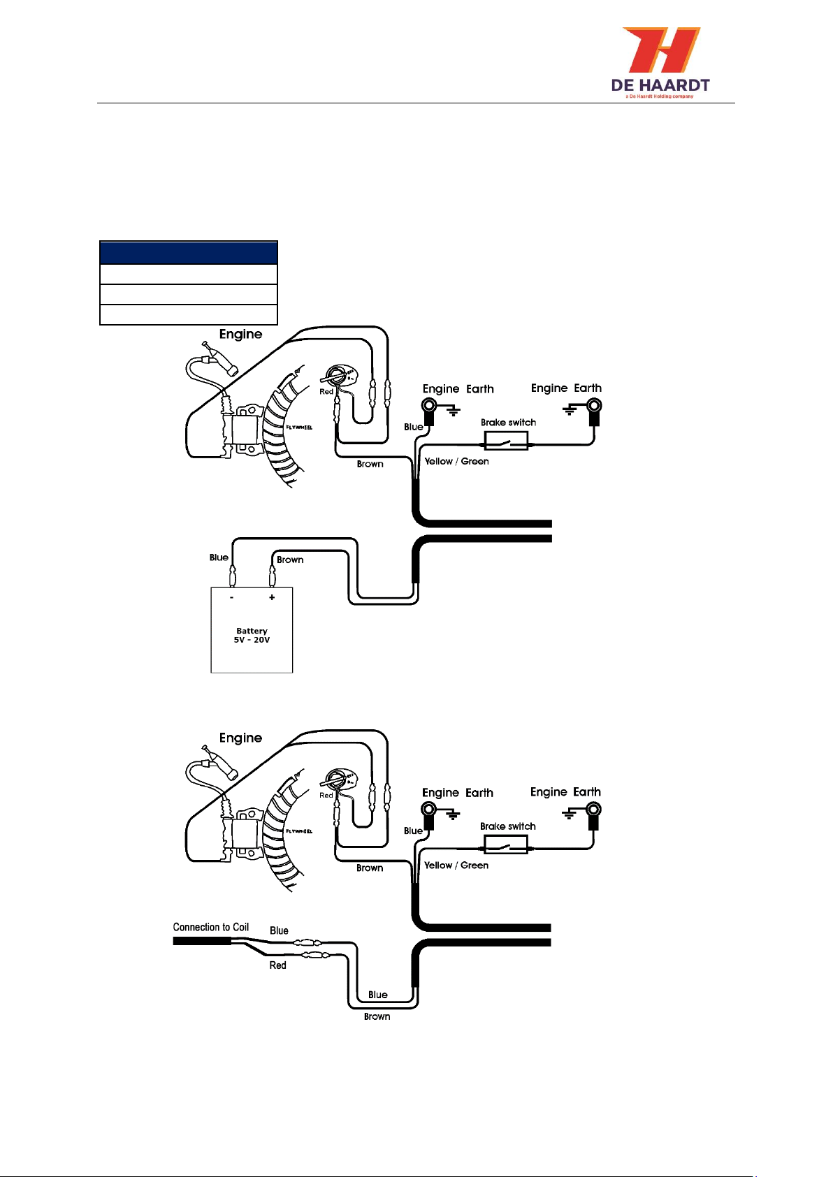
1.2.3.2 Electrical connection for CDI engine
When the Xtra.CDI Shutdown Transponder is connected to a CDI engine the connections can vary
depending on the kind of power supply. This being: a battery or a power coil.
Figure 4 shows how an engine with a battery is connected and Figure 5 shows how an engine with
a power/charge coil is connected.
The following Honda CDI engines are supported and tested.
Conventional engines
GX200
GX270
GX390
Figure 4: Connecting CDI engine with battery
Figure 5: Connecting CDI engine with coil

Xtra.CDI Shutdown Transponder - User Manual
v1.0 10
Figure 6: Xtra.CDI Shutdown Transponder
network port
1.2.4 Network port
Other De Haardt devices can be connected to the network port of the Xtra.CDI Shutdown
Transponder.
WARNING!
Always put the protection cap on the Xtra.CDI Shutdown Transponder’s
network port when this port is not used! Be sure that the protection cap is
fully covering all outside metal parts of the network port connector.
It is not allowed to connect devices to this network port which are not
approved by De Haardt!

Xtra.CDI Shutdown Transponder - User Manual
v1.0 11
2Configuration
To use the Xtra.CDI Shutdown Transponder with its full potential, it needs to be configured to the
needs of the end user. Configuring the Xtra.CDI Shutdown Transponder is done using the
Xtra.Remote Control. See the manual of the Xtra.Remote Control for instructions on configuring
the Xtra.CDI Shutdown Transponder. The various settings are described below.
2.1 Kart number (Default: last two digits of the serial number)
The kart number is used to address individual go-karts. For example: The Xtra.CDI Shutdown
Transponder is mounted on a go-kart with the number 5 written on it. Setting the kart number to
5 enables the Xtra.CDI Shutdown Transponder to be addressed through the remote with number
5.
2.2 Group (Default: all groups enabled)
Assigning multiple Xtra.CDI Transponders to a group enables the Xtra.Remote Control to control a
certain amount of go-karts. For example: two different types of go-karts drive on the same track.
One with kids and another with adults. Assigning the adult go-karts to a different group than the
kids go-karts enables the user to limit the speed of just the adult go-karts or just the speed of the
kids go-karts.
2.3 Track (Default: all tracks enabled)
When a karting venue has multiple tracks, the Xtra.CDI Shutdown Transponder can be assigned a
track. This prevents the Xtra.CDI Shutdown Transponder from reacting to messages designated to
go-karts of a different track.
2.4 Max speed limit (Default: unlimited)
A maximum speed limit can be configured in the Xtra.CDI Shutdown Transponder. Setting this limit
means the transponder can never exceed this speed limit.
2.5 Brake limit (Default: 2100 RPM)
The Xtra.CDI Shutdown Transponder can be connected to a brake switch. When the brake pedal is
pressed, the Xtra.CDI Shutdown Transponder will then limit the engine to this configured RPM.

Xtra.CDI Shutdown Transponder - User Manual
v1.0 12
3Technical specifications
This chapter describes the technical specifications of the Xtra.CDI Shutdown Transponder.
3.1 Specification overview
Description
Min
Typical
Max
Unit
Operational temperature
-10
55
°C
Operation voltage*
5
12
400
V
Input current**
5
20
60
mA
Radio Range safety band***
100
m
Radio frequency 1
433
MHz
IP code
IP65
*Max DC input voltage is 20V. A higher voltage is possible only with input pulses.
**Ambient temperature 20°C, Input current depends on the state of the product.
*** The environment is of great influence on the achieved range.

This manual suits for next models
1
Table of contents
Other De Haardt Marine Radio manuals


