De Haardt 200.910 User manual

XTRA.EMERGENCY BUTTON
User Manual
Article No. 200.910
Document version: 1.4
Date: 2022-09-06

Copyright
The information in this document is subject to change without notice. Any trademarks, trade
names, service marks or service names owned or registered by any other company and used in
this manual are property of the respective companies.
Copyright 2022
De Haardt bv
Marithaime 6
6662 WD Elst (Gld)
The Netherlands
Tel.: +31 481 353 202
Email: info@de-haardt.com
All rights reserved.
Safety
All De Haardt’s products are designed as supplement to make karting safer, but cannot replace
safe track procedures. If equipment fails, the normal operating procedure must still be adequate
to safely operate the track.
This document has been written with great care. However, the manufacturer cannot be held
responsible, either for any errors occurring in this publication or for their consequences.

Xtra.Emergency Button - User Manual
v 1.4 3
Table of Contents
1Getting started..........................................................................................................................................4
1.1 What is in the box ....................................................................................................................................4
1.2 Installation .................................................................................................................................................6
1.2.1 Mounting ...............................................................................................................................................7
1.2.2 Connecting ..........................................................................................................................................10
2Operation ................................................................................................................................................. 11
2.1 Overview ..................................................................................................................................................11
2.2 Indication LEDs .......................................................................................................................................11
3Configuration........................................................................................................................................... 12
3.1 Accessing the web interface ................................................................................................................12
3.2 Using the web interface........................................................................................................................13
3.2.1 Home....................................................................................................................................................13
3.2.2 Setup ....................................................................................................................................................14
3.2.2.1 Change the LAN settings.....................................................................................................15
3.2.2.2 Enable or disable tracks ......................................................................................................15
3.2.2.3 EMBU SPD Mode...................................................................................................................16
3.2.3 Run Time Statistics ............................................................................................................................18
3.2.4 System Tools.......................................................................................................................................19
3.2.4.1 Perform a manual firmware update.................................................................................20
3.2.4.2 Check for online firmware updates ..................................................................................21
4Technical specifications........................................................................................................................ 22
4.1 Specification overview ..........................................................................................................................22
4.2 Water and dust resistance ...................................................................................................................22
4.3 Power over Ethernet..............................................................................................................................22
5Support...................................................................................................................................................... 23
Xtra.Emergency Button - User Manual
v 1.4 4
1Getting started
This manual provides one with all the information needed to install, configure and use the
Xtra.Emergency Button.
The Xtra.Emergency Button is a product that can be used to stop or to slow down go karts and does
not disconnect electrical circuits of the go karts. The Xtra.Emergency Button is a supportive product
that could result in less dangerous situations. The Xtra.Emergency Button is designed as supplement
to make karting safer but cannot replace safe track procedures.
1.1 What is in the box
Before proceeding, make sure the box contains the following items:
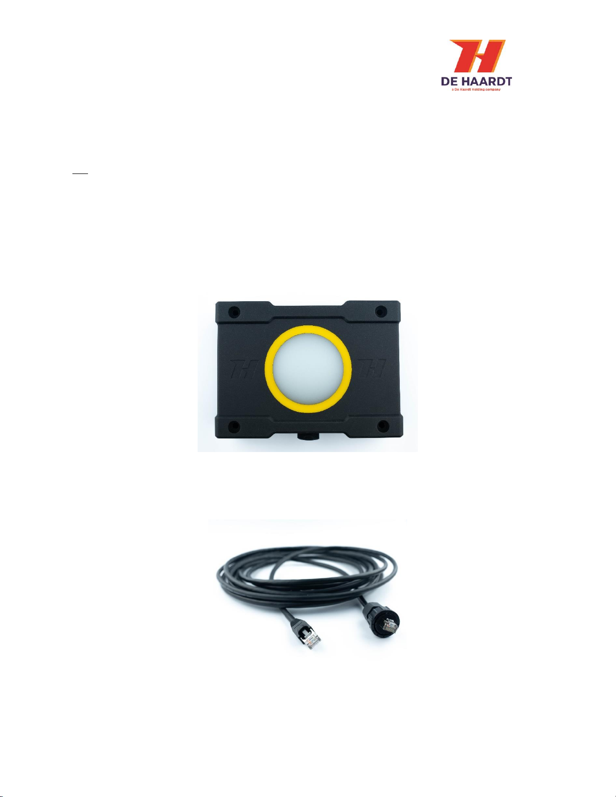
1. Xtra.Emergency Button
Figure 1 - Xtra.Emergency Button
2. 5 -meter-long Ethernet cable with a waterproof connector on one side
Figure 2 - Ethernet cable
Xtra.Emergency Button - User Manual
v 1.4 5
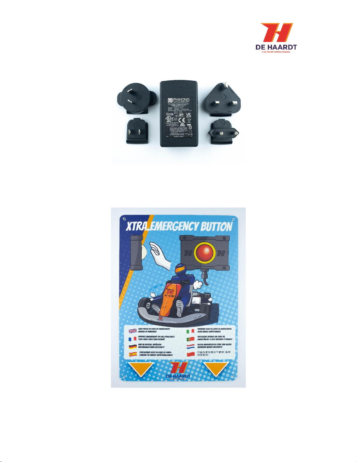
3. Power over Ethernet injector
Figure 3 - Power over Ethernet injector
4. Usage/warning board
Figure 4 Usage/warning board
Xtra.Emergency Button - User Manual
v 1.4 6
1.2 Installation
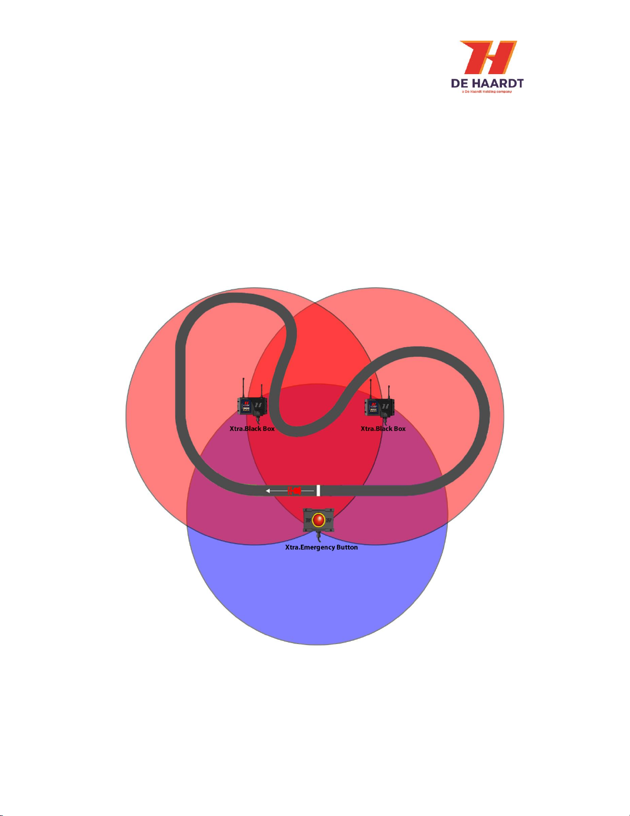
Before installing the Xtra.Emergency Button, it is important to understand that the Xtra.Emergency
Button is not able to stop or slow down go karts which are out of range. Therefore it is necessary to
prevent any blind spots by using one or more Xtra.Black Boxes. The Xtra.Black Box is capable of
receiving the messages of the Xtra.Emergency Button and forward them across a wide range on the
track.
The Xtra.Emergency Button is a product that has to be activated manually. For this reason it is
important that the Xtra.Emergency button is easy to access and installed at a location without
obstacles.
Figure 5 - Xtra.Emergency Button placement

Xtra.Emergency Button - User Manual
v 1.4 7
1.2.1 Mounting
The Xtra.Emergency Button can be mounted using 4 bolts or screws as shown in figure 5. The
Xtra.Emergency button has 4 holes, 2 holes on each side. It is necessary to mount the
Xtra.Emergency Button on flat surfaces to guarantee its functionality. By using 4 bolts or screws it is
possible to hang the Xtra.Emergency Button on flat surfaces.
Figure 4 - Xtra.Emergency Button mounting
The Xtra.Emergency Button must be mounted vertically as shown in figure 6.
Figure 5 - Mounting orientation

Xtra.Emergency Button - User Manual
v 1.4 8
Mounting the Xtra.Emergency Button on a wall or fence with steel in it may result in loss of radio
signal.
Figure 6 - Wall blocking radio signals
Mounting the Xtra.Emergency Button to a wall or plate made of metal may result
in radio dysfunctionality.

Xtra.Emergency Button - User Manual
v 1.4 9
The Xtra.Emergency Button instruction board can be mounted above the Xtra.Emergency Button with
screws. It is recommended to place the Xtra.Emergency Button Board right above the Xtra.Emergency
Button. This adds visibility and instructions to the Xtra.Emergency Button.
Figure 7 Xtra.Emergency Button Instruction Board

Xtra.Emergency Button - User Manual
v 1.4 10
1.2.2 Connecting
This chapter describes how to connect the Xtra.Emergency Button.
Figure 8 - Xtra.Emergency Button
1. Ethernet connector: Used to provide power to the Xtra.Emergency Button through power over
Ethernet and may also be used for Ethernet communication. The waterproof connector of the
supplied Ethernet cable must be connected to the Ethernet connector of the Xtra.Emergency
Button and the other end of the cable must be connected to the port labeled OUT on the power
over Ethernet injector.
Figure 9 - Power over Ethernet injector
The power over Ethernet injector features two ports labeled IN and OUT. The port labeled OUT should
be used to connect the power over Ethernet injector to the Xtra.Emergency Button using the supplied
Ethernet cable. The port labeled IN may be used to provide the Xtra.Emergency Button with access to
an Ethernet network by connecting the port to a network router or switch using an Ethernet cable.
For the power over Ethernet injector to function, it must be plugged into a wall
socket.
The side of the supplied Ethernet cable that connects to the power over Ethernet
injector as well as the power over Ethernet injector itself are NOT waterproof.
Make sure these are protected from water!

Xtra.Emergency Button - User Manual
v 1.4 11
2Operation
2.1 Overview
The front of the Xtra.Emergency Button is provided with 6 LEDs around the push button.
Figure 10 - Front with indication LEDs
2.2 Indication LEDs
The 6 LEDs on the front of the Xtra.Emergency Button will light up the push button when the
Xtra.Emergency Button has been powered on. These LEDs can have the following conditions:
-White light: Idle mode - > ready to be activated, push button is active and could be pressed.
-Red light blinking: Active mode -> the button has been pressed. Xtra.Emergency Button sends
signals to go karts. For a, in the webpage configured, duration the red light will continue
blinking.
-Red light: Active mode -> Xtra.Emergency Button sends signals to go karts. The red light is no
longer blinking instead in a stable red light and can be pressed again to disable the
Xtra.Emergency Button.
Xtra.Emergency Button - User Manual
v 1.4 12
3Configuration
The Xtra.Emergency Button can be configured using the products web interface. This chapter
describes how to access the web interface and what the different settings are.
3.1 Accessing the web interface
The web interface can be accessed using any device featuring a web browser. When the IP address of
the Xtra.Emergency Button is entered into the address bar of a web browser, the products web
interface will appear. If the IP address is unknown, the web interface can also be accessed through
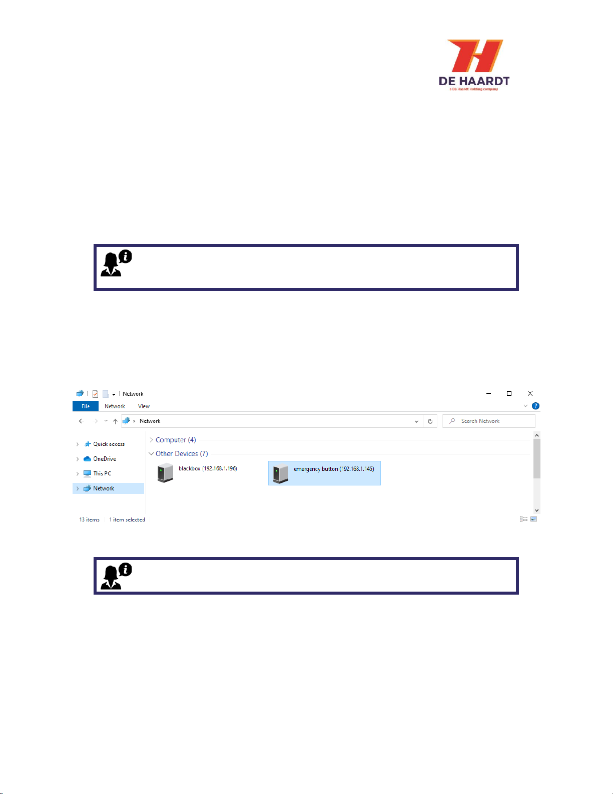
File Explorer on a Windows computer.
1. Press Windows Key + E on your keyboard to open File Explorer
2. Use the navigation pane on the left to open the Network Tab
3. In the Other Devices category, the Xtra.Emergency Button appear as in figure 11.
4. Double clicking the Xtra.Emergency Button will open the web interface using the default web
browser.
Figure 11 - Network Tab of File Explorer (Windows 10)
To be able to access the web interface, the Xtra.Emergency Button should be
connected to the same Ethernet network as the device you are trying to access
the web page from.
A firewall may hinder the detection of the Xtra.Emergency Button and therefore
prevent the product from appearing in the Network Tab of File Explorer.
Xtra.Emergency Button - User Manual
v 1.4 13
3.2 Using the web interface
The web interface is divided into 4 webpages:
1. Home: Provides an overview of the active general settings.
2. Setup: Allows the user to change the settings of the Xtra.Emergency Button.
3. Run Time Statistics: Provides statistics for support purposes.
4. System Tools: Allows the user to perform a firmware update.
The navigation bar on the left side of the web interface can be used to switch between the 4 web
pages.
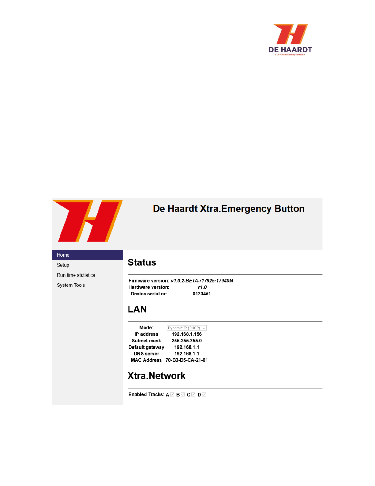
3.2.1 Home
The home webpage provides an overview of the active general settings. The current LAN and
Xtra.Network settings are displayed here. For further explanation about these settings, see 3.2.2 Setup.
The home webpage also displays the firmware version, hardware version and serial number of the
Xtra.Emergency Button.
Figure 12 - Home webpage
Xtra.Emergency Button - User Manual
v 1.4 14
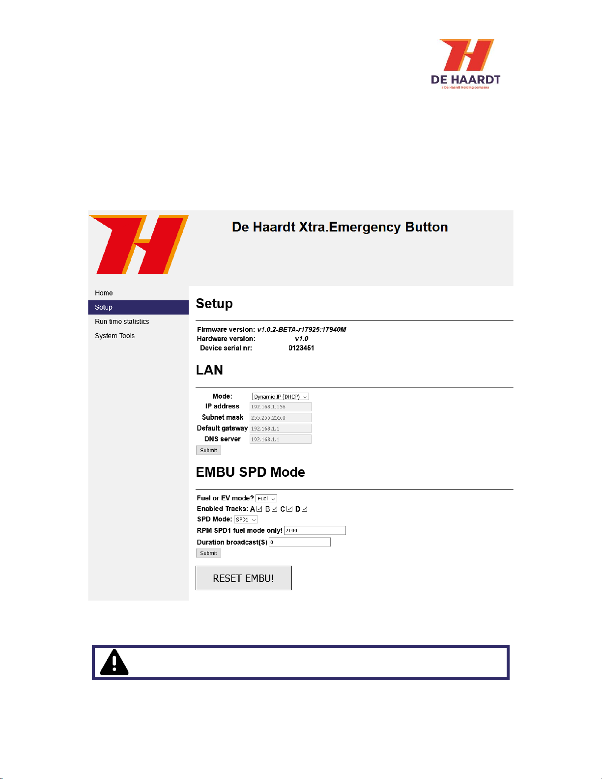
3.2.2 Setup
The setup webpage allows the user to change the settings of the Xtra.Emergency Button.
The webpage is divided into 3 sections:
1. LAN: Change the LAN settings.
2. EMBU SPD Mode: Change the function of the push button.
Each section will be explained separately in this paragraph. The setup webpage also displays the
firmware version, hardware version and serial number of the Xtra.Emergency Button.
Figure 13 - Setup webpage
IMPORTANT: Select the correct mode(Fuel or EV) for your karts or the
emergency button might not function properly.

Xtra.Emergency Button - User Manual
v 1.4 15
3.2.2.1 Change the LAN settings
In the LAN section, two modes can be selected: Dynamic IP (default) and Static IP. When the Static IP
mode is selected, the user must provide some network properties. After changing the LAN mode, the
Xtra.Emergency Button needs to be restarted for it to take effect. This can be done by temporarily
removing the power from the device or by using the restart button on the System Tools webpage.
Figure 14 - LAN section of the setup webpage
3.2.2.2 Enable or disable tracks
In the EMBU SPD Mode section, the user can indicate to which karting tracks the Xtra.Emergency
Button belongs using checkboxes. This is so that the product only responds to radio signals that are
intended for these tracks. By default, all tracks are enabled. If none of the tracks are enabled, track A
will be enabled automatically.
Figure 15 - Xtra.Network section of the setup webpage
The Static IP mode should only be selected by users with knowledge of the local
network. Entering incorrect network properties may result in loss of access to
the web interface and/or the Xtra.Emergency Button itself.

Xtra.Emergency Button - User Manual
v 1.4 16
3.2.2.3 EMBU SPD Mode
In the EMBU SPD Mode section, the function of the button can be changed from EV mode to fuel mode
and vice versa. The Xtra.Emergency Button can be used to stop or slow down go karts. Besides it is
also possible to configure the duration that the Xtra.Emergency Button will be active after the button
has been pressed. To change these functions of the push button, the following steps must been taken:
1. Select the dropdown menu at “Fuel or EV mode?” And select the preferred setting. If “Fuel
mode” is selected, make sure a valid RPM value has been filled in that corresponds the RPM
value for the preferred speed setting. Maximum value is 4500 RPM. Minimum value is 1500
RPM.
2. Enable the preferred active tracks.
3. Select the preferred speed mode.
4. Select the preferred broadcast duration time in seconds. When the value 0 has been filled, the
Xtra.Emergency Button will send continuously. The Xtra.Emergency Button has to be reset
manually to disable the active state. If a preferred duration has be configured, the
Xtra.Emergency Button will reset automatically when the duration has been passed.
5. Enter the preferred button light blink duration in seconds. After this period the
Xtra.Emergency Button will stop blinking and will be continuously red. The Xtra.Emergency
Button can at that point be disabled by pressing the button for a second time.
6. Press the submit button to save the new configuration.
Figure 16 - Safety Lighting section of the setup webpage
The RPM value must be filled in before submitting the preferred speed setting
for fuel go-karts (Fuel mode only). The Default RPM value is 2100.
Xtra.Emergency Button - User Manual
v 1.4 17
After the button has been pressed, the Xtra.Emergency Button is active and will send radio signals
until it has been reset or the preferred duration has been passed. When duration 0 (continuously
mode) has been chosen, it is possible to reset the Xtra.Emergency Button in the following ways:
-Power cycle
oRemove the Ethernet cable and put it back after a few seconds.
-Press the “RESET EMBU!” Button in de “EMBU SPD Mode” section on the webpage.
The Xtra.Emergency Button will reset and change the red lights to white lights.
Changing the configuration from continuously sending to a specified duration
may result in dangerous situations. Continuously sending is the default setting
(duration 0).
The default function of the Xtra.Emergency Button is to slow down all go karts
to SPD 1.
Xtra.Emergency Button - User Manual
v 1.4 18
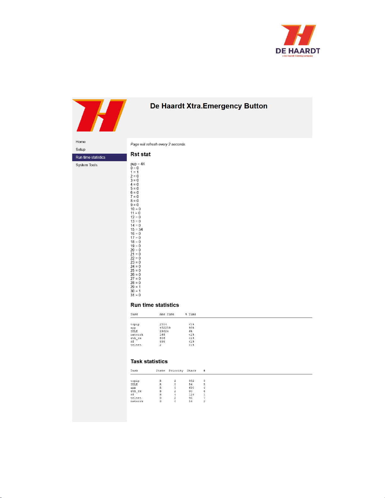
3.2.3 Run Time Statistics
The Run Time Statistics webpage provides statistics for support purposes. When there is a problem
with the Xtra.Emergency Button, a support employee of De Haardt can use this data to identify the
issue.
Figure 17 - Run Time Statistics webpage
Xtra.Emergency Button - User Manual
v 1.4 19
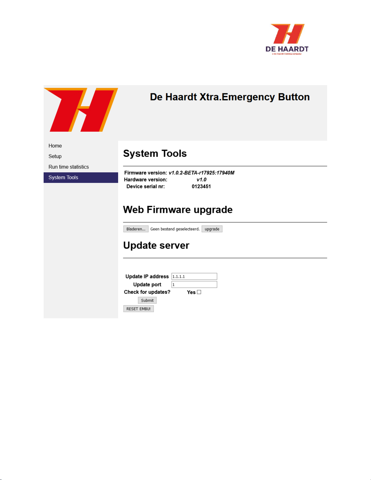
3.2.4 System Tools
The Systems Tools webpage allows the user to perform a firmware update. There are two options to
upgrade to a new firmware version: perform a manual firmware update or check for online firmware
updates.
Figure 18 - System Tools webpage

Xtra.Emergency Button - User Manual
v 1.4 20
3.2.4.1 Perform a manual firmware update
A manual firmware update can be performed in the following way:
1. In the web firmware upgrade section, click the browse file button.
2. Select the firmware update file supplied by De Haardt using the File Upload window.
3. In the web firmware upgrade section, click the upgrade button.
4. Wait for the new firmware version to be downloaded.
5. Restart the Xtra.Emergency Button. This can be done by temporarily removing the power from
the device or by using the restart button on the webpage.
Figure 19 - Web Firmware Upgrade section of the Systems Tools webpage
Figure 19 –File Upload window
Figure 20 - Firmware downloading
Do not select any file that is not supplied by De Haardt. Doing so can cause the
Xtra.Emergency Button to stop working.
If the firmware update file is not displayed in the File Upload window, try
changing the dropdown box above the “Open” and “Cancel” buttons to “All Files
(*.*)”.
Wait for the firmware download to complete or the Xtra.Emergency Button will
not be updated.
Table of contents


