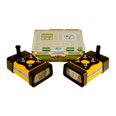
NUOVA ELETTRONICA DSP LASER User manual

DSPLSR01EN
Rev. 1.7 –Ed. 29/01/2020
DSP LASER
INSTRUCTION MANUAL
TRANSLATION OF THE ORIGINAL INSTRUCTIONS
TYPE 4 SAFETY DEVICE
WITH
VISIBLE LASER EMISSION
Revision 1.7 of 29.01.2020
NUOVA ELETTRONICA s.n.c. di Pasqui F. & C.
Via Parri ZI Moiano - 06062 Città Della Pieve - PG - ITALIA - UE
Tel. : +39 (0)578 298066 Fax: +39 (0)578 297007


Status of manual
Manual code: DSPLSR01EN
Revision: 1.7
Issue: 29/01/2020
Chronology of document revisions
Date Revision Summary of changes
12/09/2009 1.0 Draft
24/10/2009 1.1 First issue
01/12/2009 1.2 Second issue
10/12/2009 1.3 Third issue
03/02/2017 1.4 Fourth issue
16/03/2017 1.5 Fifth issue
26/11/2019 1.6 Sixth issue
29/01/2020 1.7 Seventh issue
Copyright information
Possible information about copyright


DSP LASER
DSPLSR01EN 1
1. Foreword
Purpose of this manual is to inform both the technical personnel responsible of the
installation (manufacturer or who overhauls the press brakes, from now on pointed out for
easiness in writing only with the term of manufacturer) and the user of the machine, where
the device will be installed, about the operations of assembly, installation, use and
maintenance of the equipment. The information relevant to the use of the machine must be
integrated with the information contained in this document. The instructions are addressed
to the manufacturer’s personnel charged to integrate the equipment into the press and to
the user’s personnel of the press who executes the normal working operations, once the
device is installed (use, adjustment, maintenance, etc.). The installation of the device
presupposes a minimum technical knowledge and even the compliance with the current
laws relevant to the safety in the working places and to the fire prevention.
The manual must be kept, both by the manufacturer and by the user of the machine, with
care and in a place such to be immediately available each time it is necessary.
Contact Nuova Elettronica for clarifications, explanations or to ask for possible additional
copies or updates of the manual itself.
Nuova Elettronica reserves the right to execute changes to the production and to the
manual without the obligation to update the production and the previous manuals.
1.1. General Information
This manual has been issued by the manufacturer of the equipment and constitutes an
integral part of the equipment itself.
It defines the purpose which the equipment has been manufactured for and all the
information in order to ensure a correct and safe utilization.
Nuova Elettronica, in pursuing a policy of constant development and update of the product
and combining the evolution of the “state-of-the-art” of the laser safety devices for the press
brakes, can make changes without any notice.
Nuova Elettronica declines any responsibility for changes made to the device by the user.

DSP LASER
2 DSPLSR01EN
2. Symbols used in the manual
The important information has been highlighted and accompanied by the word:
Warning:
Lack of reading this information can cause serious dangers for the
operator
Residual risk:
The information signals a risk which had been impossible to eliminate
Caution:
Indicates a situation of possible danger which, if not avoided, can cause
minor damages
Information:
Additional information not relevant to safety
Technical information of major importance is highlighted with bold font.

DSP LASER
DSPLSR01EN 3
3. Warranty
The manufacturer ensures his own products for a period of 12 months from the sale date.
The warranty covers the parts of the device, if it is demonstrated that they are faulty in
materials or assembly, respecting the following conditions:
1) With warranty we mean the replacement of all those parts which have been found
faulty for manufacturing in conditions of normal use.
Warranty is not valid if not accompanied by the copy of the invoice attesting the
purchase.
Moreover, the warranty is not valid in the following cases:
a) any kind of tampering of the device;
b) use of the device in modes not in compliance with the warnings reported in this
manual;
c) damages caused by the not suitability of the environment where the device
works and phenomena not depending on the normal operation (e.g.: wrong
voltage or frequency values of the mains);
d) repair interventions carried out by persons or Technical Service Centres not
authorized by Manufacturer;
2) The costs and the risks of the transport, of the packaging and of the possible labor
necessary for this purpose are at Purchaser’s charge.
3) The replacement of the device, as even the extension of the warranty after the
intervention for fault, is excluded.
4) No refund is foreseen for the possible inactivity period of the device during the period
necessary for the repair.
4. Technical Service
Technical and Repair Service, as the replies to the request of specific information or
explanations, are provided directly by the equipment manufacturer:
NUOVA ELETTRONICA s.n.c. di Pasqui F. & C.
Via Parri ZI Moiano - 06062 Città Della Pieve - PG - ITALIA - UE
Tel. : +39 (0)578 298066 Fax: +39 (0)578 297007
web: www.nuova-elettronica.com
e-mail: info@nuova-elettronica.com

DSP LASER
4 DSPLSR01EN
5. Contents
1. Foreword..................................................................................................................... 1
1.1. General Information ............................................................................................ 1
2. Symbols used in the manual ..................................................................................... 2
3. Warranty...................................................................................................................... 3
4. Technical Service....................................................................................................... 3
5. Contents...................................................................................................................... 4
6. Safety precautions ..................................................................................................... 6
6.1. Signals of residual risks ...................................................................................... 6
6.2. Precautions......................................................................................................... 6
6.3. Dangers of electrical kind.................................................................................... 6
6.4. Prohibitions......................................................................................................... 6
6.5. Checks................................................................................................................ 6
6.6. Spare parts......................................................................................................... 7
6.7. Decommissioning................................................................................................ 7
7. Key .............................................................................................................................. 8
8. Planning safety measures ......................................................................................... 9
9. Introduction ...............................................................................................................11
9.1. Operating cycle of a bending press-brake..........................................................13
9.2. Foreseen use of the DSP LASER device...........................................................14
9.3. Operating principle.............................................................................................15
10. Requirements necessary for the correct use of DSP LASER........................16
10.1. Command circuit of the press-brake...................................................................16
10.1.1. Start and stop......................................................................................................16
10.1.2. Inhibition..............................................................................................................16
10.1.3. Operating modes ................................................................................................17
10.1.4. Check of overtravel or stop space......................................................................25
10.1.5. Interlock of restart ...............................................................................................28
11. Residual risks...................................................................................................29
11.1. Risks due to the Laser .......................................................................................29
11.2. Risks due to mechanical dangers.......................................................................29
11.2.1. Manual sheet support .........................................................................................29
11.2.2. Blanking ..............................................................................................................30
11.2.3. Installation and uninstallation of tools.................................................................31
11.2.4. Work organization...............................................................................................31
12. Signals and plate data......................................................................................32
12.1. Light indicators: scheme and functions...............................................................32
12.1.1. Display of the phase of stop space check ..........................................................32
12.1.2. Display of the alignment with four LEDs.............................................................33
12.1.3. Alignment LED....................................................................................................33

DSP LASER
DSPLSR01EN 5
12.1.4. Display of the lock after 30 operating hours .......................................................33
12.1.5. Blanking and Exclusion LED...............................................................................34
12.1.6. LED for OSSD outputs in state ON.....................................................................34
12.1.7. LED for OSSD outputs in state OFF...................................................................34
12.1.8. Display of the selection of the operating modes.................................................34
12.1.9. Display of the Synchronism fault ........................................................................34
12.1.10. Display of the fault of the operating modes ........................................................34
12.2. Identification plates............................................................................................35
13. Installation .......................................................................................................38
13.1. Standard supply ................................................................................................38
13.2. Transport and unpackaging...............................................................................38
13.3. Mechanical installation ......................................................................................38
13.3.1. Modules: ALdc, AL1B, AL2B ..............................................................................38
13.3.2. Transmitter and Receiver ...................................................................................38
13.3.3. Setting.................................................................................................................40
13.3.4. Installation...........................................................................................................41
13.4. Electrical connection .........................................................................................43
14. Commissioning................................................................................................ 52
14.1. Power supply of the device................................................................................52
14.2. Adjustment after the installation......................................................................... 52
14.3. Check of the stop space....................................................................................55
15. Use.................................................................................................................... 56
15.1. Setting of PCV...................................................................................................56
15.2. Check of the stop space....................................................................................56
15.3. Adjustment after the change of the upper tool...................................................56
15.4. Check of the correct positioning ........................................................................58
15.5. Check of the Receiver LEDs..............................................................................58
16. Maintenance.....................................................................................................59
17. Troubleshooting guide....................................................................................59
18. Removal of the device and re-installation after repair.................................. 60
19. Technical characteristics................................................................................61
20. CE Declarations of conformity........................................................................62

DSP LASER
6 DSPLSR01EN
6. Safety precautions
6.1. Signals of residual risks
•The device DSP LASER has been designed with the aim to eliminate or reduce as most
as possible any risk for the user; however in case of improper use, conditions of limited
danger, which cannot be completely eliminated, could occur. Possible residual risks are
indicated in the following chapters of this manual.
6.2. Precautions
•The operations of installation, test and maintenance of DSP LASER must be executed
only by qualified personnel who must strictly respect the instructions reported in this
manual.
6.3. Dangers of electrical kind
•Place the connection cables in such a way to avoid accidental contacts with objects
which can damage them (hot, sharp, abrasive).
•Do not use the device in case of damaged connections cables.
•Avoid the connection cables enter in contact with water or wet surfaces.
6.4. Prohibitions
•Connecting other equipment to the power supply of DSP LASER provided by the
AL modules is forbidden.
This operation could generate an overload for the transformer, so compromising the
correct operation of it and of the circuits for the emission and the reception of the laser
beam and, as consequence, the device control functions.
•Opening of the devices
Given the typical function of the device, opening the TX, RX and AL containers and,
least of all, attempting repair operations, is forbidden. The laser beam used by this
device can be dangerous for the sight, if exposed. For the repairs, call only Nuova
Elettronica.
TX and RX must be opened only to connect the cables to the relevant clamps or to
dismount the device which must be sent to repair. In order to execute this operation,
only the rear cover must be removed.
6.5. Checks
•Check the operating voltage of the device before using it.
The operating voltage has to match the voltage of the local power grid. The operating
voltage is indicated over the plate located on the TX and RX modules or on the AL
module, if used.
The device is not disconnected from the power grid until the TX, RX and, if used, AL
modules are physically connected to the electric panel , even if the device looks like off.
Make sure that, if the ALdc or DSPdc is used, the power is derived from a power supply
device classified PELV.

DSP LASER
DSPLSR01EN 7
•Stop immediately using the device in case of penetration of liquids or objects in it.
Disconnect the device and make it is checked by qualified personnel.
In order to disconnect the device, refer to the procedure described in the chapter
relevant to the removal of the device.
6.6. Spare parts
The spare parts can be provided only by Nuova Elettronica.
6.7. Decommissioning
When you decide not to use the device DSP LASER anymore because obsolete or
irreparably faulted, execute the decommissioning making the device itself not operating and
free from dangers. Seal the device inside a robust package and provide to its disposal
operating in compliance with the current laws, asking to the local bodies charged for these
operations.

DSP LASER
8 DSPLSR01EN
7. Key
DSP LASER
=
Initials of this device;
ALdc, AL1B, AL2B
=
Initials of the power supply module. The versions ALdc and AL2B include
even the two OSSD with relay;
ESPE
=
Electro-Sensitive Protective Equipment;
OSSD
=
Output Signal Switching Devices;
TX
=
Initials of the transmitter, part of DSP LASER, which generates and
radiates the light beam;
RX
=
Initials of the receiver, part of DSP LASER, which includes the sensitive
function, the check and command function and the LED;
REDUNDANCY
=
Use of more than one device or system or parts of them with the aim to
ensure that, in case of fault of a single component in the execution of its
function, another component can execute that function;
MONITORING
=
Safety function ensuring that a safety measure intervenes if the capacity
of a component or an element in the execution of its function is
decreased;
DETECTION AREA
=
Area within which the specified test piece will be detected;
DETECTION
CAPACITY
=
Minimum size of the test piece able to be detected;
RECEPTION AREA
=
Area within which the beam generated by the transmitter is detected by
the receiver;
LEAD TIME
=
Maximum time between the moment when the test piece is inserted in the
detection area and the moment when the two OSSD switch to OFF state;
STATE OFF
=
State where the output circuit (OSSD) is open and cuts the current flow or
is at potential 0V if we consider the solid state outputs;
STATE ON
=
State where the output circuit (OSSD) is closed and allows the current
flow or is at potential 24V if we consider the solid state outputs;
COLLIMATION
=
Procedure allowing the alignment of the laser beam generated by TX at
the reception area of RX;
BENDING LINE
=
Line pointed out by the tip of the punch along all the press;
BENDING AXIS
=
Axis of the section perpendicular to the punch length;
BENDING
SURFACE
=
Surface of sliding of the bending line during the movement of the punch;
OVERTRAVEL
=
Space covered by the mobile member after the interception of the
detection area of DSP LASER, defined in this manual even with the term:
”STOP SPACE”;
SAFETY
DISTANCE
=
Distance between the punch tip and the lower edge of the detection area,
equal to the sum of the maximum overtravel plus 5 mm;
INHIBITION
=
Automatic and temporary interruption of the safety function by the parts of
the command system relevant to the safety.
BLANKING
=
Function inhibiting part of the detection area;
PMSM
=
Maximum Top Dead Centre: highest point of the stroke reachable by the
mobile cross-bar.

DSP LASER
DSPLSR01EN 9
PMS
=
Top Dead Centre: highest point of the stroke generally set by the numeric
control, to achieve the wished bend.
PCV
=
Speed Change Point: point of the closing stroke where the change from
fast approaching speed to working speed, lower than or equal to 10
mm/sec, takes place.
PMI
=
Bottom Dead Centre: lowest point of the stroke of the mobile cross-bar
generally set by the numeric control, to achieve the wished bend.
8. Planning safety measures
The device DSP LASER has been designed following the indications provided by the rules:
CEI EN 61496-1:2014 and CEI EN 61496-2:2014, it can be classified as ESPE of type 4.
ISO 13849-1:2015, it can be classified as PL=e; SIL3.
The laser contained in DSP LASER is classified as CLASS 1M according to the rule CEI EN
60825-1:2015.
DSP LASER, if correctly installed and used as described in this Manual, is in compliance
with the prescriptions of:
•Machinery Directive 2006/42/CE and relevant rules and reference specifications:
oCEI EN 61496-1:2014 and CEI EN 61496-2:2015
oUNI EN 12100:2010,
EN 12622:2014, CEI EN 60204-1:2006, CEI EN 60825-1:2015
•Low Voltage Directive 2014/35/UE and relevant reference rules
oCEI EN 61496-1:2014
oCEI EN 60204-1:2006
•Electromagnetic Compatibility Directive 2014/30/UE and relevant reference rules
oCEI EN 61496-1:2014
oCEI EN 61000-6-3 :2007 + A1:2011 e IEC 61000-6-2 :2016
•The transformer has been designed in compliance with the rule CEI EN 61558-
1:2006.

DSP LASER
10 DSPLSR01EN
The transmitter generates the emission of a modulated visible laser light which, reaching
the receiver, creates a detection area and make this activates the passage to the state ON
of the two OSSD. We underline that the activation of the receiver is made possible only by
the emission generated by the transmitter which is electrically connected to. An emission
generated by an identical transmitter, but not electrically connected with the receiver cannot
activate it.
Fig. 8.1 Principle scheme
In “state ON” the device DSP LASER is in the phase of active control of the equipment
during its operation, while in “state OFF” DSP LASER has already intervened on the
equipment, deactivating its command mechanisms due to the occurrence of a possible
danger condition, the intrusion of an element into the detection area.
DSP LASER is realized with:
•two independent microprocessors to implement the function of control of the detection
area, of command of the outputs and, in general, of monitoring of the system;
•two safety solid-state OSSD switching devices protected against the short-circuit.
This type of circuit presents a high redundancy level, with double circuits, which ensures
what required by the rule CEI EN 61496-1:2014 to a ESPE device of type 4; in detail, in the
normal operation the two OSSD switch to state OFF (in the lead times), when one of the
following conditions occurs:
•an intrusion in the detection area
•a lack of power supply
•after 30 hours of continue operation
In any condition of dangerous fault of DSP LASER itself, at least one of the two OSSD
switches to state OFF (in the lead times) and maintains this state until when the defect has
been removed.
The device DSP LASER is provided with a control circuit which, if interfaced with proper
position detectors installed on the press-brake, can implement a function of automatic
monitoring of the overtravel in compliance with EN 12622:2014.
TX
RX
LASER BEAM

DSP LASER
DSPLSR01EN 11
9. Introduction
The safety device DSP LASER is a visible laser emission guard which, inserted in a more
general control system, contributes to protect the operator in the use of press brakes for the
cold working of the metals and is constituted by:
•one transmitter DSP LASER TX powered at 24Vac or 24Vdc,
•one receiver DSP LASER RX powered at 24Vac or 24Vdc which moreover includes:
the logic for the control of the operation modes, the function of automatic monitoring of
the overtravel and the two solid-state outputs OSSD,
•one DSP LASER AL module (optional) with a series of variations.
Each of them is enclosed within its own case.
The activation of the receiver is made possible only by the emission generated by the
transmitter, which is electrically connected to by the synchronism. An emission generated
by an identical transmitter, but not electrically connected with the receiver, cannot activate
it.
Main task of “DSP LASER” is detecting, within the limits defined by the detection capacity of
the instrument, the intrusion of any opaque physical element into the “detection area”. The
detection area can be defined as a “laser light solid” which starts from the transmitter and
arrives to the receiver and whose section is represented in Fig. 9.1. The interruption of the
laser beams illuminating the receiving elements, causes the detection of the occurred
interruption. The detection of the interruption of one or more of the receiving elements is
then managed by the system to issue or not the passage to state OFF of the OSSD outputs.
The device has been then designed to activate, in dangerous conditions, the functions for
the stop of the movement of the dangerous parts.
Fig. 9.1 Whole detection area
These functions have been realized providing, in output from the two OSSD, two different
ON/OFF electrical signals. The state ON corresponds to the condition for which the DSP
LASER system does not detect the conditions for which the downwards movement of the
machine must be inhibited or stopped, while the state OFF detects them. Various can be
the causes for which the outputs are set to the state OFF. The main ones are: the lack of
collimation between the two TX and RX components (caused, for example, by the intrusion
of an element into the detection area), the lack of power supply to DSP LASER, 30 hours of
continue operation, failed check of the stop space, failure of the DSP LASER equipment
itself.
The main causes of fault or wrong operation are signalled by a precise configuration of the
LEDs present in RX. For information see par.12.1.
The OSSD outputs, properly inserted in the electric circuit of command of the dangerous
part of the equipment, enable, in ON state, the possibility to command the movement (start
function) and, vice versa, to inhibit or stop it in OFF state (stop function).

DSP LASER
12 DSPLSR01EN
At last, the management of the procedures of stop, suspension and reactivation of the
machine are entrusted to the main control board of the machine itself.
DSP LASER is available in more versions which differ for the following main characteristics:
•Blanking type: “Stop&Go” or with “Enabling by operator”
•Central receiver: optional or in different positions, allowing the use with machines
whose stop space is included within ranges of different values
•Function of check, at switch-on, of the presence/absence of the stop space
•24Vdc power supply for TX and RX modules
•24Vdc power module and OSSD relay outputs (ALdc)
•Power supply module with filter and power supply transformer by 220Vac or 24Vac
(AL1B)
•Power supply module with filter and power supply transformer by 220Vac or 24Vac
and OSSD outputs with relay (AL2B)
The codes identifying RX module of DSP LASER with the corresponding configuration are:
The codes identifying TX module of DSP LASER with the corresponding configuration are:
RX x x x x
A: Blanking mode “Enabling by Operator”
B: Blanking mode “Stop & Go”
See Chp. 10.1.3 Pag. 17
0: Opt. Rec. Ele absent S.A.: between 0 and 7mm
2: Opt. Rec. Ele present S.A.: between 3 and 14mm
See Chp. 10.1.4 Pag. 25
0: Function STOP SPACE CHECK ABSENT
1: Function STOP SPACE CHECK PRESENT
See Chp. 10.1.4 Pag. 25
RX : Receiver module
0: Function RESTART INTERLOCK ABSENT
1: Function RESTART INTERLOCK PRESENT
See Chp. 10.1.5 Pag. 29
TX x
TX : Transmitter Module
0: TX suitable to RX with option 0 of S.A.
(0: when RXA0xx or RXB0xx is used)
1: TX suitable to RX with option 2 of S.A.
(1: when RXA2xx o RXB2xx is used)
dc : 24Vdc power supply

DSP LASER
DSPLSR01EN 13
The codes identifying AL module of DSP LASER with the corresponding configuration are:
The examples here below help to order the proper DSP model.
If you wish to order one DSP LASER module for a machine with stopping distance of
10mm, out-of-stroke test, anti-repetition pedal, Blanking of type A and 24Vdc power supply,
the proper code to order is: RX A211 DC.
As consequence, you have to associate the transmitter TX 1.
If you wish the solid state outputs, the auxiliary AL module is not necessary. Otherwise, if
you wish the relay outputs, even the ALdc module has to be ordered.
If you wish to order one DSP LASER module for a machine with stopping distance of 3mm,
WITHOUT out-of-stroke test, WITHOUT anti-repetition pedal, with Blanking of type B and
230Vac power supply, the proper code to order is: RX B000.
As consequence, you have to associate the transmitter TX 0.
If you wish the solid state outputs, the auxiliary module AL1B 230Vac will be necessary.
Otherwise, if you wish the relay outputs, the AL2B 230Vac module shall be ordered.
For the details relevant to the electrical connection of DSP LASER, see chapter 13.4.
9.1. Operating cycle of a bending press-brake
Here below the operating diagram of the working cycle of a hydraulic bending press-brake
with closing from above is schematically presented.
States of the cycle
Abbreviation
Cycle
Maximum top dead centre
Top dead centre
PMSM
PMS
Speed change point
PCV
Decompression point
PD
Bottom dead centre
PMI
The normal operating cycle foresees the start from the top dead centre (PMS), which does
not necessarily coincide with the maximum top dead centre (PMSM); in fact, in order to
minimize the down times, the stroke of the mobile table is generally limited to the possible
minimum value compatibly with the shape, the size and the bends to execute on the piece.
The pressure of a dead-man device (generally a pedal) commands the closing movement
with fast speed (faster than 10 mm/s) up to PCV, where the speed is automatically
decreased to a value lower than or equal to 10 mm/s. This speed limit is kept for the entire
closing stroke under the PCV until the end of the pressing action. Once the decompression
is ended, the punch automatically goes to the PMS.
AL x
dc : Module powered at 24Vdc, relay OSSD
1B : Module with power supply transformer of 230Vac or
24Vac and network filter
2B : Module with power supply transformer of 230Vac or 24Vac, network
filter and OSSD with relay (1NA contact for each output)
AL : Power supply Module

DSP LASER
14 DSPLSR01EN
DSP LASER is connected to the press command circuit in such a way that, if intercepted, it
stops the mobile table only during the fast approaching phase (from PMSM/PMS to PCV).
In this way, it ensures the safety of the operator against the mechanical dangers (due to the
approaching movement of the punch to the die) in the area of the dies:
•squashing and/or cutting danger between the punch itself and the die or the piece in
work.
During the working phase (speed lower than or equal to 10 mm\sec), going from PCV to
PMI, the system is inhibited and does not protect the operator against the danger described
in the previous point and from the dangers relevant to the movement of the piece in working
under the pressing strength of the punch:
•danger of squashing among the tools, between the piece and the upper tool or
between the piece and the mobile table;
•danger of crash of the piece (bending movement).
In the same way, during the opening movement of the tools, the protection system is
inhibited. The physical arrangement of the detection area, placed under the upper tool,
makes the system cannot give protection against the dangers due to opening movement,
among which:
•danger of squashing between mobile table and fixed parts of the press-brake;
•danger of crash due to the fall of the worked piece.
9.2. Foreseen use of the DSP LASER device
The DSP LASER device has been designed to create, by means of the laser beam emitted
by the transmitter and picked up by the receiver, a detection area (volume) for the
protection of the operator who enters in it.
Warning:
DSP LASER provides protection to the operator only stopping the
movements in progress of the upper table. Then, it cannot be used in
case of projection of material. Then pay special attention to the
choice of the material to work, of the tools and to the possible
presence of foreign bodies within the tool movement area. The
transparent tools entering the detection area are not detected.
The device has been designed and manufactured in order to ensure protection to the
operator, who accesses in front of the die area of a bending press-brake, against the
dangers due to the movement of the mobile table during the high-speed downstroke phase.
The interception of the DSP LASER detection area by the operator during the fast closing
movement stops the movement of the mobile table before the tool fixed to it can reach the
operator, who however must know the risks relevant to the work on this type of press-
brakes. Anyway, the device does not replace the necessary training of the personnel and
information about the residual risks highlighted in chp. 11 Residual risks.
The correct use of the device foresees the mechanical installation of the transmitter and of
the receiver on the upper table in such a way that the detection area is located near the
punch. In case of machine with closing from above, the system moves with the mobile table.
The electrical installation must be based on the detection of the continuity/interruption of the
detection area which determines the state ON / OFF of two electrical signals made available
by DSP LASER and which can be used for the control of the dangerous movements of the
press-brake.

DSP LASER
DSPLSR01EN 15
Whichever use different from those clearly allowed and pointed out in this use and
maintenance manual of DSP LASER is, and must be considered, forbidden; because of
these utilisations not allowed and/or unforeseen by NUOVA ELETTRONICA s.n.c. of Pasqui
F. & C., any type of explicit or implicit form of warranty expires, as even any responsibility
for possible accidents which could occur.
9.3. Operating principle
The sensors present on the receiver, as depicted in the cross-section view of Fig 9.2, being
illuminated by the laser light emitted by the transmitter, form the detection area located
under the upper tool of the press-brake and which moves with this, being mechanically fixed
to it.
Fig 9.2 Detection areas placed on the machine
The protection horizontal surface is located, from the top of the tool, at a safety distance
equal to the stop space of the machine + 5mm.; it is then clear that the safety area
precedes the movement of the upper tool of a such space to allow the tool can be stopped
without squashing any opaque object possibly present between it and the lower tool. In fact,
the object possibly present under the protection area, once penetrated the area, would
issue the command to stop the machine, which stops within a space called “stop space”. As
the command would have been issued at a distance equal to “stop space”+ 5mm, the tool
would ends its stroke at 5mm from the object which has possibly entered the protection
area, without even brushing against it.
For machine with stop space greater than 7mm and up to 18mm, the device with optional
central sensor must be used, in such a way to ensure the operator cannot put the fingers
between the tip of the upper tool and the protection area without these are detected.
The detection area is subdivided in three different areas: a front area (towards the
operator), a central area (under the tip of upper tool slightly moved towards rear part of the
press-brake) and a rear area (towards the rear of the press-brake).

DSP LASER
16 DSPLSR01EN
Area
Task
frontal
It protects the operator’s fingers too close to the working area; moreover it protects
against the risk of squashing between the die edge and the tip of the upper tool.
This area can be inhibited for specific workings.
central
It protects the operator against the squashing between the tip of the upper tool and the
sheet/die.
rear
It forbids the squashing between the tip of the upper tool and the backgauges.
This area can be inhibited for specific workings or in case of interception of the
backgauges.
10. Requirements necessary for the correct use of DSP LASER
10.1. Command circuit of the press-brake
10.1.1. Start and stop
The closing stroke of the press-brake must be commanded by a three-position dead-man
command device (e.g. pedal). The released device (position n.1) must generate a stop
signal; the pressure of the actuator (position n.2) commands the closing movement of the
tools; while the further actuation beyond a greater-pressure point (position n.3) stops again
the mobile table. The passage from position n. 3 to position n. 1 must not generate a start
command.
No cycle of the press-brake must be able to be started using the DSP LASER device itself,
but a proper command device must be always foreseen.
The interruption of the detection area during the fast approaching phase of the tools (speed
greater than 10 mm/s) must stop the closing movement of the table.
The new closing must take place only after that the operator has released and operated
again the command device. If the detection area remains interrupted, it must be possible to
command the closing at a decreased speed (lower than or equal to 10 mm/s) in
combination with the three-position dead-man command (see chp. 10.1.2 Inhibition and
10.1.3 Operating modes).
No closing movement must be possible at a speed greater than 10 mm/s while an object or
any part of the body (e.g. finger) interrupts an active part of the system interception field.
The function to start and stop the movements must be realized by the command circuit of
the machine with a safety level equivalent to that of the DSP LASER device, as prescribed
by EN 12622:2014.
10.1.2. Inhibition
The DSP LASER device creates a detection area between the dies. The interception of this
area must immediately stop the dangerous movements of the machine.
The inhibition of the stop signal produced by DSP LASER during the closing stroke of the
press-brake must be possible only if the closing speed has been previously decreased to a
value lower than or equal to 10 mm/s. The control circuit of the press-brake must be able to
make the press-brake reaches the decreased speed in safe way. Only as consequence of
this condition, the intervention of DSP LASER can be inhibited.
Table of contents
Other NUOVA ELETTRONICA Safety Equipment manuals
Popular Safety Equipment manuals by other brands

Innotech
Innotech String 1 Basic INSTRUCTIONS FOR USE AND TEST MANUAL

ROCK
ROCK RVL-125 user guide

auto maskin
auto maskin Marine Pro. 400 Series installation manua

Petzl
Petzl CARITOOL P42 quick start guide

AUSTRIALPIN
AUSTRIALPIN FISH manual

Powerfix Profi
Powerfix Profi HG01477A-1 Operation and safety notes