DE-STA-CO MDE Series User manual

INSTALLATION MANUAL
MDE-SERIES INDEXDRIVES
MODELS
MDE600M
MDE700M
MDE900M

1
Contents
1IDENTIFICATION .............................................................................................................................................................. 3
2INSTRUCTIONS FOR USE .................................................................................................................................................. 6
3PRODUCT SAFETY ............................................................................................................................................................ 9
3.1 TRAINING OF THE PERSONNEL .............................................................................................................................................. 10
3.2 PRESENTATION OF SAFETY PRECAUTIONS................................................................................................................................ 10
3.3 SYMBOLS ON THE MACHINE ................................................................................................................................................. 11
3.4PERSONAL PROTECTIVE EQUIPMENT (PPE) ............................................................................................................................. 11
4MACHINE DESCRIPTION ................................................................................................................................................ 12
4.1 PRESENTATION AND IDENTIFICATION ..................................................................................................................................... 12
Figure 1 Unit.......................................................................................................................................................................... 12
Figure 2 Access ...................................................................................................................................................................... 12
4.2 INTENDED USE .................................................................................................................................................................. 13
4.3 FORESEEABLE IMPROPER USE ............................................................................................................................................... 14
4.4 DESIGN AND COMPONENTS OF THE MACHINE.......................................................................................................................... 15
Front and Top View ............................................................................................................................................................... 15
Section and Side View ........................................................................................................................................................... 16
Bill Of Materials .................................................................................................................................................................... 17
4.5 DESCRIPTION OF FUNCTION ................................................................................................................................................. 17
4.6 PLACES OF WORK OF THE OPERATING PERSONNEL .................................................................................................................... 17
4.7 HAZARD ZONES ................................................................................................................................................................. 18
4.8 SAFETY AND MONITORING INSTALLATIONS ............................................................................................................................. 20
4.9 WARNING DEVICES............................................................................................................................................................ 20
4.10 TECHNICAL DATA .............................................................................................................................................................. 20
Recommended Oil and Quantity ........................................................................................................................................... 21
Grease ................................................................................................................................................................................... 22
5TRANSPORT .................................................................................................................................................................. 22
5.1 TRANSPORTING MACHINE AND MACHINE PARTS..................................................................................................................... 22
5.2 UNPACKING ..................................................................................................................................................................... 23
5.3 HANDLING ....................................................................................................................................................................... 23
Markings and Weight............................................................................................................................................................ 24
Approved Transportation Equipment & Procedures ............................................................................................................. 24
Transportation Inside of Packaging ...................................................................................................................................... 24
Table 2 Approximate weights of MDE models with reducer ................................................................................................. 24
Transportation Outside of Packaging ................................................................................................................................... 25
Transportation Damage ........................................................................................................................................................ 25
Intermediate Storage ............................................................................................................................................................ 25
6INSTALLING AND COMMISSIONING .............................................................................................................................. 26
6.1 INSTALLATION AND CONNECTION.......................................................................................................................................... 26
Installation Safety Protocol ................................................................................................................................................... 26
Installation Prerequisites....................................................................................................................................................... 27
Installation of Unit ................................................................................................................................................................ 28
Installation ............................................................................................................................................................................ 28
Installing the Base Plate or Frame ........................................................................................................................................ 28
Attach Unit to Base-Plate...................................................................................................................................................... 29
Manual Adjustment of Unit................................................................................................................................................... 29
Installation of Additional Components.................................................................................................................................. 30
6.2 COMMISSIONING .............................................................................................................................................................. 31

2
6.3 SET-UP AND TOOLING......................................................................................................................................................... 31
Packaging Disposal ............................................................................................................................................................... 32
Recommissioning .................................................................................................................................................................. 35
7OPERATION ................................................................................................................................................................... 35
7.1 OPERATING AND DISPLAY ELEMENTS...................................................................................................................................... 35
7.2 OPERATION OF THE MACHINE .............................................................................................................................................. 36
8SERVICE AND MAINTENANCE ........................................................................................................................................ 37
8.1 CLEANING THE MACHINE..................................................................................................................................................... 38
8.2 PROCESS MEDIA ................................................................................................................... ERROR!BOOKMARK NOT DEFINED.
8.3 MAINTENANCE SCHEDULE................................................................................................................................................... 39
Gearmotor Check .................................................................................................................................................................. 41
MDE Lubrication.................................................................................................................................................................... 41
Oil Change Intervals .............................................................................................................................................................. 41
Recommended Oil and Quantity ........................................................................................................................................... 41
Grease ................................................................................................................................................................................... 42
8.4 TROUBLESHOOTING AND FAULT CORRECTION ......................................................................................................................... 42
Symptom: Indexer appears inaccurate.................................................................................................................................. 42
Symptom: Looseness in one dwell only ................................................................................................................................. 42
Symptom: Looseness in all dwells ......................................................................................................................................... 42
Symptom: Indexer is noisy..................................................................................................................................................... 43
Symptom: Premature wear of cam followers........................................................................................................................ 43
Symptom: Output movement is noisy and erratic................................................................................................................. 43
8.5 SPARE AND WEAR PARTS.................................................................................................................................................... 44
Spare Parts list ...................................................................................................................................................................... 44
Input Oil Seal Replacement Consideration ............................................................................................................................ 44
Cam Follower Replacement Consideration........................................................................................................................... 44
Input Shaft and/or Cam Replacement Consideration ........................................................................................................... 44
Follower Wheel and/or Output Bearing Replacement Consideration ................................................................................... 44
8.6 DISASSEMBLY ................................................................................................................................................................... 46
8.7 INSPECTION...................................................................................................................................................................... 46
8.8 OIL SEAL REPLACEMENT ...................................................................................................................................................... 47
Oil seal removal..................................................................................................................................................................... 47
Oil seal installation................................................................................................................................................................ 47
8.9 CAM FOLLOWER REPLACEMENT ............................................................................................................................................ 48
Cam follower cartridge removal ........................................................................................................................................... 48
Cam follower removal from cartridge ................................................................................................................................... 49
Cam follower installation into cartridge ............................................................................................................................... 49
Cam follower cartridge installation....................................................................................................................................... 50
9SHUTDOWN, STORAGE AND DISPOSAL ......................................................................................................................... 51
9.1 SHUTDOWN ..................................................................................................................................................................... 51
9.2 STORAGE CONDITIONS........................................................................................................................................................ 51
9.3 DISPOSAL......................................................................................................................................................................... 52
10. ANNEX ............................................................................................................................................................................. 53
Declaration of Incorporation................................................................................................................................................. 53
NORD DRIVESYSTEMS ........................................................................................................................................................... 54
SEW-EURODRIVE................................................................................................................................................................... 56
TL6615 EXTRACTION TOOL PAGE 1 OF 2 .............................................................................................................................. 57
TL6615 EXTRACTION TOOL PAGE 2 OF 2 .............................................................................................................................. 58
11. DECLARATION OF INCORPORTATION............................................................................................................................... 59

3
1 Identification
Product identification
Product
identification
Manufacturer:
DE-STA-CO CAMCO PRODUCTS
Street:
1444 SOUTH WOLF ROAD
City:
WHEELING, ILLINOIS 60090 USA
Tel.:
+1-847-459-5200
Fax:
+1-847-459-3064
E-mail:
Internet:
http://www.destaco.com
After-Sales Service
address:
Machine designation:
INDEX DRIVE MODEL
Type designation:
MDE-SERIES
Serial No.:
SEE NAME PLATE
Year of construction:
2015
Product No.:
SEE NAME PLATE
P.O. No.:
Order No.:
Sales:
DE-STA-CO Europe GmbH
Hiroshimastraße 2
61440 Oberursel
Germany
Manufacturer:
DE-STA-CO Camco Products
Industrial Motion Control, LLC
1444 South Wolf Road
Wheeling, IL 60090
USA

4
Document identification
Document
identification
Version:
1.0
Creation date:
IV 2015
Last revision:
NA
Product Identification
Product:
Model No.:
MDE600M, MDE700M MDE900M
Serial No.:
Year of construction:
2015
Sales:
DE-STA-CO Europe GmbH
Hiroshimastraße 2
61440 Oberursel
Germany
Manufacturer:
DE-STA-CO Camco Products
Industrial Motion Control, LLC
1444 South Wolf Road
Wheeling, IL 60090
USA
2.1 Justification for classification in accordance with the Machinery Directive
The products from the Automation division are divided into the following classes:
Index drive models.
In accordance with the Machinery Directive 2006/42/EC, the above-mentioned products are classified as
incomplete machines according to Article 2g). This results in the necessity to produce the technical
documentation in accordance with Annex VII B and the declaration of incorporation in accordance with Annex
II B.
Justification for classification as an incomplete machine:
The machine as such does not fulfil a particular function.
The pneumatic/hydraulic/electric control system is not included in the scope of supply.
The machine is intended for incorporation into other machines or to be assembled with them.

5
There are no elementary protection devices at the man-machine interface

6
2 Instructions for Use
Purpose of the document
Purpose of
the document
The operating manual is intended to help the user familiarise himself with the machine
and its intended application possibilities. The operating manual contains important
information on the safe, proper and profitable operation of the machine. Observation
of this information will help avoid hazards, reduce repair costs and standstill times and
increase the reliability and service life of the machine.
Notes on precautionary measures to be taken by the machine owner:
Employ only personnel with the necessary qualification for the work in hand to
operate the machine.
Define clear responsibilities and authorities for the operating and maintenance
personnel.
Supplement the operating manual with rules derived from the national
occupational health and safety and environmental protection regulations (e.g.
work organisation).
Instruct the personnel to observe the operating manual and its additions, and
check compliance from time to time. Have one copy of the operating manual
available at the place of operation of the machine at all times!
Operate the machine only when it is in a technically safe condition, and take
measures to maintain this safety.
In addition to the operating manual, the binding accident prevention regulations
applicable in the country of operation and at the place of work must also be observed.
In addition, the acknowledged engineering rules for safe and proper working must be
observed.

7
Target groups
Target groups
a) The owner as superordinate legal entity is responsible for the intended use of
the machine and for the training and employment of the authorised persons. He
lays down the binding competencies and authorities of the authorised persons
for his company.
b) According to the latest Machinery Directive, the operating personnel are the
persons responsible for installation, operation, set-up, maintenance, cleaning,
repair or transport of machines.
c) A specialist is a person who thanks to his technical training, know-how and
experience is able to assess the assigned duties and to recognise potential
hazards. Furthermore, this person has know-how of the applicable regulations.
Only qualified specialists or such persons considered by the owner to be
capable are to be employed.
d) Trained/instructed persons are persons who have been instructed and
possibly trained in the assigned duty and in the potential dangers associated
with improper behaviour. The person has also been instructed about the
necessary protective devices and safety measures. Persons undergoing
training, instruction or familiarisation and persons undergoing general training
may only work under the constant supervision of an experienced person.

8
Target groups
Liability and warranty
Liability
and
warranty
All information and tips given in this operating manual are given to the
best of our knowledge and belief and on the basis of our experience
and findings to date. The original version of this operating manual was
drawn up in English and was examined technically by us. The
translation in the respective national/contract language was produced
by an acknowledged translation agency.
This operating manual was compiled with the greatest care. Should
you discover any gaps and/or errors, however, please inform us
accordingly in writing. Your suggestions for improvements will help us
in producing a user-friendly operating manual.
Reorders and copyright
Reorders
and
copyright
Further copies of this operating manual can be ordered from the
address shown under "Identification" in chapter 1. Please note that
further copies are subject to payment.
All rights are expressly reserved. Duplication or notification to third
parties in whatever form is not permitted without our written approval.

9
3 Product Safety
A basic precondition for the safe handling and trouble-free operation of this machine is thorough
knowledge of the fundamental safety precautions.
Organisational measures
Keep the operating manual available at the place of operation of the machine and in a legible condition at
all times!
a) Supplement the operating manual to include provisions to cover specific company aspects (e.g.
supervisory and reporting obligations, work organisation, work processes, personnel employed,
and fire alarm and firefighting possibilities, operation of fire extinguishers).
b) Supplement the operating manual to include binding local provisions on accident prevention and
environmental protection (e.g. handling of hazardous substances, disposal of operating and/or
ancillary media, provision/wearing of personal protective equipment)!
c) Instruct all personnel to observe the operating manual!
d) If the personnel discovers faults or hazards, the owner or his representative must be informed
immediately.
Technically safe condition
a) Keep all safety and hazard signs on and around the machine complete and in a legible condition!
b) Do not make any modifications, attachments or alternations to the machine that could impair safety
without consultation/agreement with the manufacturer/supplier. This applies also to the installation
and setting of safety devices and valves, and for welding on load-bearing parts.
c) Do not make any program changes to the software of programmed control systems!
Major modifications to the machine and/or program changes may
invalidate the EC Declaration of Conformity!
d) Observe intervals prescribed by law or in the operating manual for recurring tests/inspections and
the replacement intervals for safety-critical components!
e) Spare parts must satisfy the technical requirements stipulated by the manufacturer. This is always
guaranteed with OEM spare parts.
f) Be sure to have appropriate workshop equipment available for carrying out independent service
and maintenance work.In addition to this operating manual, the information and tips contained in
the suppliers' documentation (see Annex) must also be observed!

10
3.1 Training of the Personnel
Training of
the personnel
Personnel selection and qualification
a) Work on and with the machine may only be carried out by reliable personnel.
Observe the statutory minimum working age!
b) Employ only qualified or at least trained personnel. Give the necessary
instructions and check from time to time that only authorised personnel are
working on/with the machine!
c) Clearly define the responsibilities and authorities of the personnel for operation,
set-up, maintenance and repair!
d) Allow persons undergoing training, instruction or an apprenticeship to work on
the machine only under the supervision of an experienced person.
e) Work on the electrical equipment of the machine may only be carried out by an
electrician or by trained persons under the instruction and supervision of an
electrician. For safety reasons, the rules of electrical engineering must be
observed.
f) Work on gas and heating installations may only be carried out by appropriately
qualified personnel.
g) Only experienced and qualified personnel may be allowed to work on hydraulic
and pneumatic installations!
3.2 Presentation of safety precautions
HAZARD SYMBOLS
SYMBOL
DEFINITION
Indicates a hazardous situation which, if not avoided, will result in death or
serious injury.
Indicates a hazardous situation which, if not avoided, could result in death or
serious injury.
Indicates a hazardous situation which, if not avoided, could result in minor or
moderate injury.
Indicates a situation which, if not avoided, could result in damage to the unit,
equipment, or environment.

11
Adhere to subsequent SAFETY PROTOCOLS throughout this document, and
observe all HAZARD SYMBOLS.
Accessibility to the unit presents/increases the hazard of human error. It is
therefore recommended that accessibility is kept to a minimum during all life-
phases of the unit.
3.3 Symbols on the Machine
Symbols on
the machine
Electric shock hazard
3.4 Personal Protective Equipment (PPE)
Personal
protective
equipment
(PPE)
The personal protective equipment (PPE) described below must be provided by the
machine owner and be worn by the responsible operating personnel when working
with the machine.
Wear protective gloves
Wear safety shoes
Wear ear protectors
Wear a safety helmet
12
4 Machine Description
4.1 Presentation and Identification
Presentation
and
identification
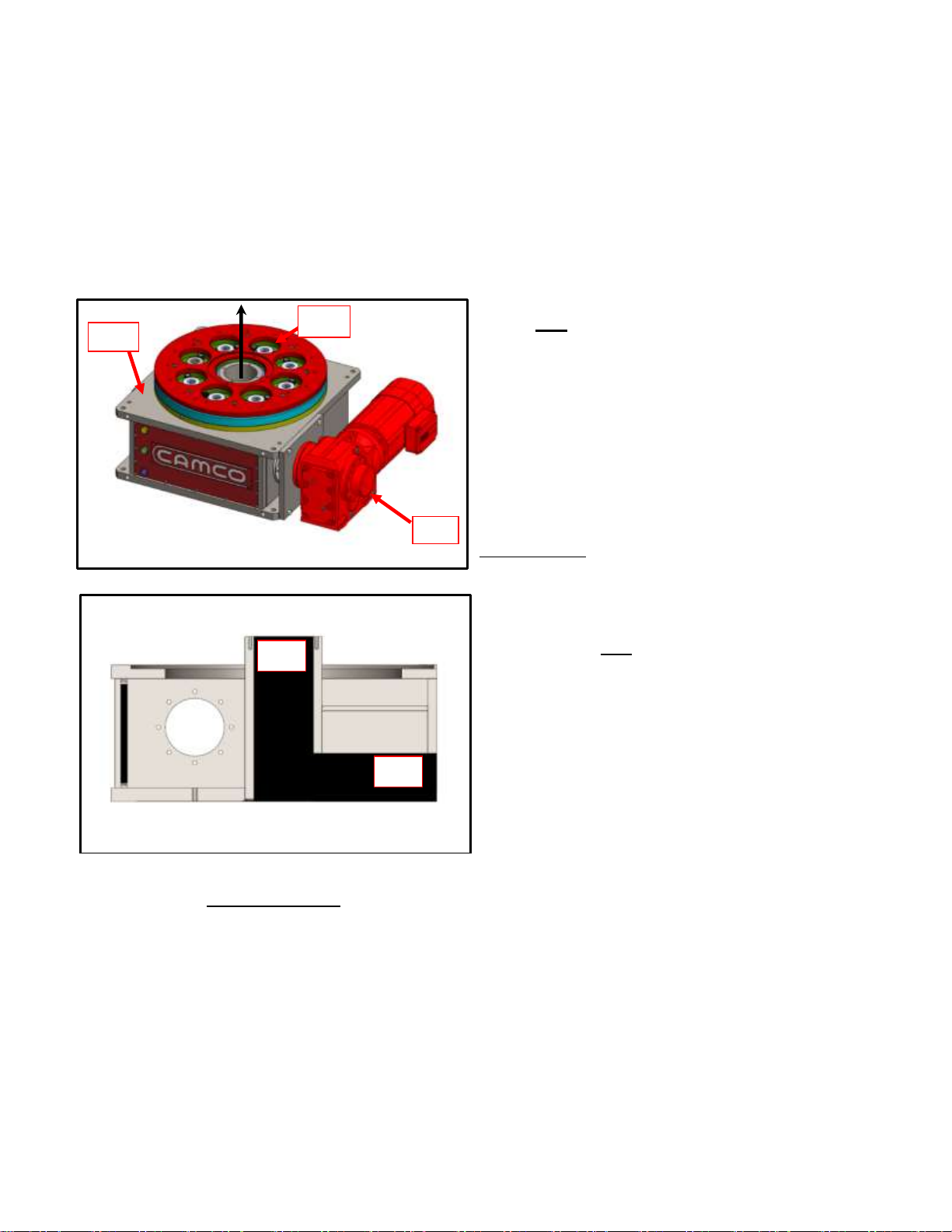
General view of the machine
The unit consists of the
following main components
(FIGURE 1)
01. Housing: Machined Housing
Weldment, Cover Plate
02. Output Assembly: Follower-
Wheel, Dial Plate, Output bearing
03. Input Assembly: Cam, Cam-
Shaft, Reducer Mounting plate,
Gear motor with brake.
Figure 1 Unit
04. Center-Bore: Allows passage
of wires, robotics and various
tooling through unit.
05. Allows for Table-Top or
Trunnion (optional) mounting with
mounting holes placed on front
and bottom faces of housing.
01
02
01
03
02
Figure 2 Access

13
Presentation
and
identification
Identification of the machine
The following information can be found on the machine rating plate:
Company name with full address
DE-STA-CO CAMCO PRODUCTS
1444 SOUTH WOLF ROAD
WHEELING, ILLINOIS 60090 USA
Article No.: MDE600M : MDE700M : MDE900M
Year of construction: 2015
4.2 Intended Use
Intended
use
The machine has been built within the battery limits to the state-of-the-art and in
accordance with the acknowledged general safety engineering rules. Nevertheless
hazards can arise during its use for the life and limb of the operator or third parties and for
impairment to the machine and other assets.
The machine may only be operated for its intended when it is in a technically safe
condition, giving consideration to safety and the potential hazards, in accordance with the
operating manual! Have all malfunctions remedied immediately, in particular those which
could impair safety.
The machine is intended exclusively for the purpose described in chapter 4.5 "Description
of function". Any other or further use constitutes an improper use. The
MDE600M-04-ND1-A-B-1-E
MDE: MODEL FAMILY (MDE SERIES)
600: MODEL DIAL SIZE (600mm)
M: MODEL TYPE (MECHANICAL)
04: MODEL MOTION (NUMBER OF STOPS)
ND1: MODEL GEAR-MOTOR (NORD GEAR-MOTOR 1)
A: GEAR-MOTOR RATIO OPTION (RATIO-A)
B: GEAR-MOTOR BRAKE OPTION (BRAKE-B)
1: GEAR-MOTOR MOUNT SIDE (SIDE-1)
E: MODEL SENSOR OPTION (SENSOR-E)

14
Intended
use
manufacturer/supplier assumes no liability for injury or damage resulting from such use.
This risk must be borne solely by the owner.
The intended use also includes observance of the operating
manual and compliance with the inspection and maintenance
conditions.
4.3 Foreseeable Improper Use
Foreseeable
improper use
Any use, setting, application or alteration of the unit beyond the stated terms in
section 4.5 is defined as improper and prohibited.

15
4.4 Design and Components of the Machine
Front and Top View
A

16
Section and Side View

17
Bill Of Materials
MDE Bill Of Materials
ITEM
DESCRIPTION
QTY
1
HOUSING
1
2
HOUSING COVER
1
4
BREATHER
1
5
DRAIN PLUG
1
6
SIGHT GLASS
1
7
CAM SHAFT
1
8
CAM-MDE
1
9
INPUT CARTRIDGE
2
12
OIL SEAL INPUT
2
28
LUBE NIPPLE
2
29
FOLLOWER WHEEL
1
30
CAM FOLLOWER
v
32
FOLLOWER CARTRIDGE
v
33
ROUND CLAMP
v
35
V-SEAL
1
36
DIAL PLATE MOUNT
1
39
PROXIMITY/SENSOR SWITCH BRACKET
v
41
PROXIMITY/SENSOR SWITCH
v
4.5 Description of Function
The Mechanical MDE Series Indexer is a pre-loaded-right-angle indexing table
designed to precisely move heavy loads at a predetermined number of stations with
zero-backlash. This machine is exactly defined as incompleted machinery that has
no specific function / output until incorporated into a complete machine.
Description of
function
4.6 Places of Work of the Operating Personnel
The Mechanical MDE Series Indexer is designed for integration into complete
machines. Safe operation and control are the responsibility of the machine builder
and the machine operator.
Places of
work of the
operating
personnel

18
4.7 Hazard Zones
Hazard zones
Hazardous zones of the machine may only be entered by designated and authorised
persons!
If several persons are working on the machine, good cooperation and close
coordination of the activities is necessary.
Electrical energy
a) Use only original fuses with the prescribed amperage! In the event of faults in
the electric power supply, switch off the machine immediately!
b) Work on electrical installations or equipment may only be carried out by an
electrician or by trained persons under the instruction and supervision of an
electrician.
c) Parts of machines and installations on which inspection, maintenance and
repair work is being carried out on the electrical equipment must –if prescribed
–be isolated and secured to prevent restarting. First check that the isolated
parts are no longer live, then earth and short-circuit and isolate adjacent live
parts
d) The electrical equipment of the machine must be inspected and checked at
regular intervals. Faults such as loose connections or scorched cables must be
remedied immediately.
e) If work is necessary on live parts, have a second person standing by who can
turn off the master switch or emergency stop switch in the event of an
emergency. Cordon off the working area with a red/white safety chain and a
warning sign. Use only insulated tools and equipment!
f) When working on high-voltage assemblies, switch off the power supply, connect
the supply cable to earth and short-circuit the components, e.g. capacitors, with
a ground rod.

19
Hazard zones
Hydraulic/pneumatics
a) Work on this equipment may only be carried out by persons with specialist
know-how and experience!
b) Inspect all lines, hoses and screw fittings at regular intervals for leaks and
obvious signs of damage! Repair damage immediately! Escaping oil can lead to
injuries and fires.
c) Depressurise system sections and pressure lines to be opened in accordance
with the descriptions of the assemblies before starting the repair work!
d) Lay and install hydraulic and compressed air lines correctly! Do not confuse
connections. Fittings, lengths and qualities of the hoses must comply with the
requirements.
Noise
a) Soundproofing installations on the machine must be functional during operation.
b) Wear the prescribed personal protective equipment (ear protectors)!
Oils, greases and other chemical substances
a) Process media must be used and disposed of in accordance with the instruction
of the manufacturers of these substances.
b) Pay particular attention with hot process media (risk of burns and scalding)!
This manual suits for next models
3
Table of contents
Popular DC Drive manuals by other brands

Vacon
Vacon 100 INDUSTRIAL user manual

Allen-Bradley
Allen-Bradley PowerFlex 6000 installation instructions

TIME LED
TIME LED 781234 Installation and operating instructions

INVT
INVT 0R7G-4 Operation manual

Siemens
Siemens SINAMICS PERFECT HARMONY GH180 Function manual

ABB
ABB ACQ580-01 Series Quick installation and start-up guide


HAUTAU
HAUTAU SVA 18 v Mounting instructions

TRENDnet
TRENDnet TE100-PCBUSR - DATA SHEETS Quick installation guide

Aquagem
Aquagem iSAVER Power+1100 Installation & user guide

Hytronik
Hytronik HED1050L instruction manual

Iomega
Iomega Zip 750MB Quick install

motortronics
motortronics VMX-Synergy Plus ANSI quick start guide