Ambient daylight threshold [ ]
Press button , the latest surrounding lux value overwrites previous lux value learned, and is set as the daylight threshold. This feature enables the fixture
to function well in any environment.
Detection range[ ]
Press buttons in zoneto set detection range at 100% / 50% / 10%.
Hold time [ ]
Press buttons in zoneto set hold time at 30s / 1min / 5min / 10min / 30min.
Stand-by period [ ]
Press buttons in zone to set the stand-by period at 0s / 10s / 1min / 10min / 30min / +∞.
Note: “0s” means on/off control; “+∞” means bi-leve of dimming control, the light will never switch off.
(i.e. the light remains at the stand-by dimming level until motion is detected.)
Stand-by dimming level [ ]
Press buttons in zoneto set the stand-by dimming level at 10% / 20% / 30% .
Daylight sensor []
Press buttons in zone to set daylight sensor at 2lux / 10lux / 50lux.
10
6
Press button ,the sensor goes to manual override or semi-auto function.
15
11
13
12
7
button
10
Power output [ ]
Press button , the output shifts between 80% and 100%, for energy saving purposes.
5
button 5
Dim +/- [ ]
Press button to adjust the light brightness between 10%~100% during hold-time.“+” increases the light level, “-” will decrease the light level.
9
button 9
Lux disable [ ]
Press button , the built-in daylight sensor is disabled, the light will always operate upon detection regardless of ambient light level.
14
button
14
Manual override/ Semi-auto [ ]
Note: The buzzer beeps twice if it is in manual override mode, and beeps once if shifts to semi-auto mode.
button
15
zone 6
zone
11
zone
12
zone
7
zone 13
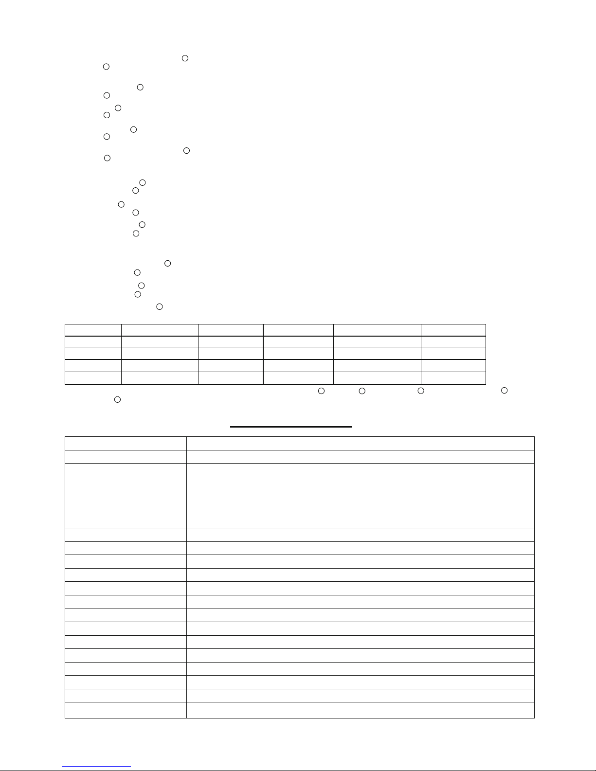
Scene mode options [ ]
Note: the end-user can fine tune the settings by pressing buttons of detection range / hold time / stand-by period / stand-by dimming level
/daylight sensor , the last setting will over-write that feature of the pre-set scene.
611
13
12
7
zone 4
There are 4 scene modes built into the remote control for different applications:
Scene options Detection range Hold time Stand-by period Stand-by dimming leve Daylight sensor
SC1 100% 1min 10min 10% 2Lux
SC2 100% 5min 10min 10% 2Lux
SC3 100% 10min 30min 10% 10Lux
SC4 100% 10min + 10% 50Lux
8
Mains voltage
Mains current
Power factor
Operation temperature
Dimming interface
Abnormal protection
Dimming range
Stand-by power consumption
Over-heat protection
EMC standard
Safety standard
DALI standard
Dielectric strength
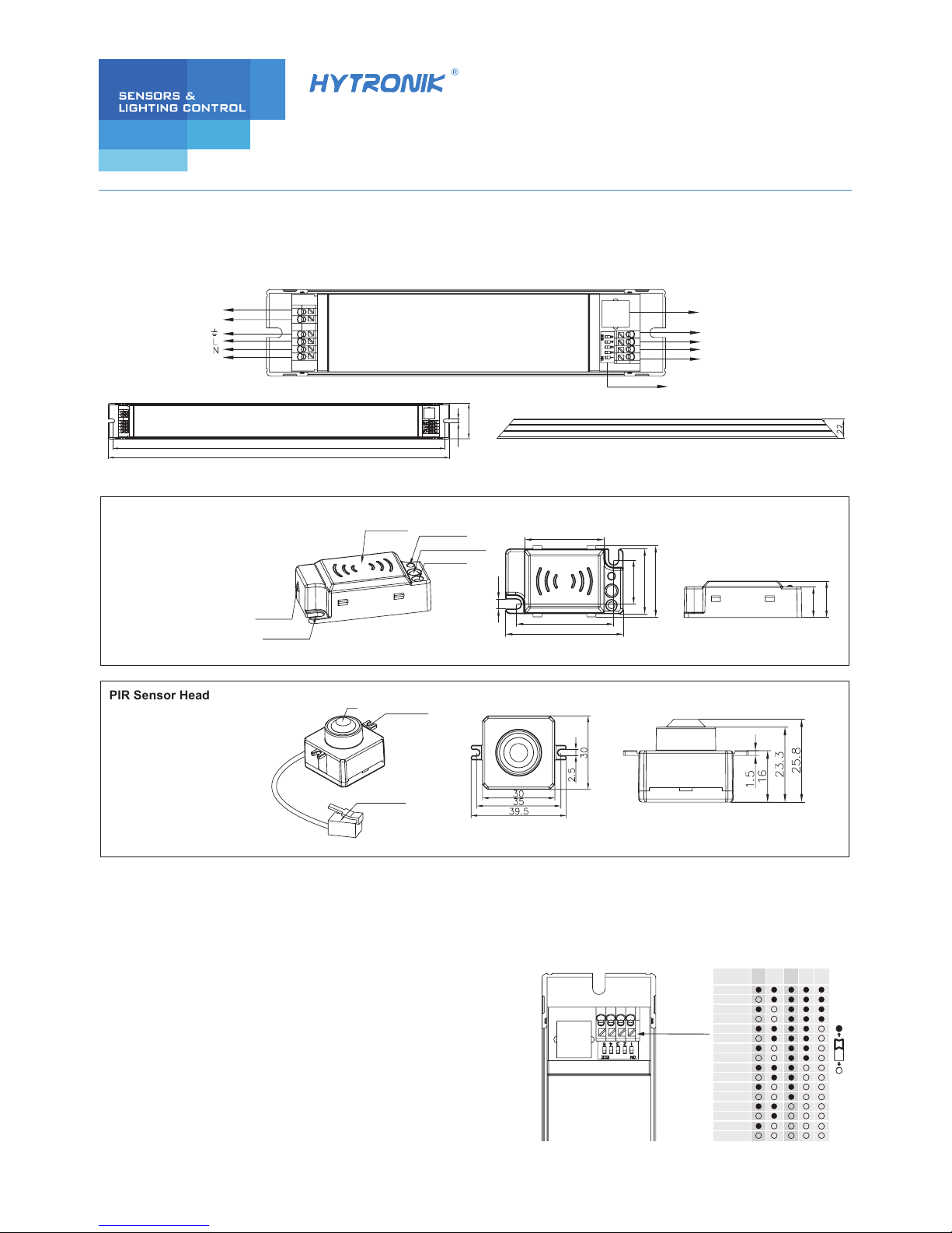
IP grade
220~240VAC 50/60Hz
≥0.96
Output voltage ( U-out max.) 200V
Ta: -20~+50℃Tc:+80℃
Output short-circuit protection with auto-reset
1~30% PWM dimming; 30~100% analogue dimming.
<0.5W
Over-heat protection with auto-reset
EN55015, EN61547, EN61000-3-2/3
EN61347-1, EN61347-2-13, EN60598-1
IEC62386-101,102,207
Input →output : 3750VAC
IP20
0.3 ~ 0.25A
34W / 225mA / 36 ~ 150V 38W / 250mA / 36 ~ 150V 41W /275mA / 36 ~ 150V
45W / 300mA / 36 ~ 150V 49W / 325mA / 36 ~ 150V 50W / 350mA / 36 ~ 140V
50W / 375mA / 36 ~ 130V 50W / 400mA / 36 ~ 125V 50W / 425mA / 36 ~ 115V
50W / 450mA / 36 ~ 110V 50W / 475mA / 36 ~ 105V 50W / 500mA / 36 ~ 100V
50W / 525mA / 36 ~ 95V
50W / 600mA / 36 ~ 83V
50W / 550mA / 36 ~ 90V 50W / 575mA / 36 ~ 86V
89%
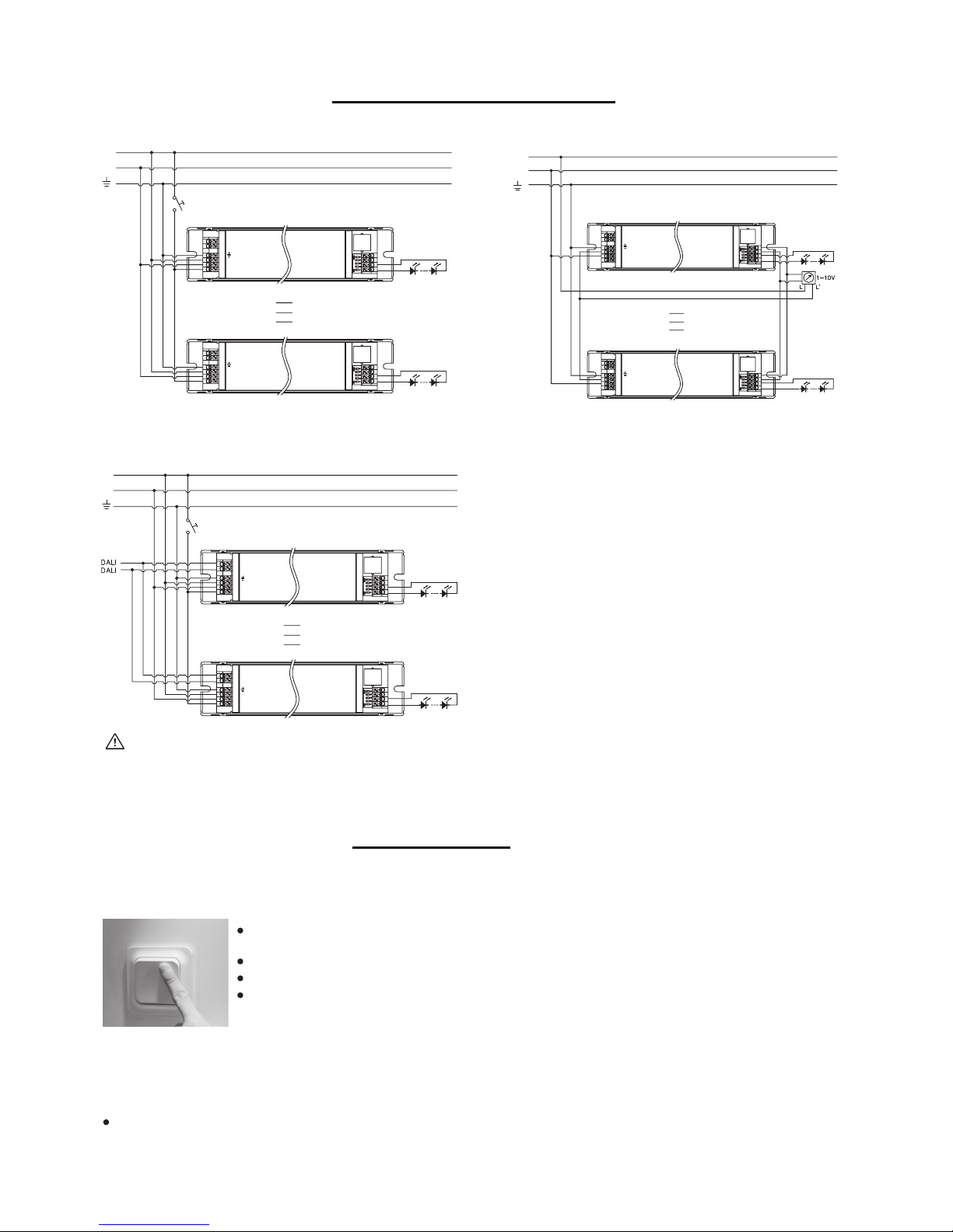
DALI, Switch-Dim., 1-10V
Max. output
power/current/voltage
Max. Efficiency
SECTION 4 SPECIFICATION