LIVI 500
Istruzioni d’uso ed avvertenze
5
conforme a quanto prescritto dalla normativa vigente.
Tutti i modelli di LIVI 500 sono dotati di un dispositivo di
sblocco; il funzionamento di tale dispositivo nei modelli della
serie 502 e 503 è il seguente. Una volta aperta la serratura
posta sulla maniglia (protetta dal coperchietto in plastica) la
leva va girata nel senso indicato in F9 pag. 32; a questo punto il
riduttore è sbloccato e il cancello, in assenza di altri impedimenti
è libero nei suoi movimenti. Il procedimento inverso, ruotare la
leva fino a fine corsa e chiusura della serratura (ricordarsi di
proteggere la serratura con l’apposito coperchietto), riporta LIVI
500 in condizioni di lavoro.
Nei modelli 500 e 501 il dispositivo di sblocco si attiva nel
seguente modo. Una volta aperta la serratura posta sul carter
(protetta dal coperchietto in plastica) togliere il carter e portare
la leva di sblocco in posizione 2 (vedi F9 pag. 32); a questo
punto il riduttore è sbloccato e il cancello, in assenza di altri im-
pedimenti è libero nei suoi movimenti. Il procedimento inverso,
portare la leva in posizione 1, assemblare il carter e chiusura
della serratura (ricordarsi di proteggere la serratura con l’appo-
sito coperchietto), riporta LIVI 500 in condizioni di lavoro.
Per tutti i modelli, nel caso in cui non sia possibile per qual-
siasi motivo l’accesso allo sblocco del riduttore, installare l’ac-
cessorio 560 M “Dispositivo di sblocco a filo” (vedi “ACCESSORI
PRODOTTO”) seguendo le istruzioni contenute nello stesso.
4.5.5. Regolazione
Per l’installazionedei prodottiserie 500e 502non sononecessarie
regolazioni; per l’installazione dei prodotti serie 501 e 503 l’uni-
ca regolazione necessaria è quella della posizione del finecorsa.
Tale regolazione viene effettuata svitando le viti di fissaggio
delle camme di chiusura ed apertura (vedi F4 pag. 30), ruotan-
do quest’ultime lungo il disco porta camme fino al raggiungi-
mento della posizione voluta e riavvitando le viti.
ATTENZIONE Altre operazioni di regolazione/taratura diver-
se dalla regolazione dei finecorsa sono eseguite dal produtto-
re. L’intervento su queste può causare malfunzionamento e/o
situazioni di pericolo per persone, animali e cose. Evitare ogni
intervento non autorizzato da DEA System.
4.5.6. Manutenzione e riparazione
Una buona manutenzione preventiva ed una regolare ispe-
zione al prodotto ne assicurano una lunga durata (vedi anche
“Garanzia”). In caso di guasto si può far riferimento alla tabella
“GUIDA RICERCA GUASTI” (vedi pagina 4) per cercare una
soluzione al problema; se i consigli riportati non portano alla
soluzione contattare DEA System.
Le operazioni di ispezione/manutenzione che sono da
programmare sul “registro di manutenzione dell’automazione
completa” sono:
TIPO DI INTERVENTO PERIODICITA’
pulizia superfici esterne 6 mesi
controllo serraggio viti 6 mesi
controllo funzionamento dello sblocco 6 mesi
ingrassaggio giunzioni 1 anno
ATTENZIONE Qualsiasi operazione d’installazione, manu-
tenzione, pulizia o riparazione dell’intero impianto devono
essere eseguite esclusivamente da personale qualificato;
operare sempre in mancanza di alimentazione e seguire scru-
polosamente tutte le norme vigenti nel paese in cui si effettua
l’installazione, in materia di impianti elettrici.
ATTENZIONE L’utilizzo di parti di ricambio non indicate da
DEA System e/o il riassemblaggio non corretto possono cau-
sare situazioni di pericolo per persone, animali e cose; pos-
sono inoltre causare malfunzionamenti al prodotto; utilizzare
sempre le parti indicate da DEA System e seguire le istruzioni
per l’assemblaggio.
4.6. Addestramento
Il funzionamento dell’automatismo completo, una volta
messo a punto dall’installatore, va attentamente illustrato al-
l’utente finale. E’ importante, per quanto riguarda LIVI 500,
istruire sul funzionamento dello sblocco (vedi “Allegati”) e su
quale sia il programma di manutenzione che lo riguarda (vedi
punto 4.5.6.).
ATTENZIONE La conoscenza del funzionamento dello sbloc-
co a chiave (vedi F9 pag. 32) di LIVI 500 è molto importante
per tutti gli utenti dell’automatismo in quanto, in momenti di
emergenza, la mancanza di tempestività nell’agire su tale di-
spositivo può causare situazioni di pericolo. L’allegato I delle
presenti istruzioni è una pagina staccabile che ne illustra il
funzionamento; l’installatore è tenuto a consegnarla all’utente
finale.
4.7. Controindicazioni di utilizzazione
Al capitolo “4.4 Condizioni di utilizzazione previste”sono
state descritte le condizioni per le quali il prodotto è stato pro-
gettato e testato. Non utilizzare il prodotto per scopi diversi.
ATTENZIONE L’utilizzo del prodotto in condizioni anomale
non previste dal costruttore può generare situazioni di perico-
lo; rispettare le condizioni previste dalle presenti istruzioni. A1
ATTENZIONE In nessun caso utilizzare il prodotto in presen-
za di atmosfera eplosiva. In nessun caso utilizzare il prodotto
in ambienti che possono essere agressivi e danneggiare parti
del prodotto.
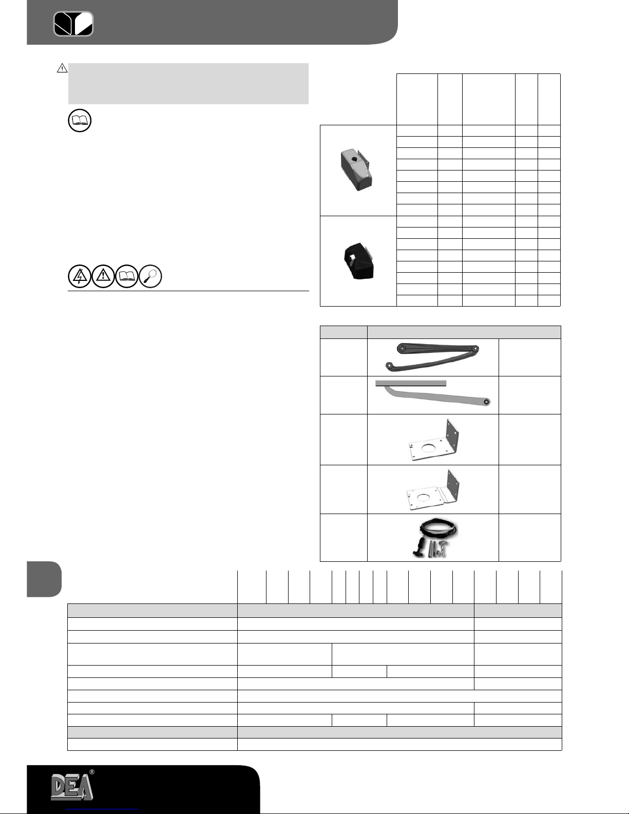
5 LISTA PARTI ORDINABILI
La lista delle parti ordinabili (pagg. 28, 29 e 33) è un detta-
gliato elenco che accompagna l’esploso del prodotto e che deve
essere utilizzata per l’ordine di parti di ricambio.
In tale documento va sempre indicato fra l’altro:
• il codice del prodotto (ricavabile dall’etichetta prodotto; vedi
F5 pag 30),
• il numero di posizione della parte nell’esploso,
• sedisponibile, può essere utile la datadiacquisto del prodotto.
6 ASSIEME COMPLETO CHIUSURA
Questo capitolo, che illustra un’installazione tipo di un au-
tomatismo completo, viene redatto con lo scopo di informare
ed agevolare l’installatore nella scelta dei vari componenti nel
rispetto della Direttiva Macchine (98/37/CE) e delle Normative
Europee riguardanti la sicurezza (EN 12453 - EN 12445) per
l’installazione dei cancelli.
I dati riportati in questo capitolo non hanno lo scopo di essere
completi ed esaurienti. DEA System non può assumersi alcuna
responsabilità per eventuali errori, omissioni o approssimazioni.
6.1 Protezione del bordo principale
Tra i rischi più rilevanti che sono da considerare nell’auto-
mazione di un cancello ad anta battente vi è quello di schiac-
ciamento tra le due ante in chiusura, o tra di un’anta e la sua
battuta. Le norme citate prevedono che, per tale rischio, sia
adottata un’appropriata tipologia di comando di attivazione in
funzione della tipologia d’uso a cui il cancello è destinato (vedi
tabella “COMANDO DI ATTIVAZIONE”).
6.2 Schiacciamento nell’area di apertura
Possibile rischio di schiacciamento c’è nella zona che sta tra
il cancello in apertura e tipicamente un muro di recinzione od
altro ingombro. In F10 pag. 32 sono riportate le misure che
è necessario rispettare nel caso in qui non si ricorra alla limi-
tazione delle forze di impatto o a sistemi di rilevazione della
presenza.
6.3 Impatto nell’area di chiusura o di apertura
Per evitare l’impatto di persone con l’anta nell’area di chiu-