decrane aerospace MAP-9101-10 Series User manual
7300 Industry Drive, North Little Rock, AR 72117
Phone: 501-955-2929 Fax: 501-955-2988
www.decraneaerospace.com
Installation Manual
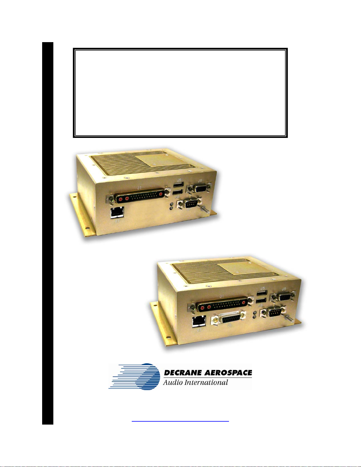
MAP-9101-10x-x
Moving Maps Server
Document # 540372
MAP-9101-100-x
MAP-9101-101-x

DeCrane Aerospace Audio International MAP-9101-10x-x Installation Manual
Document # 540372, Rev IR, 12/2008 Page 1 of 29
Document Revision History
Rev. Le
vel
Date
Description
IR 12/2008 Initial Release
Reference Documents
(or latest revision)
Document #
Description
526167 Rev B MAP-9101-100-x Outline Drawing
526371 Rev IR MAP-9101-101-x Outline Drawing
Service Bulletin List
Service
Bulletin # Subject
Manual
Revision
Revision
Date
Table of Illustrations
Section #
Description
Page #
2.1 Block Diagram – Typical Application 5
7.0 Reference Drawings 22
PROPRIETARY INFORMATION NOTICE: Despite any other copyright notice, this document and
information disclosed herein contains confidential, proprietary designs owned by DeCrane
Aerospace Audio International. Neither this document nor the data contained herein shall be
reproduced, used or disclosed to anyone without the written authorization of DeCrane
Aerospace Audio International.

DeCrane Aerospace Audio International MAP-9101-10x-x Installation Manual
Document # 540372, Rev IR, 12/2008 Page 2 of 29
Table of Contents
Section Description Page
1.0
General Information
. . . . . . . . . . . . . . . . . . . . . . . . . . . . .
3
1.1 Introduction . . . . . . . . . . . . . . . . . . . . . . . . . . . . . . . . . . . . .
3
1.2 Purpose of the Equipment . . . . . . . . . . . . . . . . . . . . . . . . . .
3
1.3 Optional Equipment . . . . . . . . . . . . . . . . . . . . . . . . . . . . . . .
4
2.0
Application
. . . . . . . . . . . . . . . . . . . . . . . . . . . . . . . . . . . . .
5
2.1 Block Diagram – Typical Applications . . . . . . . . . . . . . . . . .
5
2.2 Typical Equipment Interfaces . . . . . . . . . . . . . . . . . . . . . . . 5
2.3 Additional Interfaces . . . . . . . . . . . . . . . . . . . . . . . . . . . . . .
6
3.0
Installation . . . . . . . . . . . . . . . . .
. . . . . . . . . . . . . . . . . . . .
8
3.1 Prior to Installation . . . . . . . . . . . . . . . . . . . . . . . . . . . . . . . .
8
3.2 Unpacking and Inspection . . . . . . . . . . . . . . . . . . . . . . . . . .
8
3.3 Cautions &Warnings . . . . . . . . . . . . . . . . . . . . . . . . . . . . . .
9
3.4 Wiring Requirements . . . . . . . . . . . . . . . . . . . . . . . . . . . . . .
10
3.5 Updating Logo File . . . . . . . . . . . . . . . . . . . . . . . . . . . . . . . 11
3.6 Updating Audio Briefings . . . . . . . . . . . . . . . . . . . . . . . . . . .
12
3.7 Electrical Characteristics . . . . . . . . . . . . . . . . . . . . . . . . . . .
16
3.8 Mating Connector Information . . . . . . . . . . . . . . . . . . . . . . .
17
3.9 Pinout Assignment Descriptions . . . . . . . . . . . . . . . . . . . . .
20
3.10
Post-Installation Test . . . . . . . . . . . . . . . . . . . . . . . . . . . . . .
24
4.0
Instructions for Continued Airworthiness . . . . . . . . . . .
24
5.0
General Troubleshooting Procedures . . . . . . . . . . . . . . .
2
4
6.0
Specifications . . . . . . . . . . . . . . . . . . . . . . . . . . . . . . . . . .
25
7.0
Reference Drawings . . . . . . . . . . . . . . . . . . . . . . . . . . . . .
2
6
7.1 MAP-9101-100-x’s Reference Drawings. . . . . . . . . . . . . . . 26
7.2 MAP-9101-101-x’s Reference Drawings. . . . . . . . . . . . . . . 28

DeCrane Aerospace Audio International MAP-9101-10x-x Installation Manual
Document # 540372, Rev IR, 12/2008 Page 3 of 29
MAP-9101-10x-x
Moving Maps Server
1.0 General Information
1.1 Introduction
This manual contains information for the proper application and installation
of the DeCrane Aerospace Audio International (DAAI) server, Model
No: MAP-9101-10x-x. The MAP-9101-10x-x is a Moving Map Server with
a Single Compact Flash Hard Disk Drive and the ability to display the end
user’s customized logo. The “x” in the “-10x” designates the differences
between units. The MAP-9101-101-x can be used to navigate and control
the interactive map screens and audio briefings (initiated via discrete
inputs and/or data bus commands). The MAP-9101-100-x does not have
interactive map screens or audio briefings. The “-x” suffix in both models
designates the type of connector utilized; “-1” = Positronic and “-2” = D-
Subminiature. Also included are physical, mechanical, and electrical
characteristics of the unit.
1.2 Purpose of the Equipment
The MAP-9101-10x-x Onboard Server Module provides support for
interactive and non-interactive moving maps via local video outputs and to
remote client devices. It also contains circuitry to support special purpose
applications such as HTTP Server, and Digital Media Audio Briefings.
The MAP-9101-10x-x provides the following key features:
Motherboard (not all functions are necessarily used)
•1.0GHz ULV Celeron M 373 Processor
•Up to 512kB Level 2 Cach
•Up to 1GB DDR SODIMM
oSupports a single +2.5V DDR RAM SODIMM
oSupports PC2700 DDR 333 (166MHz)
•Frontside Bus @ 400MHz
•AGP 128-bit 3D video interface with built-in dual-channel LVDS
•Dual PCI-bus Enhanced Ultra DMA 33/66/100 Synchronous IDE
interface supports up to four storage devices
•(2) Serial TTL Level Interface
•Single IrDA 1.1 Infrared Interface
•(4) USB 2.0
•AC97 CODEC for Audio Interface

DeCrane Aerospace Audio International MAP-9101-10x-x Installation Manual
Document # 540372, Rev IR, 12/2008 Page 4 of 29
•10/100 BaseT Ethernet interface
•Watchdog Timer
•Real-Time Clock
•Customizable Splash Screen for OEM boot logo
•Configuration EEPROM – 512 Bits
Data / Interface / Configuration Ports
•Dual 10/100Base-T Ethernet Interfaces
oFull-Duplex
oHalf-Duplex
oIEEE 802.3x Flow Control in Full-Duplex Mode
oAuto-Negotiation for Speed, Duplex Mode, and Flow Control
•Serial Ports
oRS-232
oRS-485 for AI Standard Data Bus
oARINC 429 Receiver for Flight Management System (FMS)
Interface (x2)
•USB – Two (2) USB 2.0 Ports
•16 Gigabyte Industrial Grade Compact Flash
Video
•Composite NTSC Video Output
•SMPTE-259 SDI Video Output
•SVGA Video Output
Audio - MAP-9101-101-x Model Only
•Two (2) mono Analog Briefer Audio Outputs – 2Vrms
oBoth Outputs Play the Same Briefer
oBriefer Pause Discrete Input
oBriefer Active Key Output
•Audio Briefings
oUp to 100
1.3 Optional Equipment
DeCrane Aerospace Audio International offers a comprehensive family of
Cabin Control Modules for PC interfaces. These modules provide
convenient solutions for a variety of frequently encountered interfacing
needs or special requirements and are an important part of DAAI’s
“building block” system for configuring total cabin management.
Contact your DAAI representative for details.
DeCrane Aerospace Audio International MAP-9101-10x-x Installation Manual
Document # 540372, Rev IR, 12/2008 Page 5 of 29
2.0 Application
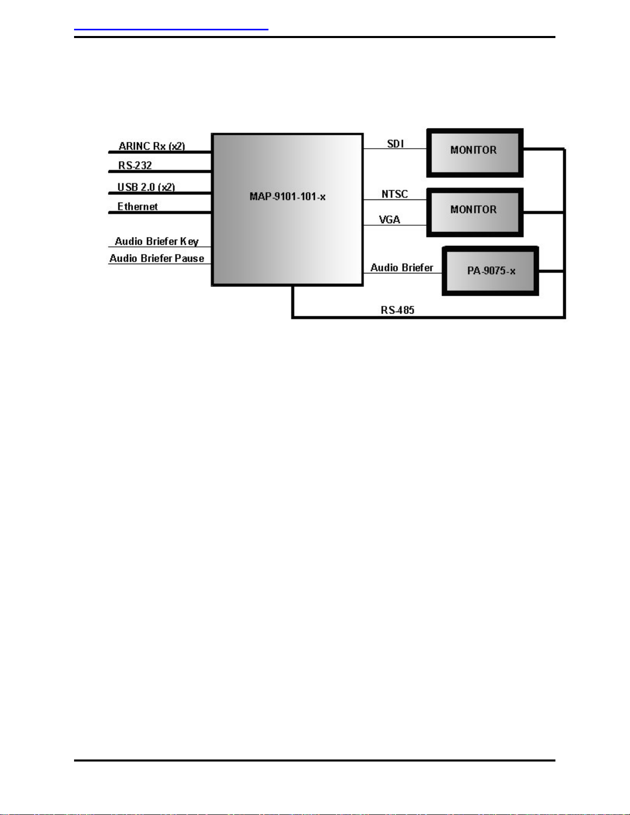
2.1 Block Diagram – Typical Application
* Only available for model MAP-9101-101-x.
2.2 Typical Equipment Interfaces
2.2.1 Video Output (SVGA, NTSC Analog, and SDI)
Typical interfaces include various video distribution and/or signal
manipulation devices. The unit is capable of interfacing and
providing output to all DeCrane Aerospace Audio International and
standard COTS (Commercial-Off-The-Shelf) video devices and/or
equipment.
2.2.2 Briefer Audio Output (Mono Analog)
This interface is only available for model MAP-9101-101-x. Typical
interfaces include various audio distribution and/or signal
manipulation devices. The unit is capable of interfacing and
providing output to all DeCrane Aerospace Audio International and
standard COTS audio devices and/or equipment. Two outputs of
the same signal are provided for connection to multiple devices.
S
*
*
*
*

DeCrane Aerospace Audio International MAP-9101-10x-x Installation Manual
Document # 540372, Rev IR, 12/2008 Page 6 of 29
2.3. Additional Interfaces
2.3.1 Audio Interface
This interface is only available for model MAP-9101-101-x. This unit
provides for the routing of the audio briefer to two (2) audio briefer
outputs to allow routing of the briefer to two separate locations.
Analog Audio Outputs
Output Level:2.0Vrms
2.3.2 Video Interfaces
This unit provides for four (4) independent video outputs: One (1)
SVGA Video, one (1) NTSC Video, and two (2) SDI-Video.
SVGA Video Output
Industry standard SVGA video output in 800x600 resolution
NTSC Video Output
Output Level: 1.0 Vp-p
Output Impedance: 75-ohm
Video Formats: NTSC
SDI-Video Output
Serial Digital Video in SMPTE 259M format.
2.3.3 Infrared Interface
Infrared interfaces are optional for this unit.
Functionality relating to possible infrared capability is interfaced via
one of the provided data communication interfaces.
2.3.4 Discrete Interface(s)
This unit provides for two (2) discrete interfaces. The discrete
output (GND active) actives the primary audio briefer. The discrete
input (GND active) is used to pause the briefer.

DeCrane Aerospace Audio International MAP-9101-10x-x Installation Manual
Document # 540372, Rev IR, 12/2008 Page 7 of 29
2.3.5 Data Communication Interface(s)
2.3.5.1 RS-232 (Serial Port)
This unit incorporates one (1) RS-232 serial data bus
interface for general purpose communication to external
devices. Full hardware handshaking capability is provided.
2.3.5.2 ARINC 429
This unit incorporates two (2) individual and isolated
receive-only ARINC 429 serial data bus interfaces to
obtain flight-specific information provided via an aircraft-
integrated flight management system (FMS). Each
interface goes to a common program and is set for low
speed. Although it can be set for high speed, both inputs
must be the same speed. Each interface is configurable
for either a high-speed (100 Kbps) or a low-speed
(12.5 Kbps) data rate.
2.3.5.3 RS-485 (Standard)
This unit incorporates one (1) RS-485 serial data bus
interface for communication purposes to other DeCrane
Aerospace Audio International RS-485 network-connected
devices. All RS-485 serial data bus electronic interface
parameters are compliant to AI document #640071.
2.3.5.4 10/100Base-T Ethernet
This unit incorporates one (1) Intel 82551QM (10/100
Base-T) Ethernet network interface for communication
purposes to other network-connected devices. The
Ethernet interface is compliant to IEEE 802.3
specifications and requirements.
2.3.5.5 USB 2.0
This unit incorporates two (2) USB 2.0 interfaces (2 root
hubs, J5 and J6 connectors).
The Logo File can be updated to display the end user’s
customized logo by loading the file through either of the
USB connections, see Section 3.5 for instructions.

DeCrane Aerospace Audio International MAP-9101-10x-x Installation Manual
Document # 540372, Rev IR, 12/2008 Page 8 of 29
Only model MAP-9101-101-x’s can be used to connect a
USB mouse connection for map control. Either USB port
will accept the mouse connection.
3.0 Installation
3.1 Prior to Installation
3.1.1 During the design and layout of the aircraft cabin, careful
consideration of the location of the MAP-9101-10x-x is necessary.
Some of the items to be considered include:
•Space
•Proximity to other devices (i.e. source equipment)
•Available power supply
•Length of cable runs
•Environmental conditions (temperature, humidity, etc.)
•Location of other aircraft systems (i.e. oxygen delivery)
•Access for service repair (if applicable)
3.1.2 The MAP-9101-10x-x shall be installed to conform to the standards
designated by the customer, installing agency, and existing
conditions as to the unit location and type of installation.
3.1.3 Mounting provisions are provided via four (4) 0.187-inch diameter
mounting holes – two (2) on each side of unit on provided mounting
flanges. Refer to Section 7.0, Reference Drawings, for mounting
hole diameters and configuration.
3.1.4 The unit is capable of installation/mounting in any orientation
whether horizontal, vertical, inverted, or at an angle.
3.1.5 An internal fan exhausts heat from the unit. Proper ventilation must
be allowed for when specifying the installation location. The
closeout area of the monitor shall have a clearance of 2 inches
(5.08 cm) minimum for the air inlet and exit areas. The closeout
area of the monitor case shall not block the air inlet or exhaust
openings of the monitor case. The fan will only run when the unit is
turned on.
3.1.6 Installation requires 2-inch spacing from other equipment, modules,
and structures except the mounting surface for which the unit
should be in direct contact.

DeCrane Aerospace Audio International MAP-9101-10x-x Installation Manual
Document # 540372, Rev IR, 12/2008 Page 9 of 29
3.2 Unpacking and Inspection
3.2.1 Carefully open the packaging and remove the unit. Verify that all
components have been included in the package per the packing
list. Inspect the unit for damage. Retain the packing materials and
packing list.
3.2.2 If damage has occurred during shipping, a claim should be filed
with DeCrane Aerospace Audio International WITHIN 24 hours and
a Return Request Authorization Number shall be obtained from
DAAI by contacting the Repair Department at 501.801.8101.
Repackage the unit in its original packaging materials and return it
to DAAI following instructions given by the DAAI representative.
Refer to the front cover of this manual for address. If no return is
necessary, retain the packing list and the packing materials for
storage.
3.3 Cautions and Warnings
3.3.1 It is important to do a pin-to-pin power and ground check on all
connectors. Ensure that power and ground are applied only where
specified. Damage to the unit may result if power or ground is
applied to the wrong points.
3.3.2 DO NOT connect or disconnect the module while power is applied.
3.3.3 DO NOT remove any factory-installed screws. Damage to the unit
may result and void any warranties.
3.3.4 No periodic scheduled maintenance or calibration is required for
continued airworthiness of the MAP-9101-10x-x. If the unit fails to
perform to specifications, it must be removed and serviced by a
qualified service facility.
3.3.5 ESD (Electro Static Discharge) guidelines shall be followed.
3.3.6 The chassis material and structural design of the unit is such that
the unit is not capable of containing fire and/or flames within the
unit.

DeCrane Aerospace Audio International MAP-9101-10x-x Installation Manual
Document # 540372, Rev IR, 12/2008 Page 10 of 29
3.3.7 The chassis material and structural design of the unit is such that
the unit is not capable of waterproof operation. Additionally, the
unit provides no specific or special provisions for fluid penetration
resistance to internal electronic components and/or assemblies.
3.4 Wiring Requirements
2.4.1 Introduction
The installing agency must supply and fabricate all external cables
and mating connectors. The length and routing of external cables
must be carefully studied and planned before attempting installation
of the equipment. Allow adequate space for installation of cable and
connectors. Avoid sharp bends and placing cables near aircraft
control cables. Maintain a minimum clearance of three (3) inches
from any control cable. If wiring is run parallel to combustible fluid
or oxygen lines, maintain a separation of six (6) inches between the
lines.
3.4.2 Power Wires
DeCrane Aerospace Audio International recommends that the
chassis be electrically bonded to the airframe structure by the
grounding lug with <0.1 resistance using <50 impedance
cable. Power and Ground wires shall be in accordance with
M22759 or equivalent. Protect power wires with circuit breakers or
fuses located close to the electrical power source bus.
3.4.3 Single Signal Wires
All single signal connections are recommended to use 22 AWG
(minimum) in accordance with NEMA WC 27500 or equivalent.
3.4.4 Multiple and/or Differential Signal Connections
All multiple and/or differential signal connections (i.e., analog audio,
RS-485 data bus communication, etc) are recommended to use 22
AWG (minimum) shielded twisted pair or shielded three-conductor
as necessary in accordance with NEMA WC 27500 or equivalent.
3.4.5 Analog Composite Video Connections
All analog composite video connections are recommended to use
shielded coaxial cable in accordance with M17/94-RG179 or
equivalent.

DeCrane Aerospace Audio International MAP-9101-10x-x Installation Manual
Document # 540372, Rev IR, 12/2008 Page 11 of 29
3.4.6 Composite and SDI Video Connections
Composite and SDI video connections are recommended to use
shielded coaxial cable in accordance with PIC V76261 or
equivalent.
3.4.7 SVGA wiring shall be in accordance with NEMA WC 27500 or
equivalent.
3.4.8 USB Connections
USB connections are recommended to use shielded twisted pair in
accordance with PIC USB2422 or equivalent.
3.4.9 10/100Base-TX Ethernet network connections
All 10/100Base-TX Ethernet network connections are
recommended to use shielded Category 5e equivalent Ethernet
cabling compatible with aircraft environments. Either a 4-conductor
or 8-conductor cable may be utilized. Each conductor shall be
stranded with an overall conductor gauge of 24 AWG, MINIMUM.
Overall conductor diameter (including jacket) shall conform to
mating connector requirements. Ethernet connections shall conform
to EIA/TIA 568 standards. PIC Wire & Cable P/N: E10424
(4-conductor) or E50824 (8-conductor) or equivalent cabling is
recommended for 10/100Base-T Ethernet cabling requirements.
Cable capable of supporting a minimum sustained data
communication rate of 100 Mbps is required.
3.5 Updating Logo File
This device has the ability to automatically upgrade the logo file that is
displayed on the logo page to allow an end user to install their custom
logo. The procedure to do this requires use of the USB flash drive that
comes with the unit or an equivalent compatible USB flash drive. The logo
file must be in GIF format with a resolution of 800 x 600. The file must be
named logo.gif in lower case letters. This file must be stored on the USB
flash drive in a directory named “logo” in lower case letters.
For example, if the flash drive appears as drive F: when inserted in a
laptop, the directory and file name would appear as “F:\logo\logo.gif”. The
directory letter may be different on the computer that is used to copy the
logo.gif file to the flash drive.
When the map server is active, insert the USB flash drive into either of the
USB drives (J5 or J6 connector). The map server will automatically
recognize the insertion of the flash drive and will copy the logo.gif file from

DeCrane Aerospace Audio International MAP-9101-10x-x Installation Manual
Document # 540372, Rev IR, 12/2008 Page 12 of 29
the \logo\ directory. The map server will automatically reboot after the file
is copied. During the boot process, the USB flash drive must be removed.
If the USB flash drive is not removed during the reboot process, the Map
Server will continue to reboot as it recognizes the drive after start up and
recopies the logo file.
3.6 Updating Audio Briefings
3.6.1 Installing Audio Briefings
Equipment required:
•Laptop computer
•Ethernet cross over cable
Software required:
•An SFTP over SSH2 client. (Recommended: Filezilla version
2.2.4 or later, A.I. part number 14500102 or available from
http://filezilla-project.org/)
•A text editor
3.6.2 Playlist Creation
Prepare all audio files that will be used for briefings. Since the
playlists are case sensitive it is recommended that lower case be
used exclusively for audio file names. However, as long as the
playlist contains the exact case, no problems will result from mixed
case.
Each playlist is a standard text file and can be created using
Notepad or any other text editor. Microsoft Word or other word
processing software is not acceptable since documents created by
them will contain non-visible control characters.
A playlist can contain one or more audio file names listed in the
order to be played. These files will be concatenated with no space
between them during play. For example, if you have three files
named greeting.mp3, takeoff.mp3 and close.mp3 that you
desire to play in sequence then the playlist will have the following
structure:
greeting.mp3
takeoff.mp3
close.mp3

DeCrane Aerospace Audio International MAP-9101-10x-x Installation Manual
Document # 540372, Rev IR, 12/2008 Page 13 of 29
Playlist files must have specific names in order for the control
software to locate and play them when they are triggered by an
external command. The file name also contains a number which is
used to select that list. There can be up to 100 playlists on the
server. A playlist filename always starts with the characters “pl” in
lower case followed by the two digit playlist number and terminated
with “.m3u”, exactly as shown.
For example:
Playlist number Filename
0 pl00.m3u
1 pl01.m3u
15 pl15.m3u
Playlists that are not named according to this convention will not be
playable by the control software.
3.6.3 Loading Files onto Server
Once the audio files and playlists have been created, they can be
loaded onto the server as indicated in the following procedure:
1. Configure the laptop to access the server. The IP address of the
laptop must be configured for the same subnet as the server in
order to make connection. Manually configure the laptop IP
address to 10.0.0.20/22
2. Attach the crossover cable to the laptop and the server.
3. Start the SFTP over SSH2 client software.
Enter the user name, password and Server IP address as
indicated below:
Name: root
Password: lazy8ball
IP address: 10.0.0.1
Note: Filezilla setup is as indicated in the example below:
(It is highly recommended that you use Filezilla)
4. Using the SFTP software, copy the audio files into the server
directory “/data/mpd/audio” directory and the playlists into the
“/data/mpd/playlist” directory.
5. Close the SFTP software, disconnect from the server and
restart the map server.
6. Installation is complete.
DeCrane Aerospace Audio International MAP-9101-10x-x Installation Manual
Document # 540372, Rev IR, 12/2008 Page 14 of 29
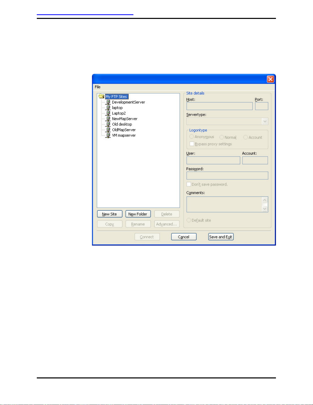
3.6.4 Setup for Filezilla
To setup Filezilla and establish a connection, start Filezilla and
press Ctrl+S to open the site manager. You will see a screen
similar to the one shown below.
Select “New Site” and enter the following information in the proper
boxes:
Host: 10.0.0.1
Servertype: select “SFTP over SSH2”
User: root
Password: lazy8ball
Press the “Connect” button. If the connection is successful, you will
be able to see the server file structure appear on the right center
portion of the screen. The left center portion of the screen contains
the file system of the laptop. On the left side, navigate to the folder
that contains your audio and playlist files. On the right side navigate
to the folder as shown in step 4 of the loading procedure above.
(Note: Double click on the “..” folder to move up a level. The right
side starts in the root user’s folder, you have to move up one level
first in order to get to the drive’s root directory.)

DeCrane Aerospace Audio International MAP-9101-10x-x Installation Manual
Document # 540372, Rev IR, 12/2008 Page 15 of 29
Select the desired files on the left side, then drag and drop them
into the proper directory on the right.

DeCrane Aerospace Audio International MAP-9101-10x-x Installation Manual
Document # 540372, Rev IR, 12/2008 Page 16 of 29
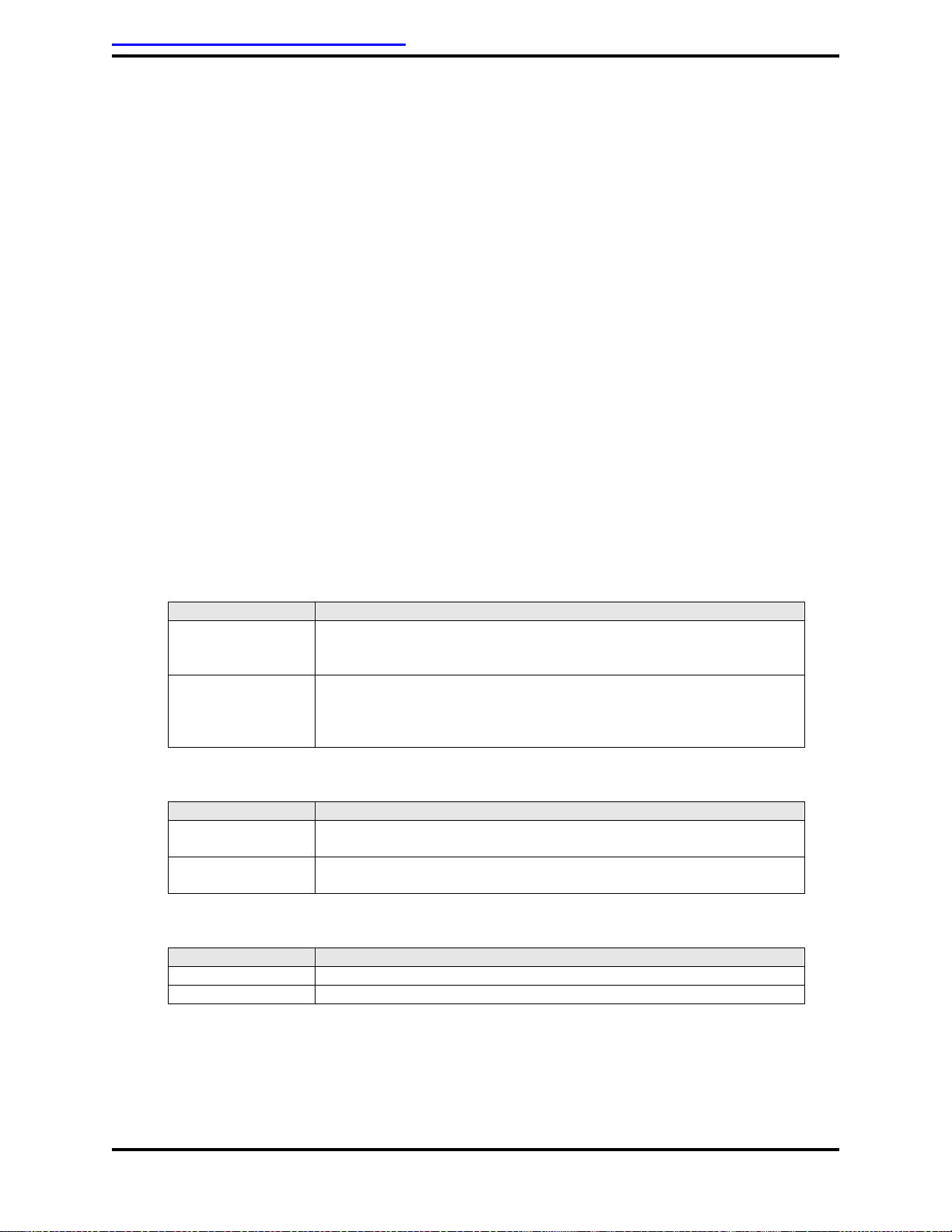
3.7 Electrical Characteristics
3.7.1 Electrical Specifications
Electrical Nominal Power 1 A at +28 VDC
Maximum Power 1.5 A at +28 VDC
Operating Voltage Range +18 to +32 VDC
+28 VDC preferred
Audio Output Output Type Balanced, Stereo
Output Level 2 VRMS (optimum)
1 VRMS (minimum)
Output Impedance 600
Frequency Response 20 Hz to 20 kHz
Signal-to-Noise Ratio 85 dB or greater
Total Harmonic Distortion
(THD) 0.1% or less
General Video
Video Interfaces VGA, Composite Video,
and SDI
VGA Video Output SVGA video output up to 800 x 600
resolution @ 32-bit color
Composite Output Level 1.0 V(p-p)
Video
Output Impedance 75
Video Formats NTSC
SDI Video
Output Output Type SMPTE-259
Data Rate 270 Mbps
3.7.2 Input Power
This unit operates at a MAXIMUM power consumption of 1.50A at
+28VDC with an operating voltage range of +18VDC (minimum) to
+32VDC (maximum). QUIESCENT operating power consumption,
by design, should not exceed 1.00A at +28VDC. Final power
consumption is at the discretion of the designer, but must not
exceed the stated MAXIMUM.
3.7.3 Grounding / Bonding
This unit provides for common circuit ground and chassis ground
connections. Both circuit and chassis grounds are referenced to
pin two (2) of connector J1. Circuit/chassis ground connection shall
be bonded to an electrically conductive chassis mounting point or
DeCrane Aerospace Audio International MAP-9101-10x-x Installation Manual
Document # 540372, Rev IR, 12/2008 Page 17 of 29
frame ground with less than 0.010-ohm resistance using less than
50-ohm impedance cable.
3.7.4 Power Interruption
This unit is capable of maintaining full normal operation during
power interruptions not greater than 200msec. Due to the
operational application of this device, connection to an external
uninterruptible power supply (UPS) may be desirable depending
upon customer-specific application requirements.
Any specific attempts to comply with the required power interruption
time duration shall also consider minimization of in-rush current at
power-up.
3.8 Mating Connector Information
3.8.1 MAP-9101-100-x Mating Connectors
All wiring harnesses to the unit are supplied and fabricated by the
installing agency.
J1 CONNECTOR
PART NUMBER
MATING CONNECTOR
MAP-9101-100-1 CBC25W3F14000 Female Plug or equivalent
Size 8 Contact: FCC4102D (x3)
(Positronic Industries)
MAP-9101-100-2 5025W3SCK99AIOX Female Plug with male jackscrews or
equivalent
Size 8 Contact: D130344 (x3)
(ITT Cannon)
J2 CONNECTOR
(RS-232 SERIAL PORT)
PART NUMBER
MATING CONNECTOR
MAP-9101-100-1 RD9F10JVL0 Female Plug or equivalent
(Positronic Industries)
MAP-9101-100-2 DEMA-9S with Female Plug with male jackscrews or equivalent
(ITT Cannon)
J5 & J6 CONNECTOR
(USB PORT #1 & 2)
PART NUMBER
MATING CONNECTOR
MAP-9101-100-1 USB Type A Plug
MAP-9101-100-2 USB Type A Plug

DeCrane Aerospace Audio International MAP-9101-10x-x Installation Manual
Document # 540372, Rev IR, 12/2008 Page 18 of 29
J7 CONNECTOR
(10/100BASE-T ETHERNET PORT)
PART NUMBER
MATING CONNECTOR
MAP-9101-100-1 95043-2891 (RJ45 Plug) or equivalent
(Molex)
MAP-9101-100-2 95043-2891 (RJ45 Plug) or equivalent
(Molex)
J8 CONNECTOR
(SVGA)
PART NUMBER
MATING CONNECTOR
MAP-9101-100-1
DD15M10JVL0 Male Plug or equivalent
(Positronic Industries)
MAP-9101-100-2 DEMA15PK87Male Plug with male jackscrews or equivalent
(ITT Cannon)
3.8.2 MAP-9101-101-x Mating Connectors
All wiring harnesses to the unit are supplied and fabricated by the
installing agency.
J1 CONNECTOR
PART NUMBER
MATING CONNECTOR
MAP-9101-101-1 CBC25W3F14000 Female Plug or equivalent
Size 8 Contact: FCC4102D (x3)
(Positronic Industries)
MAP-9101-101-2
5025W3SCK99AIOX Female Plug with male jackscrews or
equivalent
Size 8 Contact: D130344 (x3)
(ITT Cannon)
J2 CONNECTOR
(RS-232 SERIAL PORT)
PART NUMBER
MATING CONNECTOR
MAP-9101-101-1 RD9F10JVL0 Female Plug or equivalent
(Positronic Industries)
MAP-9101-101-2 DEMA-9S with Female Plug with male Jackscrews or equivalent
(ITT Cannon)
J5 CONNECTOR
(USB PORT #1)
PART NUMBER
MATING CONNECTOR
MAP-9101-101-1 USB Type A Plug
MAP-9101-101-2 USB Type A Plug
J6 CONNECTOR
(USB PORT #2)
PART NUMBER
MATING CONNECTOR
MAP-9101-101-1 USB Type A Plug
MAP-9101-101-2 USB Type A Plug
DeCrane Aerospace Audio International MAP-9101-10x-x Installation Manual
Document # 540372, Rev IR, 12/2008 Page 19 of 29
J7 CONNECTOR
(10/100BASE-T ETHERNET PORT)
PART NUMBER
MATING CONNECTOR
MAP-9101-101-1 95043-2891 (RJ45 Plug) or equivalent (Molex)
MAP-9101-101-2 95043-2891 (RJ45 Plug) or equivalent (Molex)
J8 CONNECTOR
(SVGA)
PART NUMBER
CONNECTOR
MATING CONNECTOR
MAP-9101-101-1 DD15F10JV30
(Positronic Industries) DD15M10JVL0
(Positronic Industries)
MAP-9101-101-2 DEMA15SK87 DEMA15PK87
J9 CONNECTOR
PART NUMBER
MATING CONNECTOR
MAP-9101-101-1 RD15M10JVL0 or equivalent
(Positronic Industries)
MAP-9101-101-2 DEMA-15P with male jackscrews or equivalent
(ITT Cannon)
This manual suits for next models
6
Table of contents
Popular Server manuals by other brands


IBM
IBM RS/60000 Series Site and Hardware Planning Information

GRASS VALLEY
GRASS VALLEY FT instruction manual

Polycom
Polycom Real-Time Media Conferencing Platform RMX... Migration guide

HP
HP D6030A - NetServer - E50 datasheet

Digital Watchdog
Digital Watchdog Blackjack BOLT DW-BJBOLT2T-LX quick start guide

Advantech
Advantech RS-200-RT user manual

KYLAND Technology
KYLAND Technology PTS-10 Operation manual

Asus
Asus TS100-E6 PI4 user guide

Dell
Dell PowerEdge 1550 installation guide

IBM
IBM Power System LC922 Quick install guide

HP
HP ProLiant ML350e Gen 8 v2 Product End-of-Life Disassembly Instructions

xFusion Digital Technologies
xFusion Digital Technologies FusionServer 5288 V7 manual