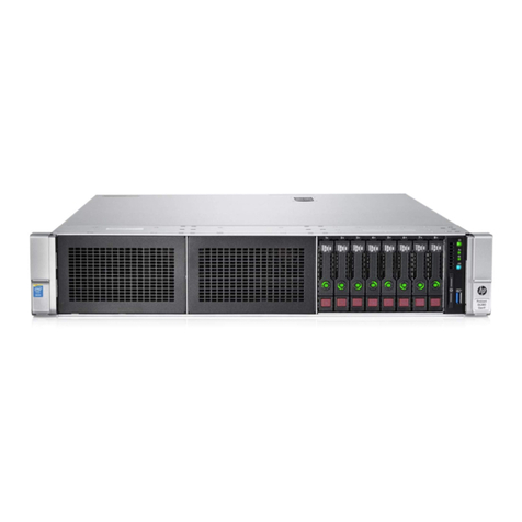
DECRYPTUM PR 2080TI/12 4U User manual

DECRYPTUM PR 2080TI/12 4U. USER MANUAL 1
CMNO LTD. 2019
DECRYPTUM
PR 2080TI/12 4U
USER MANUAL

DECRYPTUM PR 2080TI/12 4U. USER MANUAL 2
Congratulations on purchasing your DECRYPTUM Professional Computing
Device. We are pleased to welcome you as a customer. These user instructions
contain all safety information and instructions necessary for using your
DECRYPTUM PR 2080TI/12 4U.
Before using your device, please familiarise yourself with all relevant
information. Only use the device in the manner described and for
the applications indicated. If you pass on the device, be absolutely
sure to also pass on all instructions and other relevant documents.
!

DECRYPTUM PR 2080TI/12 4U. USER MANUAL 3
OVERVIEW
UNPACKING AND CHECKING THE CONTENTS
SETTING UP
STARTING UP THE DEVICE
THE LIST OF ACTIONS IN CASE OF GPU FAILURE
POWER SUPPLY UNIT
LED INDICATORS
4
6
9
10
12
14
1.
2.
3.
4.
!
!

DECRYPTUM PR 2080TI/12 4U. USER MANUAL 4
UNPACKING AND CHECKING
THE CONTENTS
Unpack the devices — computing unit and cooling unit (free cooler).
Check if the package contains all of the components ordered (Pic.1):
• DECRYPTUM PR 2080TI/12 4U main unit x1 A
• Free cooler x1 B
• Tubings with Quick Disconnect Couplings x2 C
• Switching Cable x1 D
• Power Supply x3 E
Make sure that both devices are not visibly damaged. If there is visible
damage, do not use the devices and contact the manufacturer.
1.1
1.2
1.3
1.
A B
C D
Fans
Reboot
button
Start
button
E
Pic.1

DECRYPTUM PR 2080TI/12 4U. USER MANUAL 5
SETTING UP
Place both devices in a 4U rack or on an even horizontal surface.
When installing in a 4U rack, it is advisable to place the free cooler
under the main unit.
Connect the devices with hoses in accordance with the color coding
on the Quick Disconnect Couplings (QDC) (see Pic.2). Respectively
connect blue to blue and red to red QDC on the devices and hoses.
QDC should be installed tightly, until a typical click.
2.1
2.2
2.
Pic.2
Red
to red
Blue
to blue

DECRYPTUM PR 2080TI/12 4U. USER MANUAL 6
SETTING UP
Connect the free cooler to the main unit using the supplied switching
cable (see Pic.3)
2.3
2.
IT IS FORBIDDEN TO TURN ON THE MAIN UNIT
WITHOUT CONNECTING THE FREE COOLER TO IT!
!
WARNING
Pic.3

DECRYPTUM PR 2080TI/12 4U. USER MANUAL 7
Connect a 220v power cable to both units of the complex (free cooler
and main unit) (see Pic.4)
THE FREE COOLER MUST BE CONNECTED TO A 220V
NETWORK BEFORE TURNING ON THE COMPUTING UNIT.
AN UNCONNECTED FREE COLLER UNIT CAN CAUSE
DAMAGE TO THE COMPLEX!
SETTING UP
2.4
2.
!
WARNING
Pic.4

DECRYPTUM PR 2080TI/12 4U. USER MANUAL 8
Set the 3-position button (see Pic.5) on the free cooler to position I
if the air temperature in the operating room is <18°C, to position II
if the temperature is >18°C.
Make sure that the free cooler power button is in position I
Connect the monitor and keyboard to the computing unit.
SETTING UP
2.5
2.6
2.7
2.
Pic.5

DECRYPTUM PR 2080TI/12 4U. USER MANUAL 9
STARTING UP THE DEVICE
Push the start button on the front panel of the main unit to switch
the device on. The free cooler should turn on automatically. Fans should
start rotating. If for some reason the free cooler does not start, imme-
diately turn off the main unit.
A diagnostic screen saver for card denition in the BIOS should appear
on the connected monitor (see Pic.6).
Make sure all 12 cards are displayed in green, if any card is marked in red
(see Pic.7) nd the faulty card according to the connection slot numbers
in the BIOS screen.
3.1
3.2
3.3
3.
Pic.6 Pic.7
TO REPAIR A FAULTY GPU, DISCONNECT THE MAIN UNIT
FROM THE 220V POWER SUPPLY.
!
WARNING
Error
(Red color)

DECRYPTUM PR 2080TI/12 4U. USER MANUAL 10
STARTING UP THE DEVICE3.
Try to re-plug the motherboard — GPU connecting cable (see
Pic. 6-7). The number on the cable and on the card corresponds
to the number displayed in the BIOS diagnostic message.
Re-plug the GPU riser. Do it after carefully removing the protec-
tive adhesive tape from the Pci-e connector.
Check the condition of the riser/GPU power cables.
Disconnect the main unit and reconnect power.
If none of the abovementioned steps help, contact your Comino
representative for troubleshooting.
After each of the above mentioned steps, connect the com-
puting unit to the 220v network and try to switch it on.
3.4.1
3.4.2
3.4.3
3.4.4
3.4.5
IT IS STRONGLY FORBIDDEN TO START REPAIRING
A DEVICE WHICH IS CONNECTED TO A 220V NETWORK.
DANGER
THE LIST OF ACTIONS IN CASE OF GPU FAILURE
!
Pic.8 Pic.9

DECRYPTUM PR 2080TI/12 4U. USER MANUAL 11
In case all the cards were initially determined correctly, wait for the pre-in-
stalled operational environment to load.
If in the manager any GPU is marked with a yellow triangle, delete it from
the devices list by pressing the right button on an erroneously working GPU
— (RMB on the faulty GPU — remove the device) and reboot the operating
system.
If after rebooting and re-installing the drivers automatically the card in the
device manager continues to display with an exclamation mark, you should
contact your Comino representative to x the problem.
STARTING UP THE DEVICE
After loading the OS, go to the
device manager (right button click
on the “My computer” icon or right
button click on the “Start” icon
in the lower left part of the Windows
desktop) and make sure that all
12 cards are displayed correctly
without errors (see Pic.8).
3.5
3.6
3.7
3.8
3.
Pic.10

DECRYPTUM PR 2080TI/12 4U. USER MANUAL 12
Your system includes Comino Energia power supply unit (PSU) containing 3
power modules (PM), 1600W each.
Each PM supports 2 types of AC source connection:
• line to neutral 220V AC (EU standard) (see Pic.11)
• line to line 208V AC (US standard) (see Pic.12)
EU standard
US standard
POWER SUPPLY UNIT
4.1
4.
Neutral
220V
220V
220V
Grounding
N
AA-N 220VAC
B-N 220VAC
C-N 220VAC
CORRECT
LINE TO NEUTRAL
B
C
G
WRONG!
LINE TO NEUTRAL
Neutral
120V
120V
120V
Grounding
N
AA-N 120V 1-Ph
B-N 120V 1-Ph
C-N 120V 1-Ph
B
C
G
LINE TO LINE
WRONG!
A-C 380VAC
A-B 380VAC
B-C 380VAC
Neutral
220V
220V
220V
Grounding
N
A
B
C
G
LINE TO LINE
CORRECT
A-C 208V 1-Ph
A-B 208V 1-Ph
B-C 208V 1-Ph
Neutral
120V
120V
120V
Grounding
N
A
B
C
G
Pic.11
Pic.12
Electricity works must be coordinated with a certied electrician.
Unauthorized works can cost you your life.
The created line-to-line connection must only be used to connect
Decryptum PR 2080Ti/12 4U and must not be used in everyday life.
IMPORTANT
!

DECRYPTUM PR 2080TI/12 4U. USER MANUAL 13
Starting Current
Maximum starting current for each PM is 35A. Please consider this when
designing your power supply network.
Branch circuit breakers
If one branch is supplying 2 or 3 PMs, please use C25 circuit breaker.
For supplying each PM separately, please install C16 circuit breaker in each
branch.
<10A@200-240VAC/160-340VDC @full load
4.2
4.3
4.4
EACH POWER MODULE SHALL OPERATE WITHIN LIMITED
INPUT VOLTAGE RANGE AS DEFINED IN TABLE 1.
!
ATTENTION
AC input voltage
Frequency
DC input voltage
Input current
UNITS
VAC
Hz
VDC
MAX
264
63
400
RATED
200-240
50-60
240-336
MIN
200
47
192
Table 1
POWER SUPPLY UNIT4.

DECRYPTUM PR 2080TI/12 4U. USER MANUAL 14
Line Fuse
Each PM is supplied with a fast blow type fuse in the live line input wire. It
protects PM from short circuit inside PM.
Line fuse is resistant to starting current or inner protection circuits. In case
line fuse is blown up, please check internal components of the PM for dam-
ages or contact the developer.
Eciency
Power Supply Unit is certied with 80 Plus Platinum level certicate of e-
cient energy use. Maximum eciency reaches 94% at 50% load.
Grounding
The output connector ground pins should be connected to the safety
ground (power supply enclosure). This grounding should be well designed
to ensure passing the max allowed common mode noise levels. The power
supply should be provided with a reliable protective earth ground. All sec-
ondary return circuits should be connected to protective earth ground.
4.5
4.6
4.7
POWER SUPPLY UNIT4.

DECRYPTUM PR 2080TI/12 4U. USER MANUAL 15
LED Indicators
PM front panel is supplied with a LED-lamp to indicate its status. Check
Table 2 for details.
* — Under Voltage Protection, Over Voltage Protection, Over Current Protection, Over Temperature Protection.
4.8
LED COLOR
Green
Green, ashing (approxi-
mately every second)
Green, slow ashing
(approximately every
3 seconds)
No color
Orange, ashing (approxi-
mately every second)
Orange
Orange
POWER SUPPLY STATUS
Normal operation, status OK.
Standby mode.
Low power mode (saves energy).
No input power
Attention required!
Warning events: high temperature warn-
ing, fan fail warning, over current warning.
Attention required!
AC cord unplugged or DC power lost.
Attention required!
Power supply critical event causing a
shutdown: UVP, OVP, OCP, OTP*.
POWER SUPPLY UNIT4.
Table 2

DECRYPTUM PR 2080TI/12 4U. USER MANUAL 16
Manufactured by CMNO LTD. for Passware, Inc.
800 West El Camino Real, Suite 180
Mountain View, CA 94040
Other manuals for PR 2080TI/12 4U
1
Table of contents
Popular Server manuals by other brands
Sun Microsystems
Sun Microsystems Netra T5220 Service manual
Sun Microsystems
Sun Microsystems Netra X1 user guide
Hitachi
Hitachi Advanced Server DS220 Hardware guide
Korenix
Korenix AnyBus-X Installation leaflet

LG-Ericsson
LG-Ericsson iPECS-CM Operation manual
HP
HP T5735 - Compaq Thin Client Administrator's guide
Cisco
Cisco UCS C240 M4 Installation and service guide
Sun Oracle
Sun Oracle T5120 installation guide
Lenovo
Lenovo ThinkServer RD240 Instructions pour l’installation en armoire

QNAP
QNAP VioStor CMS user manual

Neoware
Neoware Neoware e140 - Thin Client user manual
Supero
Supero SuperServer 6024H-32 user manual
