Deekax TALTERI DIVK-C 99 CD User manual
TALTERI
DEEKAX Air Oy
Patruunapolku 4 Tel. 0207 912550
79100 LEPPÄVIRTA www.deekaxair.fi
R
AIR EXCHANGE EQUIPMENT
INSTALLATION AND USER
MANUAL
THE QUALITY GOALS OF AIR CONDITIONING COME TRUE
WITH THE RECOVERY SYSTEM
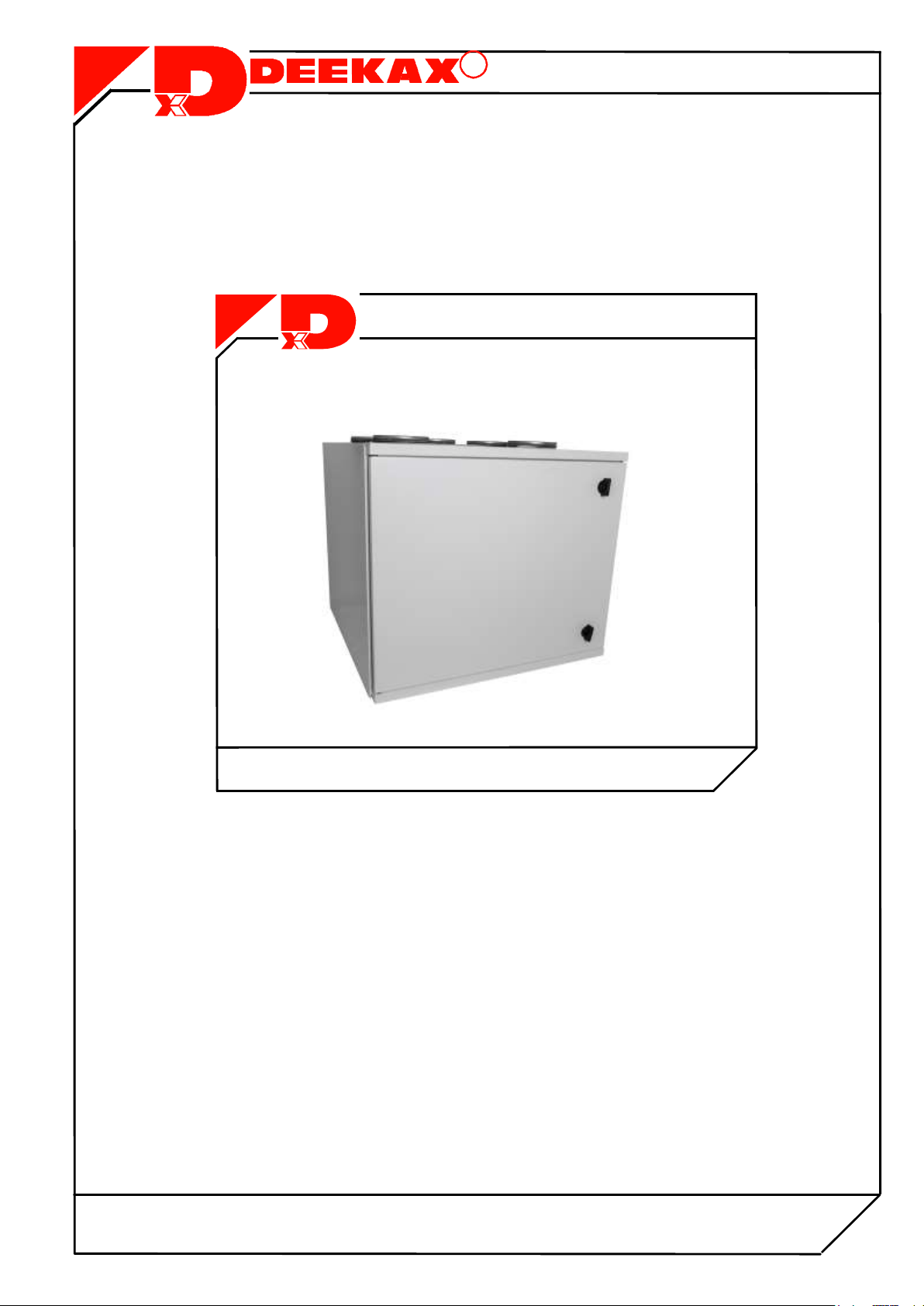
TALTERI removes used air from interior and brings in fresh air.
Humidity and impurities are exhausted through thermal recovery
unit that heats the filtered ambient air cost-effectively. The fresh
warm air is channelled draught-free and noise-free into the
premises in necessary quantities.
ENSURE THE QUALITY OF AIR EXCHANGE!
DIVK-C 99 CD
QUALITY TESTED

21
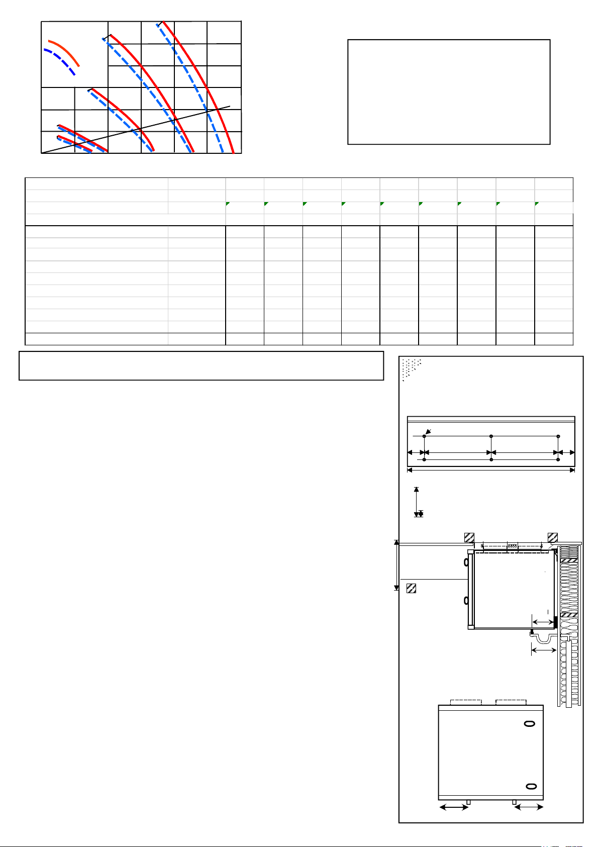
EQUIPMENT DETAILS AND TECHNICAL DATA
1 Exhaust air out.............. . 125 or 160 mm
2 Outdoor air for the system ..... 125 or 160 mm
3 Extract air for the system...... 125 or 160 mm
4 Supply air indoors................. 125 or 160 mm
5 Kitchen exhaust .................... 125 mm
6 Door switch
7 Supply fan, adjustable...........EC 166 W
8 Extract fan, adjustable..........EC 166 W
9 Heat exchanger
10 Postheater, adjustable........ 500 W
11 Preheater, adjustable .........1000 W
12 Extract air filter (G4) ISO Coarse>75%
13 Supply air filter (F7) ISO ePM1
14 Supply air filter (G4) Coarse>75%
16 Preaheater manual overheat protection
17 Postheater manual overheat protection
18 Summer bypass appliance
19 Exhaust of condensing water
20 Humidity transmitter(optional)
21
T
ouch screen
control panel
for setting up
or contro
l
ing
the
HRV
unit
(optional)
14
13
16
8
19
9
6
7
10 17
12
20
18
11
2
50
100
150
200
250
300
350
20 40 60 80 100 120 140
30%
100%
Airflow
l/s
Pa
80%
60%
40%
400
450
Extract air
Supply air
C99-160
EXTERNAL PRESSURE OF THE DUCTWORK
Fan speed 20 30 40 50 60 70 80 90 100
Fan input power W 12 18 26 41 69 105 158 223 283
Sound pressure level (LpA) l/s 16/15 25/22 38/33 52/44 68/60 83/72 98/86 112/101 122/112
to the room (sound adsorbtion 10m2) dB(A) 15 19 21 26 30 35 37 40 42
Sound power level in
Hz
E S
E S
E S
E S
E S
E S
E S
E S
E S
the extract(E)and the supply(S)
63
29 41
36 53
42 56
47 62
51 66
53 70
56 72
58 74
58 75
duct by octave bands, Lw(dB)
125
23 38
32 48
39 53
44 59
50 63
54 66
56 69
59 71
58 72
250 25 33 33 41 40 47 45 53 50 57 54 61 57 64 59 67 60 68
500 16 35 25 44 31 50 36 55 41 59 45 62 47 66 50 69 50 70
1000 15 29 27 42 33 48 37 53 40 57 43 60 45 62 47 64 48 65
2000 * 22 14 37 22 46 28 53 33 58 36 62 39 65 41 68 41 69
4000 * 8 4 28 14 39 21 46 26 52 31 57 34 60 37 63 37 65
8000 * * * 16 4 30 12 40 19 47 23 52 27 56 30 59 30 61
Total sound power level L
wa
19 33
29 45
35 52
40 58
44 63
48 66
51 69
53 72
53 74
Input
power
C99-160
1 EXHAUST AIR
2 OUTDOOR AIR
3 EXTRACT AIR
4 SUPPLY AIR
5 KITCHEN EXHAUST
DUCT OUTLETS
HANDEDNESS RIGHT(R)
4 EXHAUST AIR
3 OUTDOOR AIR
2 EXTRACT AIR
1 SUPPLY AIR
5 KITCHEN EXHAUST
DUCT OUTLETS
HANDEDNESS LEFT(L)
DOOR
In the picture is shown a right handed (R) unit
3
TALTERI DIVK-C 99 INSTALLATION
WALL ATTACHMENT
The wall mounting kit includes a ceiling mounting plate, a wall-mounting plate
and 15 mm thick insulation pieces. A wall-mounting plate is installed about 25 mm
below the roof surface.The wall attachment plate will be fixed to the wall and then
the unit is lifted up to the attachment plate, checked into perfectly horizontal position
and then drill holes for the metal screw through the mounting plate in to the bottom of
the machine.Roof moldings can be put around the machine.
KITCHEN EXHAUST DUCT
The channel output (5) in intended for exhaust channel of the cooker hood.
If the exhaust channel of the cooker hood is not in use, it must close.
If the cooker hood is connected to the kitchen exhaust duct ( heat recovery bypassed)
all the basic ventilation holes of the cooker hood's damper must be closed
and in the kitchen it is needed a separate extract air valve which is connected to
the extract air duct.
The air exchange unit is meant for warm inner facilities. Suitable installation spots are,
among others, office, dressing or household facilities and technical or warm storages. In case
the temperature of the installation location is lower than room temperature, the factory settings
of the appliance must be changed to obtain faultless functioning. The unit can not be installed
into cold outer premises or garages.
UPPER BASE DUCT
The channelling is usually mounted to the upper base thermal insulation.
The steam barrier puncture must be carefully sealed. While installing the unit to
channels, steel steam barrier plate, supplied as extra, will come handy. The steam
barrier plate is attached securely between the roof trusses, 10 mm smaller hole
must be cut into the gasket mat and channels are installed through the plate.
The steam barrier must be hermetically taped.
The unit can be attached right to the steam barrier plate with four M8 thread bars
at desired height. Note the measurements of the steam barrier plate during the
installation process.
The bolts and thread bars are purchased separately.
CONDENSATE
Condensate drain is connected to the machine condensate connector (3/8 "external thread).
Condensate can be made at a least 10 mm in the bore copper pipe or Relatively stiff hose.
The water pipe Making about 10 cm in the water trap and the tube is connected to a floor drain.
The water line shouldnt be connected directly to the sewer.
TALTERI
KONEEN OVI
177
177
Kondenssivesiliitäntä
oikea (R)
Kondenssivesiliitäntä
vasen (L)
157
43
200 200 43
20
90
130
485
Seinäkiinnityslevy
6kpl D=6,5mm
172
EXTERNAL PRESSURE OF THE DUCTWORK
Airflow
extract air
supply air
Fan speed % 20 30 40 50 60 70 80 90 100
Fan input power W 12 16 23 35 51 113 156 221 290
Sound pressure level (LpA) l/s 17/16 22/20 33/30 46/42 59/55 72/68 82/78 95/90 106/98
to the room (sound adsorbtion 10m2) dB(A) 15 18 22 27 30 35 38 39 42
Sound power level in
Hz
E S
E S
E S
E S
E S
E S
E S
E S
E S
the extract(E)and the supply(S)
63
* 37
23 49
33 54
38 58
42 61
44 65
47 68
50 71
52 72
duct by octave bands, Lw(dB)
125
23 36
31 46
41 53
46 57
50 60
53 64
56 66
58 69
59 70
250 22 30 29 39 35 44 40 49 46 54 49 57 52 61 54 64 56 66
500 11 29 19 40 25 45 29 50 34 54 37 57 40 61 43 63 45 65
1000 11 24 21 38 27 45 32 50 35 54 38 57 41 59 42 62 44 63
2000 * 18 9 34 18 44 24 51 28 56 32 59 34 62 37 64 38 66
4000 * 4 * 25 11 37 18 45 24 50 28 54 31 58 34 61 36 64
8000 * * * 11 * 27 6 36 13 44 18 48 21 52 24 56 26 58
Total sound power level Lwa 15 28 23 41 30 49 35 55 39 60 43 63 45 66 48 69 49 71
C99-125
Input
power
Control
voltage
Airflow
% 40 60 80 100
23 33 42 50
KITCHEN EXHAUST AIRFLOW
l/s
Total sound
power level of
the kitchen
exhaust duct
45 55 61 64
Lwa
C99-125
50
100
150
200
250
300
20 40 60 80 100 120
30%
100%
l/s
Pa 80%
60%
40%
4
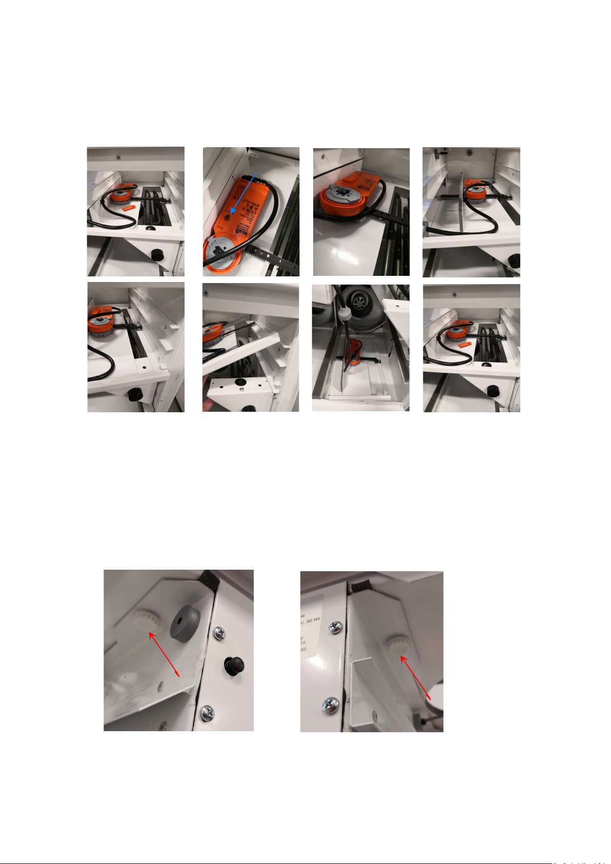
REMOVAL OF THE SUMMER BYPASS PLATE
In order to facilitate the installation of the ceiling mounting plate bolts, the summer bypass plate
can be removed during installation. The heat exchanger and the filters are removed from the machine.
If the the plate is in the winter position (Figure. 1), the motor is released with the magnet.
The magnet is placed to the position shown in the figures 2 and 3. The summer bypass plate is pulled
open by hand (Figure 4). Pull the plate outwards (Figure 5) and lift the outer edge above the filter brackets (Figure 6).
The summer bypass plate can be placed on the bottom of the machine (Figure 7). Reassemble in the reverse order,
remove the magnet from the motor, install the grommet and the motor cable as shown in the figure 8.
1. 2. 3. 4.
5. 6. 7. 8.
REMOVAL OF THE ELECTRICAL CONNECTION BOX
The electrical connection box can be removed, for example for maintenance or modbus termination, by
removing the summer bypass plate and then loosening the thumbscrews, as shown in the figures below.

DIVK
-
C
99
INSTALLATION TO A SUSPENDED CEILING
The ceiling-mounting plate is attached
to the roof with M8, thread bars (not included in the
delivery).
RUBBER SILENCER
WASHER
NUT
5
5mm
40-50
mm
The head of the threaded bar can not
reach below the bottom of the plate.
The unit will be pushed to the mounting plate and
tightened with four M8 bolts against the mounting plate
so that the cover seal of the unit is evenly sealed against
the m
ounti
ng plate
, not tighter.
MOUNTING PLATE BINDING
UPPER SURFACE IS
INSTALLED 5 mm
BELOW THE ROOF SURFACE
LEAVE A 40-50MM GAP
BETWEEN THE CEILING AND
THE FRONT EDGE OF THE
MOUNTING PLATE
SERVICE HATCH
M8 THREADED BAR
BACKUP NUT
THE UNIT IS PULLED
INTO THE MOUNTING
PLATE “RAILS”
WASHER
BOLT M8X40
THE UNIT IS ATTACHED
TO THE MOUNTING
PLATE FROM THE INSIDE
BY FOUR M8 BOLTS
MEASURES OF THE MOUNTING PLATE
SERVICE HATCH SERVICE HATCH
DOOR

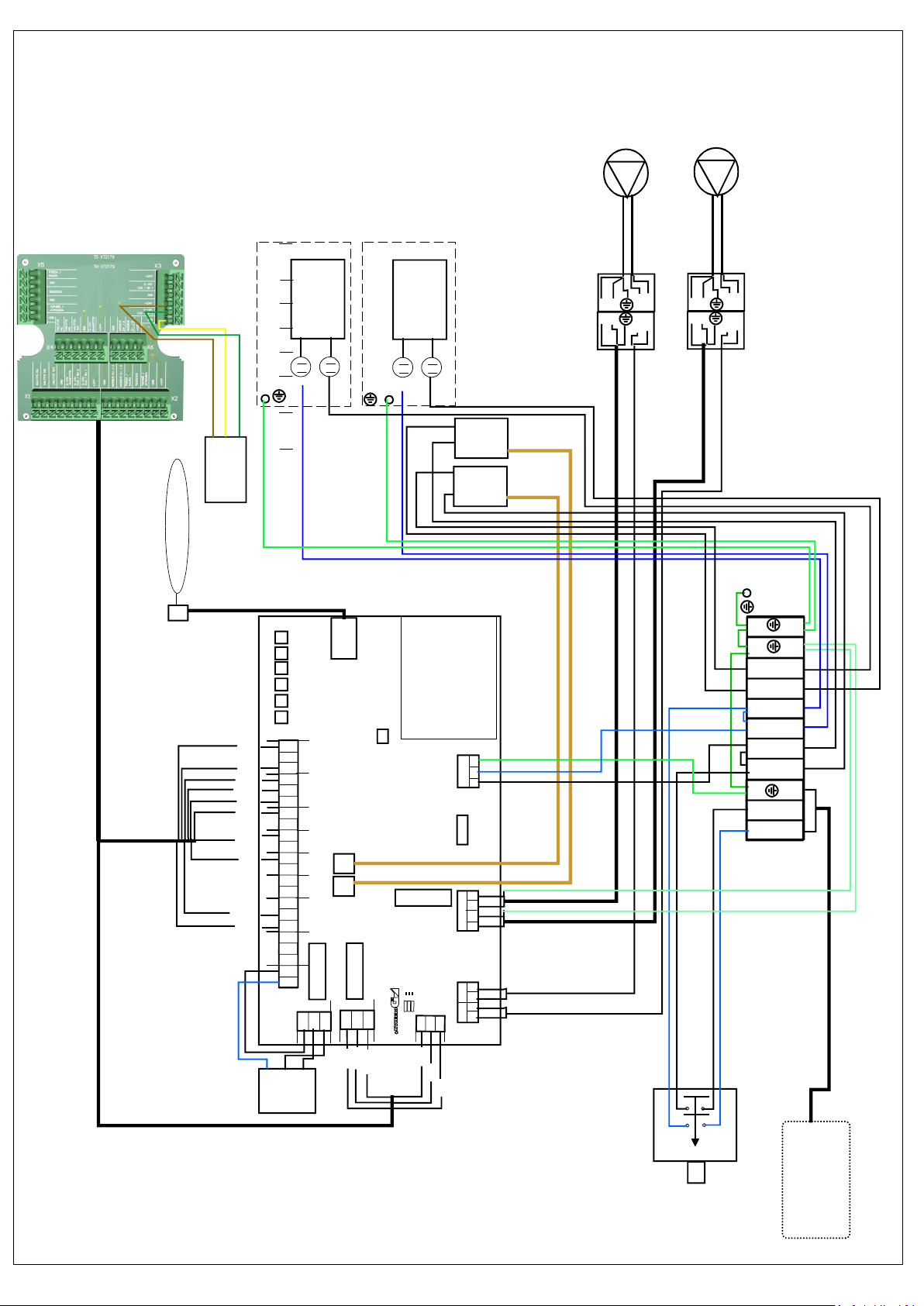
ELECTRICAL CONNECTIONS
Electrical connections must be done following the installation manual
and wiring diagram.
ELECTRICAL CONNECTIONS CAN BE DONE ONLY BY
AN ENTREPRENEUR WITH RESPECTIVE INSTALLATION RIGHTS.
6
VAK
Alarm and operation
indication
max 24 V
as contact tip information
from the unit
0-10V
GND
24V
CO2
trans-
mitter
VAK
0
0-10V
KITCHEN HOOD
0-10v control
0
0-10V
PC EC
PG EC
DS EC
DSA EC
Input
-power cord
230V,
50 Hz
10 A
NO
NC
0-10V
GND
24V
RH
trans-
mitter
-
+
MODBUS
GND
D+/ A
D- / B
Out-of-home
switch
Pulse
switch
switch
Under pressure
compensation
set value 0 as
contact tip infor-
mation
Fireplace
Over pressure
KITCHEN HOOD
boosting with
contact tip information
NO
COM
NC
open
closed
Pulse
switch
Boost
switch
switch
set value 0
as contact tip
information
Boost
switch
Extended time
Cooling
radiator
actuator
DC 24 V
0-10v
set value 0
as contact tip
information
Internal connection of the HRV unit
Input,
-power cord
230V,
50 Hz
10 A
RJ12 2,5 m AHU
To control panel
Input
230V,
50 Hz
10 A
-power
cord
(plug)
(
Pulse
switch
Input
-power
cord 1 m
(plug)
connection box
cable 1 m
External connections of the HRV unit are connected to the connection
box located on the top the unit.
The unit is equipped with a power plug.
The unit is set up and the setvalue changes are made via a separate AHU
control panel. The control panel is connected to the cable above the unit
with the RJ12 connector.
The following can be connected as
accessories:
- Carbon dioxide transmitter;
- Humidity transmitter;
- Separate Over pressure or Extended
time switch (pulse switch);
- Separate Boost switch (pulse switch);
or setting off as pre-data (for instance,
sauna oven, stove hood);
- Remote control or out-of-home switches
(pre-data);
- Differential pressure switches for filters;
- External speed control 0-10V.
- Modbus.
The functions can be operated through
maintenance and setup menus of the
operating panel.
7
Br-gr
Ye-br
Wh-ye
Red
Blue
Pink
KS KS
T1 T2 T3 T4 T5 T6
OUT SUP-
PLY
EX-
TRACT
EX-
HAUST
WATER
PRE
HEATER
POST
HEATER
CONTROLL PANEL
230VAC
L N PE
FUSE
TEMPERATURE SENSORS
+24 0 0-10
CO2/%RH1
+24 00-10
CO2/%RH2
OVER-
PRESSURE/
EXTENDED
TIME
BOOS-
TING
0-10
OUT-OF-
HOUSE/
REMOTE
+24 0 0-10
COOLING
+24 0
WATER
RADIATOR
FILTER
+24 0
HEAT RECOVERY
BYPASS
WIN-
TER
YHT
SUM-
MER
ALARM
NC
YHT
NO
Circuit board
ECU
R
EXTRACT SUPPLY
0-10 0-10
0 0
SUPPLY /EXTRACT
N NU U
TRIAC
PREH.
TRIAC
POSTH.
SUPPLY
FAN
EXTRACT
FAN
N3 2 1
K
S
N3 2 1
KS
N3 2 1
K
S
N3 2 1
K
S
1
-
2
+
3
+
Belimo CH 24
Summer
bypass
POST
HEATER
50c 90c
PRE
HEATER
50c 90c
1000W
500W
MODBUS
A/D+
B/D-
0
O O O
O O O
O O O
ON OFF BIAS B
ON OFF Term
ON OFF BIAS A
RJ12 3 m AHU CONTROL PANEL
DOORSWITCH
N
4
L
1
L
2
N
3
L
N
E
J
Input
230V,
50 Hz
10 A
-power
cord
(plug)
( IU )
Black
Violet
Gr-Pi
R-bl
Wh-gr
Grey
Yellow
Green
Brown
White
C99 CD
Humidity trans-
mitter
Optional
0-10
0
+24

8
INTRODUCTION OF THE AIR EXCHANGE SYSTEM
BEFORE OPERATING YOUR AIR EXCHANGE SYSTEM,
MAKE SURE THAT:
- There are no loose objects within the unit or the air impeller;
- The coverings of construction-time are removed from
the outlet- and exhaust air holes;
- All isolations and steam barriers are in order;
- The heat transfer and fans are in their places;
- The condensing water outlet is installed and the water
is drained out;
- The air impellers and their adjusters are in working order;
- Afterheating is regulated and working.
USAGE DURING INSTALLING
The air exchange unit should be started as soon as
installation permits.
Efficient air exchange promotes drying of the constructions
and prevents damage.
In case channelling has not been completed, fans and adjustments
are missing,filter paper must be used in place of fans to keep
the channels clean andprovide sufficient counterpressure for
preventing overload. The unit must be used with full power and
check the drainage of the condensing water.
The appliance, filters and heat exchangers must be cleaned
and the systemadjusted after the construction works are
completed.
BASIC ADJUSTMENT OF AIRFLOW
The unit alone can not produce good interior ear in case
the channels and fans are installed carelessly and main
adjustments are not made.
Regulate the inlet and outlet fans to the planned positions
and start the unit
at design power speed. Measure the airflow in outside- and
exhaust air channels.
The outlet must be 5-10% higher than inlet. Check the
pressure level of thechannels by checking from the fans and
adjust it accordingly to obtain the pressure level
for vents; adjust and lock the pattern.Draw measuring- and
adjustment records!
USAGE AND CORRECT LEVEL OF AIR EXCHANGE
The air exchange level is regulated by changing the
working speed of the air impeller from the operating panel.
Airflow of different adjustable positions can be seen
from table 2.
Adjustable position 1 is for basic air exchange for an empty house.
Adjustable position 2 and 3 are normal working positions.
Adjustable position 4 and 5 are efficiency positions (i.e. for saunas).
The correct usage positions will be found by experience;
observing the purity of the air or sultriness when coming in
from outside, observing moisture on the windows or drying
of the sauna.
AFTERHEATING AND SUMMER BYPASS OF INLET AIR
The unit is equipped with 500 W electrical battery operated
by the means of triac-adjuster operated by the operating device
for afterheating the heat recovered inlet air.
The temperature of inlet air is usually regulated to +17C.
The temperature may be adjusted to higher during winter so there
would be no draught like feeling. In case of severe frost and
efficiency mode the heating power might turn out insufficient –
in such circumstances, the air exchange should be reduced.
The overheating protection launched during malfunctioning
must be annulled manually.
During summertime, the HR-exchanger element on the bypass plate
will be closed so the exhaust air will not warm up the inlet air.
CONDENSING WATER AND FREEZING PREVENTION
As the extract air cools in the heat exchanger, the moisture
condenses into water, which flows into the condensate tank and
from there along the hose through the water trap to the open drain.
In cold weather, freezing of the water in the heat exchanger is
prevented by a double-function anti-freeze function, which first
switches the preheater on and switches it off when the temperature
rises above the set value.
If the preheater power is not sufficient and the exhaust air
temperature falls below the "exhaust air cold" limit value, the input
fan power is reduced step by step until the limit value is reached.
SERVICE MENU
INTRODUCTION OF THE AHU CONTROL PANEL
Settings are applied via the service menu
SETTINGS
NOTE! SWIPE RIGHT AT THE TOP OF THE SCREEN
Touch screen buttons:
Boosting
Fireplace switch
(pressure compensation)
Out-of-house mode
Fan speed adjustment 1....5
The button can be used to browse
the menu upwards and change settings.
The button can be used to browse
the menu downwards and change setting value.
Return to the previous or main menu.
THE SUMMER BYPASS OF THE HEAT RECOVERY UNIT MUST BE IN THE WINTER POSITION WHILE THE
AIRFLOWS ARE BEING ADJUSTED.
9
THE CHANGES OF THE SERVICE MENU SETTINGS ALWAYS HAVE TO BE SAVED
.
Factory setting
10 min
3
Factory setting
17
o
C
MODBUS MENU
Check the separate Modbus manual
SEPARATE FIREPLACE SWITCH OR PRESSURE COMPENSATION
Factory setting
10 min
1
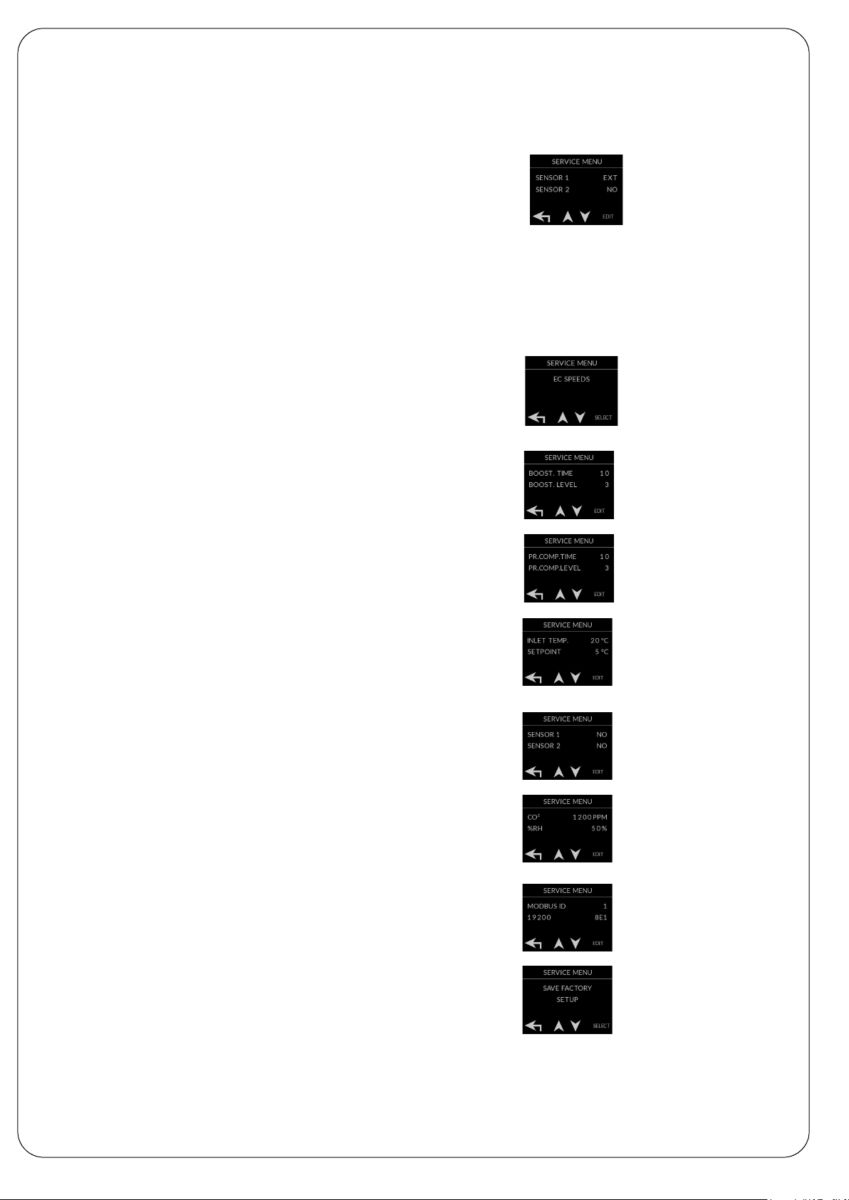
INTRODUCTION OF THE AHU CONTROL PANEL
0-10V external control (0-10V hood,remote monitoring) select the deployment
SENSOR 1 "EXT" or SENSOR 2 "EXT"
External control controls the basic speed , replaces the fan speed set in the menu.
Out-of-home, overpressure and boost are in use normally.
The main screen shows the fan speed at REMOTE CONTROL and
below of it is the speed of the supply fan.
External control fan speeds
0-2V fan 0
2-5V fan 2
5-7V fan 3
7-9V fan 4
9-10V fan 5
DEFAULT SETTINGS
1. 30 %
2. 40 %
3. 60 %
4. 80 %
5. 100 %
FAN SPEED PRIORITY
Fan speed preselection is performed from the control panel service menu.
Inlet and outlet fans can be individually adjusted for five different speeds with fan speeds of 20-100%
BOOSTING FROM THE COOKER HOOD WITH CONTACT TIP INFORMATION.
Boosting time settings 0 and 5...120 min. In 0 position with different pre-data.
Boosting level settings 1...4 (the air impellers higher than basic speed), can be
adjused also from the settings menu.
Overpressure duration specification 0 and 5...20 min. In 0 position with different
pre-data.
Overpressure limit regulation 1...4 (inlet air impeller higher than outlet air impeller)
REGULATION of the INLET AIR TEMPERATURE
Inlet air temperature range 5...30 oC,
can be adjusted via SETTINGS menu
CO2 AND/or RH SENSORS ACTIVATION
CO2 AND HUMIDY PERCENTAGE SETTING
Note: set the sensor on in the settings menu
SPEED CONTROL WITH A COOKER HOOD (0-10V)

Factory setting
IN USE
Factory setting
5
o
C
Factory setting
0
o
C
THRESHOLDS FOR FREEZING PROTECTION
The preheater is switched onfrom the service menu.
The limit value of the preheater can be changed from
the service menu if necessary. The adjustment range is 0 - +10
o
C.
The limit value of the preheater must be
approx. 5
o
C higher than
the WASTE AIR COLD limit.
Temperature measurements of the preheater and
WASTE AIR COLD are measured from the waste air temperature
It is recommended to use value a minimum of 5
o
C for the
WASTER AIR COLD limit, if the preheater is not in use. When
the preheater is in use, the set value is about 5
o
C lower than the
limit value of the preheater. The adjustment range is -10 ... + 10
o
C
The preheater and freezing protection are enabled,
changes are only if needed.
CHANGES OF THE SERVICE MENU SETTINGS ALWAYS HAVE TO BE SAVED
10
The summer bypass plate control. The user of the unit can set the bypass
plate manually to SUMMER/WINTER or AUTOMATIC mode.
In summer mode the bypass plate is activated
In the automatic mode, the plate works according to outside temperature.
Set value 15...20 oC
The automatic mode has adjustment amplitude of approx 2 hours
Set value of boosting duration 0 and 5…120 min.
In 0 position with different pre
-
data.
Set value of overpressure duration time (fireplace switch) 0 and 5…30
min. In 0 position with different pre-data.
CO
2
transmitter ON/OFF switching. Setting of CO
2
upper limit.
Set value 250...1500ppm, 50ppm steps
%RH transmitter ON/OFF switching.
Setting of RH upper limit. Set value 30...80%, 5% steps
Regulating amplitude 5...20min
Regulation of inlet air afterheating set value 5...30 oC
SETTINGS ARE APPLIED VIA THE SETTINGS MENU OF THE CONTROL PANEL

INTEGRATED HUMIDY TRANSMITTER
(optional)
The humidity transmitter is active when SENSOR 2 RH
is selected in the service menu
The humidity percentage is displayed on the main menu
screen.
If the unit is eqipped with a factory-fitted extract air humidity trasmitter.
The fan speed is automatically enchanced when the humidity
exceeds the limit value.
The limit value, the adjustment interval and ON/OFF can be
selected in the SETTINGS menu under CO2 and %RH
DOOR REVERSAL EXHANGE
REMOVING THE FAN
The fans can be removed for cleaning or replacement.
Before removing the fans, remove the HR cell and filters.
When removing supply fan, remove side support (1) of the HR cell
and the heater element case (2) from the side wall and the
cover plate (3) in the front of fan.
When removing the extract fan remove side support of
the heat recovery cell (4) and the heating element case(5)
from the side wall of the HRV and the cover plate (6) in the front of fan.
Unplug the fan plug connector. The fan is pulled out of the machine.
11
1
2
3
4
5
6
Door reversal can be changed by pushing the hinge pin
e.g with narrow tip screwdriver from the machine below
or from above
.Note! if the hand of the door is turned so that hinged side is
on the supply air filter side note that the door has room
to turn 180 degrees.
The humidity transmitter also has an on / off switch

DEEKAX Air Oy
Patruunapolku 4 Puh. 0207 912550
79100 LEPPÄVIRTA www.deekaxair.fi
PURE JOY FROM INDOOR AIR !
MAINTENANCE OF TALTERI
For producing good indoor climate continuously, the air exchange systems require regular maintenance.
The metallic grease filter of stove hood must always be kept clean for fire safety reasons. Cleansing with hot
water
or dishwasher once a month is necessary. Substances suitable for machine washing may darken the
aluminium parts of the filter.
The inlet and outlet filters of Talteri must be cleansed at least twice a year.
In summertime the summer cassette plate will be set to summer mode when the external air should come in
fresh and clean.
The heat recovery cell will be pulled out of the unit and washed thoroughly in autumn just before the heating
season begins –the heat recovery will then be at its best. Check the condition of sealing and push the heat
recovery cell back to its place.
The inner painted walls of the unit are easy to clean. Check the condition of sealing, clean the outlet hose of
condensing water and make sure the water flows freely and without any obstructions.
The impellers, air exchange adjusters and thermostats are components that do not require regular
maintenance. Electrical works can be carried out only by a qualified electrician.
During the frosty period the heat recovery cell is defrozen by using the preheater. The power of the
preheater is mainly adequate to keep the heat recovery cell defrozen. In extreme conditions, if the power of
the preheater is inadequate, the supply fan power will be reduced or stopped by the freezing protection
thermostat when the exhaust air temperature drops below the set value (0
o
C). The supply fan starts when
the exhaust air temperature rises above the set value.
Under extreme conditions (humidity /harsh cold) the heat recovery element may freeze over and the anti-
freeze protection defreezing cycles are not able to defrost it. If such a case occurs, the machine has to be
stopped, opened and the cold flow stopped and the ice
given the necessary time to melt. Check the drainage
of condensing water! In case the water-lock dries out and makes pulping noise, you can pour a drop or two
of cooking oil.
In really cold weather, the head recovery unit heats the preheated inlet air with afterheating. The functionality
can be proved by comparing the temperature of inlet air to the set value of the inlet air afterheating.
The overheat protection has been activated in case the temperature has risen +90
o
C (for instance, in case
of power failure). Reset the overheat temperature by pressing the switch under the threaded contact
protection.
The channels must be checked if the impeller works but the air exchange is inadequate or the temperature
changes in the channels between the interior and the machine. Temperature changes and humidity
concentration in channels must be prevented by improving the isolation.
Table of contents
Other Deekax Fan manuals


Popular Fan manuals by other brands


Lasko
Lasko T32200 Important instructions & operating manual

Nortek
Nortek REZNOR DS-4 Series installation manual

Harbor Breeze
Harbor Breeze E-WCK44ABZ5LKS manual

Cosa
Cosa M1-5B/56 instruction manual

Modern Forms
Modern Forms Skylark Flush installation instructions

Montigo
Montigo LDVPV58 Installation operation & maintenance


