Deekax TALTERI DIVK-C140 DEMA User manual

TALTERI
DEEKAX Air Oy
Patruunapolku 4 Puh. 0207 912550
79100 LEPPÄVIRTA www.deekaxair.fi
R
AIR EXCHANGE EQUIPMENT
INSTALLATION AND USER
MANUAL
THE QUALITY GOALS OF AIR CONDITIONING COME TRUE
WITH THE RECOVERY SYSTEM
TALTERI removes used air from interior and brings in fresh air.
Humidity and impurities are exhausted through thermal recovery
unit that heats the filtered ambient air cost-effectively. The fresh
warm air is channelled draught-free and noise-free into the
premises in necessary quantities.
ENSURE THE QUALITY OF AIR EXCHANGE!
DIVK-C140 DEMA ja DIVK-C140 DEMA VKL
QUALITY TESTED

Picture 1
****
utility room
washroom
Clothing
room
bed room
living
room
OUTDOOR AIREXTRACT AIR
kitchen
SUPPLY AIR
1
2
3
56
7
4
DIVK
SYSTEM COMPONENTS
Picture 1
1 Air exchange unit......DIVK-C140 DEMA
2 Adjustment cover......DX-ULTRA
3 Exhaust air outlets.... DLVS-200/435
4 Channel noise deductor...... 200
5 Exhaust air for the system........ 200
6 Outdoor air for the system...... 200 (250)
7 Interior air supplies............
20
0
EQUIPMENT DETAILS AND TECHNICAL DATA
1 Exhaust air out.............. 200 mm
2 Outdoor air for the system .....200 mm
3 Exhaust air for the system......200 mm
4 Interior air supply........ 200 mm
5 Electricity supply
6 Main switch
7 Supply fan, adjustable……EC 166 W
8 Extract fan, adjustable.......EC 166 W
9 Heat exchanger
10 Supply air filter (F7) ISO ePM1
11 Extract air filter (G4) ISO Course>75%
12 Exhaust of condensing water 12 mm
13 Operating panel
14 Preheater Manual overheat protection 1000 W
15 Postheater Manual overheat protection 1000 W
-(VKL water battery + actuator)
16
Summer bypass appliance
DIMMENSIONS: height 950 mm, widht 900 mm,
depth 510 mm, weight 112 Kg
2
13
6
78
9
10
11 14
16
15
In the picture a right-handed model(R)
1 EXHAUST AIR
2 OUTDOOR AIR
3 EXTRACT AIR
4 SUPPLY AIR
DUCT OUTLETS
HANDEDNESS RIGHT
4 EXHAUST AIR
3 OUTDOOR AIR
2 EXTRACT AIR
1 SUPPLY AIR
DUCT OUTLETS
HANDEDNESS LEFT
200
900
510
950
OUT-
DOOR
EXHAUST
SUPPLY
200
900
510
950
OUT-
DOOR
EX-
HAUST SUP-
PLY
Talteri heat recovery system
EX-
TRACT
EXTRACT
DLVS-200/435
EXHAUST AIR
däv-200
OVEN

3
INSTALLING THE CHANNELLING
The channels for exhaust air and incoming air should be installed, if possible, in a warm space below the vapour
barrier to suspended ceilings or casing. The vapour barrier remains intact and the channels do not need heat
insulation. This also ensures that the airflow in the channels will not freeze due to poor heat insulation as well as there
will be no condensing.
Cleansing of channels also becomes easier. The outside air and exhaust air channels are isolated under warm
conditions, see the instructions.
The channels are compiled of type-approved, rubber gasket parts and winded joint channel. Disconnections will be
removed for sealing and noise reasons. Connections will be secured with closing drawstrings and channels attached
securely to the framework with mounting strings so it will persist also cleaning.
Measuring- and regulation equipment of airflow are installed to exhaust channels after noise deductors and inflow
channels before the deductors. For cleansing, a cleansing hatch should be installed.
Remember, that a good functioning channel is: measured correctly, hermetic, carefully attached, properly isolated and
with hermetic inlets!
CHANNEL ISOLATION
Since the channels are mounted to the upper base, it must be
carefully isolated so that:
humidity will not condensate on pipe surfaces, the air will not freeze
before heat has been stored, the heated incoming air will not freeze
before it is blown into interior.
The two main rules of channel isolation are:
The warm air channels are always isolated in outer conditions with at
least 10 cm of mineral wool and windscreen plating. The cold air
channels are always isolated in inside premises with 10 cm of mineral
wool and steam barrier plating, for instance AE
-chase or AIM-mat. See
the
figure
4.
CHANNELS OF OUTSIDE AND EXHAUST AIR
The outside air will be obtained through grate without an insect net.
The air inlet will be situated to as clean space as possible, far from the
refuse discharge, smokestack, ventilation outlet and exhaust air tube.
The air inlet will be located to a height of at least 2 meters from ground
on the northern side of the building, opposite side to the traffic. Due to
warm summer weather, the outlet channel has to be thermally isolated
in a loft space. Outgoing exhaust air will be channelled above the
rooftop through well-isolated channel and by 700-900mm high isolated
roof duct. (Figure 5).
Fireplaces like hearths, ovens and sauna heating systems must
have a separate isolated combustion air channels with slide cop
ing.
Figure 4
Minimum insulation thickness of
the ventilation duct ( mm)
Rafter
Blown wool
Steam barrier
Mineral wool
Figure 5
Outdoor air inlet and
exhaust
air outlet.
size of the
duct / dm3/s
100
125
160
Temperature difference between the inside
and outside of the duct
5
o
C
30
30
30
20
40
80
10
o
C
30
40
40
20
o
C
50
50
50
30
o
C
60
60
60
40
o
C
80
80
80
50
o
C
100
100
100
Mineral wool
Supply air and
transfer air vents
Figure 6
INSTALLATION OF VENTS
Income and outlet vents are installed according to the plan.
Special attention is needed while installing income vents since a
wrong
vent in a wrong place and wrong mounting will affect the air
draught and reduce satisfaction. Steam barriers are well tightened.
In saunas, the income air is channelled above the sauna stove and
outlet will be taken from underneath the sauna platform. The sauna
fans are manually adjustable.
In kitchens, the outlet appliance should be the stove hood with
adjustment plate of three positions and an airflow gauge. The exhaust
vent is operated by the means of the adjuster. The kitchen exhaust
will be attached to the air exchange unit.
In case sound isolation is needed between the separate rooms,
cushioned air transfer vents are used, figure 6. Air transfer routes in
doorways and under the doors will greatly reduce the privacy.

TALTERI
INSTALLATION
The air exchange unit is meant for warm inner facilities. Suitable installation spots are, among others, office, dressing
or household facilities and technical or warm storages. In case the temperature of the installation location is lower than
room temperature, the factory settings of the appliance must be changed to obtain faultless functioning. The unit can not
be installed into cold outer premises or garages. Exhaust of condensing water proceeds through a water-sealed joint
hose into a washing basin or “dry” floor well. Check the horizontal position of the unit and free flow of the condensing
water.
4
TALTERI
The control cartridge
DOOR
The installation of the
partition wall without insulation
and the bedroom wall
should be avoid because
of the shift of voice.
TALTERI has a built-in
condensate drain water lock.
The drain hose directly
directs the water downwards
from the rear wall of the
machine to the floor drain.
If a separate water trap is
installed, the water trap
inside the machine must
be removed.
Under the base plate there is a water lock built from condensate hose.
If an outside condensate hose lock is used, the machine´s own water lock
must be removed and make sure that the condensate hose is downward.
If the water hose is connected to a 32 mm sewer pipe imported inside the wall
it is necessary to seal the joint so that no water vapor enters the electrical
connection underneath the machine. In this case, the intake air supply must be
secured by a separate branch on the tube.
If the water hose is connected to the sewerage ring off the sink, the machine´s
own water lock must be removed and a separate water lock is to be placed
next to the sink own water trap.
Condensate hose is not recommended to be run in a water trap or floow drain
where hot wash or shower water is supplied.
After installation, check the water drainage from the condensate water pool.
The unit can be mounted on the wall using the angle lists. Fasten first M8 screws on the finished holes on the side of the machine.
When installing on the floor attach to the machine 150 mm high plinth (option) with M8 screws.
Raise from the floor give space to condensate water hose and power line.
The unit can be mounted on the roof with threaded rod or with foot plinth, which is attached to the machine finished holes on the
upper side of the machine.

5
ALARM
NC
YHT
NO
M
L
N
230 V
max.
8A
250V
NO
- machine running
NC
- machine off
- alarm temperatures
- alarm sensors
- over-temperature alarm
- machine in standby mode
VAK
NO NC
GENERAL ALARM
Spring return damper motor connection
The damper motor closes
- the machine stopped
- the machine in standby mode
- the machine alarm
The fan speed of Talteri ventilation unit can be controlled with
Ultra PC EC, PG EC, DS-600 EC and DSA-900 EC cooker hood
or 0-10 V voltage signal from Control panel.
The voltage signal connected to
CO2/%RH1
terminal.
Sensor 1(EXT) can be operated through maintenance menu
of the operating panel.
The boosting of Talteri ventilation unit can controlled with
Ultra KTS cooker hood.
There is a control panel and when the closing damper of the cooker hood
is open the fan speed is enhanced.
Maintenance menu is used to set boost 0, there can be operated the
quantity of boost too.
Input
230V,
50 Hz
10 A
-power
cord
(plug)
Operator panel
+24 0 0-10
CO2/%RH1
+24 00-10
CO2/%RH2
Boosting
0-10
Out-of-house/
Remote
+24 0 0-10
Cooling
+24 0
water radiatorFilter
+24 0
Heat recovery
bypass
winter
YHT
summer
ALARM
NC
YHT
NO
G+ G0 OUT1
CO
SENSOR
VAK
0
0-10V
COOKER HOOD
0-10v voltage signal
0
0-10V
PC EC
PG EC
Input
230V,
50 Hz
10 A
switch
KTS
NO
COM
NC
open
closed
max.
8A
250V
sensor 1 sensor 2
VS+ GND RH
switch
switch
MODBUS
A/D+
B/D-
0
MODBUS
O O O
O O O
O O O
ON OFF BIAS B
ON OFF Term
ON OFF BIAS A
NC
YHT
NO
max.
8A
250V
ALARM
ALARM INDICATION
AND OPERATING
POTENTIAL FREE CONTACT
INFORMATION MACHINE
OR
SPRING RETURN DAMPER
MOTOR CONTROL
ELECTRICAL CONNECTIONS
Electrical connections must be done following the installation manual
and wiring diagram.
ELECTRICAL CONNECTIONS CAN BE DONE ONLY BY
AN ENTREPRENEUR WITH RESPECTIVE INSTALLATION RIGHTS.
The electrical connection box opens from the bottom of the machine
(from below) by removing the screws.
The electrical connection box is displayed by pulling it up to its limit.
Supply voltage can be connected by contact plug.
The control panel is connected to the control card with a modular
connector.
The following can be connected as accessories:
- Carbon dioxide transmitter;
- Humidity transmitter;
- Separate overpressure or Extended time switch
(pulse switch);
- Separate Boost switch (pulse switch);
or setting off as pre-data (for instance,
sauna oven, stove hood);
- Remote control or out-of-home switches
(pre-data);
- Differential pressure switches for filters;
- External speed control 0-10V.
- Modbus.
The functions can be operated through
maintenance – and setup menus of the operating
p
a
nel.
Overpressure/
extended
HUMIDITY
TRANSMITTER
Pulse
switch
Pulse
switch
Pressure
switches
cooling
coil
actuator
DC 24 V
0-10v
Overpressure
setpoint 0
tip of the data in
boosting
setpoint 0
tip of the data in
COOKER HOOD
with boosting information
2
VAK

6
C 140 DEMA VKL
KS KS
T1 T2 T3 T4 T5 T6
OUT-
DOOR
SUP-
PLY
EX-
TRACT
EX-
HAUST
WA-
TER
PRE-
HEATER
POST-
HEATE R
CONTROL
PANEL
230VAC
L N PE
FUSE
TEMPERATURE SENSOR
+24 0 0-10
CO2/%RH1
+24 00-10
CO2/%RH2
OVE R PR ESSU R E/
EXTE NDE D TI ME
BOOSTING
0-10
OUT-O F-HOUSE /
REMO TE
+24 0 0-10
COOLING
+24 0
WATER RADIATOR
FILTE R
+24 0
HEAT RECOVERY
BYPA SS
WINTER
YHT
SUMM ER
ALARM
NC
YHT
NO
Circuit board
ECU
R
EXTRACT SUPPLY
0-10 0-1 00 0
SUPP LY/EXTRACT
N NU U
TRIAC
PREH.
SUPPLY
FAN
EXTRACT
FAN
N3 2 1
K
S
N3 2 1
KS
N3 2 1
K
S
N3 2 1
K
S
N
4
L
1
L
2
N
3
L
N
Input
230V,
50 Hz
10 A
-power
cord
(plug)
( IU )
E
J
PRE-
HEATER
50c 90c
1000W
1
-
2
+
3
+
Belimo LM 24
Summer bypass
230 N
24
0
Transformer
230/24
0-10v
0v
24vac
red
blue
black
2A 1A 5B 4B
SWITCH
ON-OFF
WATER RADIATOR
ACTUATOR
0-10v
0-10v
0v
24vac
C 140 DEMA
KS KS
T1 T2 T3 T4 T5 T6
OUT-
DOOR
SUP-
PLY
EX-
TRACT
EX-
HAUST
WA-
TER
PRE-
HEATER
POST-
HEATER
CONTROL
PANEL
230VAC
L N PE
FUSE
TEMPERATURE SENSORS
+24 0 0-10
CO2/%RH1
+24 00-10
CO2/%RH2 OVERPRESSURE/
EXTENDED TIME
BOOSTING
0-10
OUT-OF-HOUSE/
REMOTE
+24 0 0-10
COOLING
+24 0
WATE R RADIAT OR
FILTER
+24 0
HEAT RECOVERY
BYPASS
WINTE R
YHT
SUMMER
ALARM
NC
YHT
NO
Circuit board
ECU
R
EXTRACT SUPPLY
0-10 0-100 0
SUPPLY/EXTRA CT
N NU U
TRIAC PRE-
HEATER
TRIAC
POST-
HEATER
SUPPLY
FAN
EXTRACT
FAN
N3 2 1
K
S
N3 2 1
KS
N3 2 1
K
S
N3 2 1
K
S
N
4
L
1
L
2
N
3
L
N
Input
230V,
50 Hz
16 A
-power
cord
(plug)
( IU )
E
J
POST-
HEATER
50c 90c
PRE-
HEATER
50c 90c
1000W
1000W
1
-
2
+
3
+
Belimo LM 24
Summer bypass
2A 1A 5B 4B
SWITCH
ON-OFF
MODBUS
A/D+
B/D-
0
O O O
O O O
O O O
ON OFF BIAS B
ON OFF Term
ON OFF BIAS A
MODBUS
A/D+
B/D-
0
O O O
O O O
O O O
ON OFF BIAS B
ON OFF Term
ON OFF BIAS A

Water heater (VKL) Talteri installation is equipped with a note
- The desingn must take into account the water temperatures used and chech the adequacy of the
the heating power under the design conditions.
- The afterheating coil is connected inside the machine with a copper or similar plastic tube
- The water entering the machine must be pre-adjusted after the boiler.
- The water entering the heating coil is connected to an actuator (3/8 internal spiral) that adjusts the water flow
to the heating coil.
- The return water is connected with 10 mm pressing connector and the vent valve is installed at the highest point.
- Both the supply and return pipes are fitted with shut-off valves
- A safety device in case of power failure will be open-air duct of the horizontal part
install a spring-loaded damper motor or spring closing damper, which prevents air flow through the machine
when its wind pressure and the freezing of the water battery. Damper axle must be in an upright position
COMING
WATER
RETURN
WATER
WATER
FLOW AIR FLOW
RISE OF THE
TEMPERATURE
TOTAL
POWER
70
o
C
70
o
C
50
o
C
35
o
C
35
o
C
50
o
C
40
o
C
34
o
C
28
o
C
24
o
C
23
o
C
22
o
C
108 l/h
108 l/h
108 l/h
108 l/h
108 l/h
108 l/h
80 l/s
50 l/s
120 l/s
80 l/s
120 l/s
60 l/s
-5/30
-5/38
-5/23
-5/21
-5/21
-5/27
4,1 kW
1,7 kW
1,9 kW
3,7 kW
3,1 kW
5,0 kW
The water heater capacity dimension table
900
DIVK-C140 DEMA VKL R (right-handed)
900
DIVK-C140 DEMA VKL L (left handed)
7

8
INTRODUCTION OF THE AIR EXCHANGE
SYSTEM
BEFORE OPERATING YOUR AIR EXCHANGE SYSTEM,
MAKE SURE THAT:
- There are no loose objects within the unit or the air impeller;
- The coverings of construction-time are removed from
the outlet- and exhaust air holes;
- All isolations and steam barriers are in order;
- The heat transfer and fans are in their places;
- The condensing water outlet is installed and the water
is drained out;
- The air impellers and their adjusters are in working order;
- Afterheating is regulated and working.
USAGE DURING INSTALLING
The air exchange unit should be started as soon as
installation permits.
Efficient air exchange promotes drying of the constructions
and prevents damage.
In case channelling has not been completed, fans and adjustments
are missing,filter paper must be used in place of fans to keep
the channels clean andprovide sufficient counterpressure for
preventing overload. The unit must be used with full power and
check the drainage of the condensing water.
The appliance, filters and heat exchangers must be cleaned
and the systemadjusted after the construction works are
completed.
BASIC ADJUSTMENT OF AIRFLOW
The unit alone can not produce good interior ear in case
the channels and fans are installed carelessly and main
adjustments are not made.
Regulate the inlet and outlet fans to the planned positions
and start the unit at design power speed. Measure the airflow
in outside- and exhaust air channels.
The outlet must be 5-15% higher than inlet. Check the
pressure level of thechannels by checking from the fans and
adjust it accordingly to obtain the pressure level of 10-30 Pa
for fans; adjust and lock the pattern.Draw measuring- and
adjustment records!
USAGE AND CORRECT LEVEL OF AIR EXCHANGE
The air exchange level is regulated by changing the
working speed of the air impeller from the operating panel.
Airflow of different adjustable positions can be seen
from page 8.
Adjustable position 1 is for basic air exchange for an empty house.
Adjustable position 2 and 3 are normal working positions.
Adjustable position 4 and 5 are efficiency positions (i.e. for saunas).
The correct usage positions will be found by experience;
observing the purity of the air or sultriness when coming in
from outside, observing moisture on the windows or drying
of the sauna.
AFTERHEATING AND SUMMER BYPASS OF INLET AIR
The unit is equipped with 1000W electrical battery operated
by the means of triac-adjuster or a water battery (VKL) operated by
the operating device for afterheating the heat recovered inlet air.
The temperature of inlet air is usually regulated to +17C.
The temperature may be adjusted to higher during winter so there
would be no draught like feeling. In cas
e of severe frost and
efficiency mode the heating power might turn out insufficient –
in such circumstances, the air exchange should be reduced.
The overheating protection launched during malfunctioning
must be annulled manually.
During summertime, the Ito-exchanger element on the bypass plate
will be closed so the exhaust air will not warm up the inlet air.
50
100
150
200
250
300
350
20 40 60 80 100 120 140
20%
90%
100%
Air flow
dm3/s
Paine-ero koneen yli
Pa
1.
2.
4.
5.
80%
70%
3.
60%
50%
40%
30%
EXTRACT AIR
DIVK C-140 DEMA air flow
400
450
Paine-ero koneen yli
SUPPLY AIR
160
50
100
150
200
250
300
350
20 40 60 80 100 120 140
20%
90%
100%
Air flow
dm3/s
Pa
1.
2.
4.
5.
80%
70%
3.
60%
50%
40%
30%
400
450
160
EC speeds preselection is performed from the control panel maintenance menu.
Inlet and outlet fans can be individually adjusted for five different speeds with fan
speeds of 20-100%
THE SUMMER BYPASS OF THE UNIT MUST BE IN THE WINTER POSITION WHEN THE AIR FLOWS ARE BEING ADJUSTED

9
Changes of the MAINTENANCE menu settings alwasy have to be saved.
.
Factory setting
10 min
3
Factory setting
17
o
C
MODBUS MENU
Check the separate Modbus manual
SEPARATE FIREPLACE SWITCH OR PRESSURE COMPENSATION
Factory setting
10 min
1
SERVICE MENU
SETTINGS
Note: swipe right at
the top of the screen
INTRODUCTION OF THE AHU CONTROL PANEL
Settings are applied via the service menu
0-10V external control (0-10V hood,remote monitoring) select the deployment
SENSOR 1 "EXT" or SENSOR 2 "EXT"
External control controls the basic speed , replaces the fan speed set in the menu.
Out-of-home, overpressure and boost are in use normally.
The main screen shows the fan speed at REMOTE CONTROL and
below of it is the speed of the inlet fan.
External control fan speeds
0-2V fan 0
2-5V fan 2
5-7V fan 3
7-9V fan 4
9-10V fan 5
DEFAULT SETTINGS
1. 30 %
2. 40 %
3. 60 %
4. 80 %
5. 100 %
FAN SPEED PRIORITY
BOOSTING FROM THE COOKER HOOD WITH CONTACT TIP INFORMATION.
Intensification time settings 0 and 5...120 min. In 0 position with different pre-data.
Intensification limit settings 1...4 (the air impellers higher than basic speed)
REGULATION of the INLET AIR TEMPERATURE
Inlet air temperature range 5...30 oC,
can be adjusted
v
ia
SE
TTINGS
menu
CO2 and/or RH SENSORS ACTIVATION
CO2 AND HUMIDY PERCENTAGE SETTING
Note: set the sensor on in the settings menu
Overpressure duration specification 0 and 5...20 min. In 0 position with different
pre-data.
Overpressure limit regulation 1...4 (inlet air impeller higher than outlet air impeller)
Fan speed preselection is performed from the control panel service menu.
Inlet and outlet fans can be individually adjusted for five different speeds with fan speeds of 20-100%
0
-
10V SPEED CONTROL WITH COOKER HOOD

10
LED OPERATION REASON
BLINGIN RED
RED
YELLOW
GREEN
SENSOR FAULT
RETURN WATER GOLD
INCOMING AIR GOLD
INCOMING AIR HOT
FILTER PRESSURE-
CAP SWITCH
MAINTENANCE INTERVAL
REMINDER
OUT-OF-HOUSE SWITCH
OVERPRESSURE ACTIVATED
INTENSIFICATION ACTIVATE
co2/RH INTENSIFICATION ACTIVATE
PRE-HEATING ACTIVATE
AFTERHEATING OR
AFTERCOOLING ACTIVATED
-
HUMIDITY AND CARBON
DIOXIDE VALUE
IF SENSORS ARE INSTALLED
(accessory equipment)
BLINGIN YELLOW
BLINGIN GREEN
ACTIVATING/DEACTIVATING OVERPRESSURE or (EXT.TIME), INTENSIFICATION AND
AFTERHEATING
OPERATING PANEL USER INSTRUCTION
MAIN DISPLAY AND ADJUSTMENT OF BLOWING SPEED
EDIT
FUNCTIONS
RETURN
EDIT
SET
SET SET
Touch screen buttons:
Boosting
Fireplace switch
(pressure compensation)
Out-of-house mode
Fan speed adjustment 1....5
SET
EDIT
EDIT
EDIT
The button can be used to browse
the menu upwards and change settings.
The button can be used to browse
the menu downwards and change setting value.
Return to the previous or main menu.
CLOCK
THE DISPLAY ALSO
SHOWS POSSIBLE
INCREASED EFFICIENCY AND
MALFUNCTIONS
TEMPERATURE DISPLAY FOR
TEMPERATURE OFOUTSIDE AIR,
INCOME AIR, OUTLET AIR AND
EXHAUST AIR
ACCURACY OF TEMPERATURE
SENSORS
+
1
o
C

11
Selecting language suomi, svenska, english or eesti
SETUP MENU
Maintenance interval and reset
Display sensor and overheating faults,
temperature deviations, filter exchange and starts
Fault list reset
Air exchange can be reduced/increased during selected time periods.
5 different periods can be programmed. Each time period can be set for one or several weekdays.
In office-mode, the unit stops for the period out of selection and display reads standby.
Weekday and clock selection
CO2 transmitter ON/OFF switching.
Setting of CO2 upper limit.
Set value
25
0...1500ppm, 50ppm steps
Regulation of inl
et air afterheating set value
5...30
o
C
SETTINGS
Fan speed adjustment 1....5
%RH transmitter ON/OFF switching.
Setting of RH upper limit.
Set value 30...80%, 5% steps
Regulating amplitude 5...20min
Touch screen buttons:
Boosting
Fireplace switch
(pressure compensation)
Out-of-house mode
Fan speed adjustment 1....5
The button can be used to browse
menu upwards and change settings.
The button can be used to browse
menu downwards and change setting value.
Return previous or main menu.
The summer bypass plate control. The user of the unit can set the bypass plate manually to
SUMMER/WINTER or AUTOMATIC mode
In summer mode the bypass plate is activated
During the automatic mode, the plate works according to outside temperature. Set value 15...20 oC
The automatic mode has adjustmen
t amplitude of approx 2 hours
Set value of intensification duration
0 and 5…120 min.
In 0 position with different pre
-
data
.
Set value of overpressure duration t
ime
(hearth switch) 0 and 5…30 min.
In 0 position with different pre-data.
.

12
MAINTENANCE MENU
Return to default settings.
Note VLK’s units post-heating fuction must be switched
on
from th
e service
menu
Startup with remote control or separate switch;
“remote control ON” the unit operates only
if pre-data is switched on
OR
Out-of-house mode
“Remote control off” the unit operates on
minimum speed with pre
-
data switched on
Usable if the differential-pressure switch is present
Maintenance interval reminder settings 0
-
12 months
NOTE!:SWIPE RIGHT AT THE TOP OF THE SCREEN
SETTINGS
HOME overpressure activated
OFFICE continuation time activated
Modbus
Touch screen buttons:
Boosting
Office-mode
(extended time)
Out-of-house mode
Fan speed adjustment 1....5
The button can be used to browse
menu upwards and change settings.
The button can be used to browse
menu downwards and change setting value.
Return previous or main menu.
Inlet air cooling temperature
-
10...15
o
C
Inlet air heating temperature 30...40
o
C
CO2 and/or RH sensors activation
The external control 0-10 V activation
Office-mode continuation time setting
30…120 min. Usable with a separate
pulse-switch if the weekly clock is used
in office-mode.
CO2 and humidity percentage setting
Changes of the
SERVICE
MENU
settings always have to be saved

13
F
reeze
-
alert
settings
-
10…
10
o
C
Anti
-
freeze appliance’s control
Pre
-
heating activation
Regulation of VKL-appliance’s
water battery backup-sensor
Set values 0 and
5...10
o
C
, O
–
deactivated
Afterheating selection
ELECTRICITY or WATER
Regulation of Inlet Air and Pre-heating value
The value of pre-heating should be regulated
to be approx 5c higher than the
limit of cold exhaust air
Overpressure duration specification 0 and 5...20min.
In 0 position with different switch pre-data
Overpressure limit regulation 1...4 (inlet air impeller
higher than outlet air impeller)
Intensification time settings 0 and 5...120min. In 0
position with different switch pre-data.
Intensification limit settings 1...4 (the air impellers
higher than basic speed)
BACKLIGHT BRIGHTNESS AND STANDBY SCREEN
Adjustment of backlight
Press and hold the FUNCTIONS for about 5 seconds
Options : not in use, time and temperatures
EC speeds preselection is performed from the control
panel maintenance menu.
Inlet and outlet fans can be individually adjusted for
five different speeds with fan speeds of 20
-
100%
Changes of the SERVICE MENU
settings always have
to be saved

14
1. Operating panel
The operation is directed according to settings inserted by the user or installer/manufacturer th
rough the operating panel
as well as according to temperature sensors and set periods.
The operating panel returns from processing state to basic state 2 minutes
after the last button pressing. The return time
from normal position is 2 minutes.
Maintenance menu – for setting suitable parameters for the installation. Maintenance menu is hidden from the end-
user.
“Restoring factory settings” option is also present in the maintenance menu that can be used for turning all settings to
default settings.
The user can use four different selections on the operating panel: weekday and time with the shortcut icons, blowing
speeds, temperatures and air quality values in case there are sensors for these functions.
2. Operating card
The controller card controls the operation of the device user's choices and measurement data from the sensors Received
by. The controller card is
in addition to two transmitter inputs Which can be connected% RH or CO2
transmitter. The card has an additional 4 pcs
switch data inputs and two
EC - a five-speed fan outputs. The control panel is connected to the controller card, a modular six-pole.
3. Controlling of the air impellers
3.1. Speed controlling in default state
The supply and exhaust air controlled 5 speed. Maintenance menu can be selected fans (20-100%) are suitable for
speeds of the subject. The fan speeds are individually user selectable. At speeds in the service menu is the default
setting which the machine starts.
3.2. Overpressurization
Overpressurization state selectable from the outer switch or operation panel. Outlet impeller runs at basic speed, inlet
impeller is set to value of the maintenance menu. The intensifications have no impact at this point. The duration of
overpressurization in minutes is selectable by the user. New push from the switch launches overpressurization from the
beginning. Overpressurization can be shut down also from operating panel. Anti-freeze is deactivated when
overpressurization is switched on.
3.3. Intensification
Intensification of air exchange can be activated from the operating panel or stove hood. Activation from the panel sets
the durability of intensification in minutes (5...120min). Maintenance menu is used to set the quantity and default time.
In this case, CO2/%RH intensification has no impact. Intensification is activated also according to external data.
3.4. CO2- and %RH- intensification
CO2 – transmitter or data given by the transmitter is the basis for air exchange intensification in regulating intervals.
The CO2 maximum limits are set from the panel by the user (250…1500ppm, 50ppm steps). CO2
measuring values can
be seen on the operating panel. The air exchange is periodically intensificated by data of %RH – transmitter or
transmitters. The maximum limits of relative humidity are set from the panel by the user (30…80%, 1% steps). %RH
measuring values can be seen on the operating panel. The card has two transmitter inputs that can be chosen separately
for CO2 or %RH activation and deactivation. Regulation interval is a parameter set through the maintenance menu that
determines how often the impeller speed can change in intensification mode. Set value 5…20 minutes by 1
minute. The
regulation interval is same for both CO2- and % RH intensification.
3.5. Out-of-house function
The “out-of-house” function can be selected from the external switch or from the operating panel. The impellers are set
on minimum speed. However, pr
eviously set intensification or overpressurization will be completed before the impeller
speed is reduced or stopped altogether.
3.6. Weekly clock
The program selectable by the user enables to reduce/increase air exchange during selected periods of time. 5 different
time periods can be programmed at the same time. Each time period can be set with one or several weekdays.
OPERATIONAL DESCRIPTION

15
3.7. Office mode
The installer can select the office mode from the maintenance menu – this is useful in case the air exchange system is installed
into an office where activities take place mostly during daytime.
The mode is equipped with continuation switch that enables persons who remain in the office for longer to prolong the
functioning of the appliance by set interval. Intensification and out-of-house mode functions are not usable in the office mode.
Remote control mode can also be selected from the maintenance menu that enables to switch the unit on and off by the mean of
pre-programmed data and weekly clock functions are deactivated.
4. Setting the temperature
Temperature is measured from four different sources: temperature outside, inlet temperature, outlet temperature and exhaust air
temperature. The temperatures are displayed on the operating panel. The precision of measurement is +/- 1 degree.
4.1. Afterheating
The thermostat leads the afterheater located in the inlet channel. The heater can be electrical or water heater and is selected by the
installer from the maintenance menu. The heater keeps inlet air at the exact temperature selected by the user. The desired
temperature can be set from the operating panel. Set values are between 5 – 30 d egrees.
4.2. Preheating
Preheater is an electric heater located in the outlet channel. The preheater´s thermostat is driven based on the temperature of
exhaust air. Preheating is meant for prevent freezing of the recovered heat. The temperature setting of the thermostat can be
selected by the installer from the maintenance menu with limitations of 0 – 10 degrees.
4.3. Summer cassette function
The unit is eq uipped with summer cassette for heat exchange during summertime. The user can select the function manually or let
the functioning be determined automatically according to the temperature outside. During the Summer-mode, the bypass plate of
the cassette is activated. The automatic fu nctioning can be set with external temperature between 15 – 20 degrees.
5. Alarms and reminders
5.1. Activation of overheat protection
Information on activation of overheats protection connected to electrical afterheater and preheater is received from the heater. In
case the protection launches, the impellers are automatically set on minimum speed, red indicator light blinks on the operating
panel and the display informs about malfunctioning.
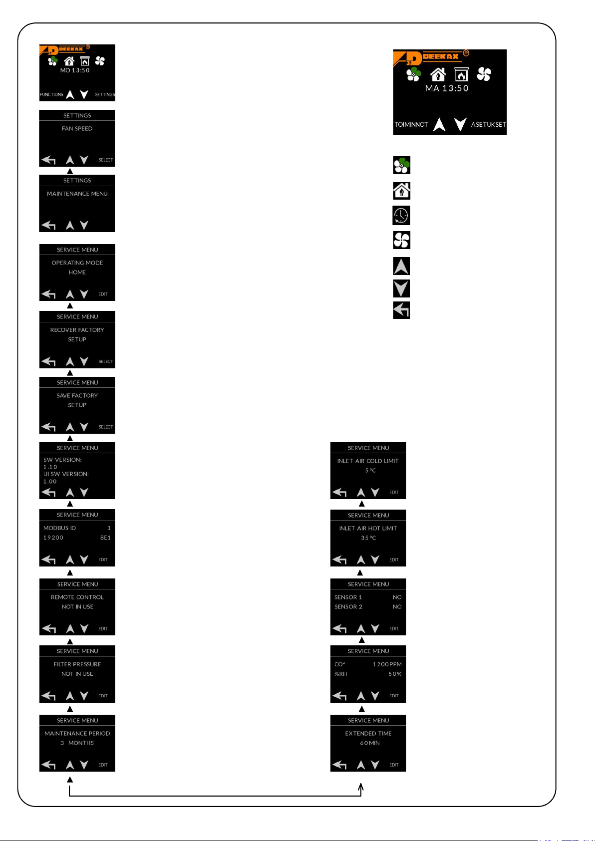
5.2. Inlet air too cold
Inlet air minimum temperature must be set from the maintenance menu. When the air temperature is lower than set, the
information will be d isplayed on operating panel and red indication light is turned on. The inlet impeller is stopped and the speed
of outlet impeller is reduced to minimum. These actions prevent the water-circulation battery from freezin g.
5.3. Income air too hot
Maximum limit of income air temperature must be set from the maintenance menu. When the air temperature exceeds the set
limits, respective information will be displayed on operating p anel and red indication light is turned on. The inlet impeller is
stopped and the speed of outlet impeller decreased to minimum.
5.4. Exhaust air too cold
The exhaust air temperature minimum limits must be set from the maintenance menu (-10 … 10 degrees). When the air
temperature is lower, warning is displayed on the operating panel and red indication light is turned on. The temperature is
attempted to keep above the set value by reducing the speed of inlet air impeller (see also preheating) by regulating it one-
step at a
time. In case the air temperature does not rise over the alarm limit even when the impeller is completely stopped, the red
indication light starts to blink and freezing alert is displayed . In case the temperature is restored to normal, normal functioning
will be also restored by increasing the impeller speed one-step at a time.
5.5. Danger of water battery freezing
In VKL machines can be set the temperature of the water radiator from the service menu “radiator return min temp”
and when the value falls down, a notification is displayed and the red indicator lights up in the control panel. The inlet
fan is stopped.
5.6. Alarms for remote monitoring
General alerts may be taken into the remote control from potentially free relay. Alarms are obtained inlet air hot or
cold, danger of water battery freezing, overheat protectors and if the machine is stopped.
5.7.Maintenance interval reminder When the maintenance interval is complete, the respective informatio n is
displayed on the operating panel and the indication light blinks green. The user can reset the reminder after the filters have been
changed. The maintenance interval counter is reset and the new alert will be transmitted after the period has b een completed
again. The maintenance interval can be set between 3 – 12 months.
5.8. Filter-dirty notice Differential pressure s
witch can be installed to the equipment that measures dirtiness of the inlet air
filter by monitoring its differential pressure. When the switch runs, the display transmits the necessity of filter-change and the
indication light blinks yellow. Differential pressure switch is taken into use through the maintenance menu and it deactivates
maintenance interval reminder indication light blinks yellow. Differential pressure switch is taken into use through the
maintenance menu and it deactivates maintenance interval reminder

DEEKAX Air Oy
Patruunapolku 4 Puh. 0207 912550
79100 LEPPÄVIRTA
PURE JOY FROM INDOOR AIR !
MAINTENANCE OF TALTERI
For producing good indoor climate continuously, the air exchange systems require regular maintenance.
The metallic grease filter of stove hood must always be kept clean for fire safety reasons. Cleansing with hot
water dishwasher once a month is
necessary. Substances suitable for machine washing may darken the
aluminium parts of the filter.
The inlet and outlet filters of Talteri must be cleansed at least twice a year.
In summertime the summer cassette plate will be set to summer mode
when the external air should come in fresh and clean.
The heat recovery cell will be pulled out of the unit and washed thoroughly in autumn just before the heating
season begins –the heat recovery will then be at its best. Check the condition of sealing and push the heat
recovery cell back to its place.
The inner painted walls of the unit are easy to clean. Check the condition of sealing, clean the outlet hose of
condensing water and make sure the water flows freely and without any obstructions.
The impellers, air exchange adjusters and thermostats are components that do not require regular
maintenance. Electrical works can be carried out only by a qualified electrician.
During the frosty period the heat recovery cell is defrozen by using the preheater. The power of the
preheater is mainly adequate to keep the heat recovery cell defrozen. In extreme conditions, if the power of
the preheater is not sufficient, the supply fan power will be reduced or stopped by the freezing protection
thermostat when the exhaust air temperature drops below the set value (0°C). The supply fan starts when
the exhaust air temperature rises above the set value.
Under extreme conditions (humidity /harsh cold) the Ito-element may freeze over and the anti-freeze
protection series are not able to defrost it. If such a case occurs, the machine has to be stopped, opene
d and
the cold flow stopped and the ice given the necessary time to melt. Check the drainage of condensing water!
In case the water-lock dries out and makes pulping noise, you can pour a drop or two of cooking oil.
In really cold weather, the head recovery unit heats the preheated inlet air with afterheating. The functionality
can be proved by comparing the temperature of inlet air to the set value of the inlet air afterheating.
The overheat protection has been activated in case the temperature has risen +90°
C (for instance, in case of
power failure). Reset the overheat temperature by pressing the switch under the threaded contact protection.
The channels must be checked if the impeller works but the air exchange is inadequate or the temperature
changes in the channels between the interior and the machine. Temperature changes and humidity
concentration in channels must be prevented by improving the isolation.
This manual suits for next models
1
Table of contents
Other Deekax Fan manuals
Popular Fan manuals by other brands

Vortice
Vortice CA-V0 Instruction booklet

Adler
Adler AD 7319 user manual

System air
System air KBR 315D2 IE2 Installation and operating instructions

Ebmpapst
Ebmpapst W3G560-GQ41-01 operating instructions

Ebmpapst
Ebmpapst R3G450-AQ25-68 operating instructions

minkaAire
minkaAire Xtreme Instruction manual warranty certificate

Gulf Coast Fans
Gulf Coast Fans 4YU26 owner's manual

jbc
jbc FAE070 instruction manual

System air
System air Sense SNX Installation,operation and maintenance instruction

Ebmpapst
Ebmpapst A4D400-AP12-01 operating instructions

BLACK DECKER
BLACK DECKER BXEFT46E manual

Suntec Wellness
Suntec Wellness Klimatronic CoolBreeze 9.500 Tri-Vario TV+ user manual