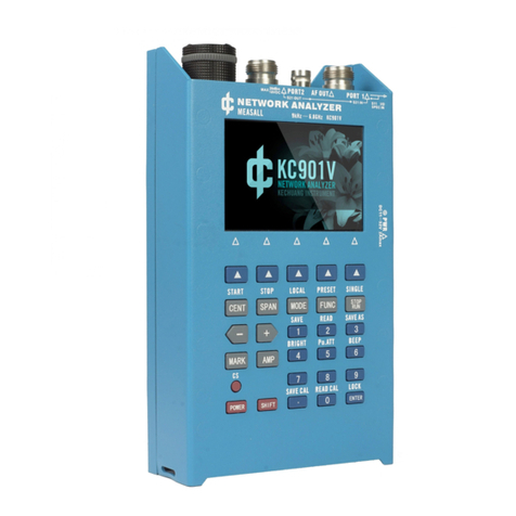
Deepace KC908 User manual

1. Introduction
KC908 is a wide-band sweep receiver, it is capable of measuring radio
frequency spectrum and field strength as well as demodulating and
monitoring common signals. As for uncommon signals, KC908 can record the
raw IQ signal and save for later analysis.
KC908 is based on SDR theory. Different from other SDR receivers, KC908
integrates complete digital signal processing unit and user interface, so there
is no need to depend on a computer. KC908 supports SDR software like
HDSDR and is able to connect with GNURadio.
As a reconnaissance equipment, KC908 is capable of sweeping swiftly and
discovering signals. Being different from traditional sweeping spectrum
analyzer, KC908 obtains spectrums of certian width using FFT and then splice
them together to acquire a panorama. In this manner, KC908 reaches a speed
of 3GHz bandwidth per-second with a 10kHz precision, which is equivalent to
120,000 25kHz channels. As for specific radio stations within 300-500MHz, it
takes less than 0.1 second to finish. We're proud of such a decent
performance on a micro-size hand-held equipment.
KC908(10.8/18.6GHz model) comes with 2 receiving channels. It can
measure the amplitude difference and phase difference between two channels.
Also, it it equipped with signal generating function to output the CW and

simple modulated signals. With GNURadio connected, KC908 is even capable
of outputing relatively complicated digital modulating signals.
1.1 Theory
KC908 contains a zero IF receiver, covering a range of 0.75-6ghz.(The left
port's range is 0.5-6Ghz). By mixing, the frequency outside this mentioned
range is moved to the range of 0.75-6ghz. The zero IF receiver samples the
baseband directly to get the digital IQ signal. The bandwidth of digital IQ
signal is 40MHz, spectrum result can be obtained by FFT. Because baseband is
generated by analog mixer, local oscillation leakage can not meet the high
requirement of spectrum analysis. In order to solve this problem, the
instrument discards a sideband and poor performance part of the FFT result
and only takes 15MHz width to display, which is the origin of effective real-
time bandwidth (15MHz). If the sweep span is wider than the effective real-
time bandwidth, the LO scans the whole sweep width with 15MHz intervals
and splices the results.
Since the spectrum is generated by splicing FFT results, the display effect,
as well as certain concepts, would definitely differ greatly from conventional
sweeping spectrometers. RBW, resolution bandwidth, for example, no longer
means the bandwidth of resolution filter. Instead, it means the equivalent

resolution bandwidth of the windowed FFT result. Limited by the computing
power, RBW can only be set within a certain range under a certain sweeping
bandwidth. As for time-varying signals that are larger than the real-time
bandwidth, the amplitude on the splicing point could possibly leap due to the
fact that those two sides of the splicing point are sampled at different
moments. What's more, the shape of the signals could be quite different from
those in the conventional sweeping spectrometer. Take the spectrums of
modulated signals as an instance, what KC908 displays is the peak value (or
average value, according to the setting), without the "illusion", which is caused
by the concept of sweeping from left to right, that at any moment only one
frequency can be swept. For this reason, the experience of analysing signals
on a traditional spectrometer, which is mostly abstracted from those
"illusions", may not work anymore.
From another persepective, real-time spectrometer does not necessarily
represent the "truth". The fact is there is a limit for the time resolution. In
other words, even there is some sort of machine that are capable of achieving
10k FFT/s, no monitor can match this speed, let alone human eyes to catch up
with that monitor. It's believed that no matter what amount of data is to be
dealt with, there will always be some kind of method to abstract the essence in
it and present those essence within a budget of several dozens of data frames.
This process is known as "detection". The detection mode setting is to set the
rule to which the abstracting process is made according. Options are like

extracting the peak value of each frequency point frame by frame, or
averaging the results of all the frames. In this manner, the result shown on the
display no longer represents the instantaneous situation of the signal, thus it's
no longer the "truth". As a matter of fact, the "truth" of a varying signal can
only be described with a time domain waveform or a mathematical formula.
Why? Because a decent frequency resolution requires a large amount of FFT
sampling points (like, 2048) to achieve, and during the sampling and
processing time, the original signal has probably changed. Yet, compared to
the sweeping spectrometer, normally the real-time spectrometer is much
closer to the "truth".
What's more, there is a limit for frequency resolution of displaying, as well.
Each frame of FFT produces more than a thousand data points, and with
splicing, these data points can even reach a magnitude of hundreds of
thousands. Due to the fact that the maximum displaying capability of KC908's
horizontal axis is 800 pixels, each pixel has to represent multiple frequencies.
How to define "represent" is another major concern of detection. In KC908,
the solution is displaying the peak value of all those frequencies a single pixel
represents, to ensure no signal is missed, which is the basic principle a
reconnaissance equipment should live up to. However, this method of
presentation may make certain frequency/phase modulated signals look like
stable signals. Thus, while analysing a single signal, it's advised to reduce

frequency span and change the dectection method to "Sample" to mitigate
this confusion.
Due to the wide frequency coverage, in order to avoid the receiver's
overload caused by the total energy of external signals and improve the anti-
interference performance, there are several pre-selectors in the front end of
KC908. The pre-selector segmentation methods of the two ports are different,
and the anti-interference performance of the two ports in different frequency
bands will vary. The specific technique will be described later. Although a large
part of RF circuits' proportion are preselectors, they can only perform rather
preliminary filtering due to the size of the instrument. Therefore, if it is used in
complex interference environment, some external filters should be used.
Digital signal processing is implemented by FPGA and MCU. While
demodulating the signal, FPGA converts the digital IQ signal again for strict
filtering. The demodulation bandwidth of KC908 is from 150Hz to 300kHz,
which is suitable for most private network signal analysis. If wider
demodulation bandwidth is needed, USB3.0 can be used to transmit the
original digital IQ signal to the computer, and the third-party software (such
as GNUradio) can be used for processing. The bandwidth of IQ signal can up
to 40MHz.
1.2 Basic Function
1. Spectrum analysis

2. Field strength measurement
3. Simple signal generator (10.8/18.6GHz model only)
1.3 Useful Functions
1.Better than 15KHz frequency measurement accuracy with any sweep span, a
single measurement can get the accurate frequency.
2.Comfortable monitoring with multiple squelch mode
3.Automatically log strong signals for reconnaissance
4.Storing up to 999 channels
5.Waterfall figure display
6.Record IQ and audio to TF card
7.Level tone function for tracing on foot
8.Analogical demodulation with high volume audio for noisy environment
1.4 Application
KC908 can be used as a traditional spectrum analyzer. It's also the ideal
choice for digital, pulse or unstable signals(like magnetron output) .
1.Professional communication engineering
2.IoT project

3.Interference searching
4.Concealed signal source searching
5.Electromagnetic radiation measurement
6.Radar and satellite station
7.Radio reconnaissance and monitoring
8.Spectrum resource occupancy analysis
9.Industrial microwave engineering
10.Electromagnetic environment evaluation
1.5 Main Parameters (note 1,2)
The main design goal of KC908 is not absolute high performace, but
sufficient performance with convenience, affordability and mobility at the
sweet spot.
Item
Min value
Typical
value
Max value
Note
Frequency range
9kHz
10.8/18.6
GHz
Real time bandwidth
1kHz
15MHz
Analysis bandwidth
1Hz
2MHz
can be set to
8MHz

Demodulation
bandwidth
150Hz
300KHz
100% POI(note 3)
210us
Where
SPAN=15MHz
Level measurement
range
+20dBm
Level measurement
uncertainty
1.5dB
Receiver only
Noise floor
-120dBm
@12kHz BW, avg
Instrument noise
coefficient
13dB
With max gain
Third input Intercept
Point
-42dBm
46dBm
REF=-70dBm
REF= 20dBm
First image
suppression
50dB
60dB
IQ image suppression
50dB
Residual
response(note 4)
-110dBm
-90dBm
Port N.C
With whip
antenna
Spurious response
-50dBc
Battery life
4h
Weight
900g

Note:1. This table just shows the parameters that user are concerned about,
for detail please see the technical parameter table in the user manual.
2. Performance is measured with the right port. The receiving performace
on the left port maybe inferior to the right port.
3. We define the intercept in POI as accurate measurement.
4. KC908 will transmit EMI during the measurement. If the antenna is
close to KC908 it will receive the EMI. This parameter is measured by a 0.2m
whip antenna, 1m from the KC908 in the microwave anechoic chamber.
2.Description of instrument
This picture shows each part of KC908. The RF port is at the top of KC908.
On the left part is mainly the data port and the knob. Speaker and microphone
are at the bottom of front panel. There is no other functional port on other
sides of the equipment.

2.1 Top panel

There are 2 RF ports on the top of KC908, left port is PORT1, right port is
PORT2. Both ports support input and output. Two LEDs in the middle of two
ports are used as indicators to show witch port is selected.
Both RF ports(adopt K type positive connector, also known as 2.92
connector) support SMA standards and are mounted on the PCB directly. The
PCB, metal shell and metal cavity support the RF ports. Shield of RF ports can
withstand a 1Nm bending force for a prolonged period, yet the core pin is
much weaker, which can only withstand a 1N force or 0.02Nm torque (deem
the smaller one as the limit). And the max tightening torque is 0.7Nm, in
actual test the user just need to tighten it slightly with finger.
Attention:
SMA connector is weak, user needs to use soft cable or antenna to
connect. User should avoid dragging antenna or cable which is connected to
KC908. Disconnect the antenna or cable when KC908 is not being used, to
avoid accidental impact. User must use high quality and right size connectors
and never rotate the SMA core pin when connect to KC908.
2.1.1 PORT 1 (Left Port)
Port 1 supports 9kHz - 6GHz range input, and 9kHz-10.8/18.6GHz range
output. The output comes with necessary filtering, and 18.6Ghz model is
equipped with a synchronous tuning filter for 6-18.6GHz. The receiving

channel of PORT 1 just has simple 2 band preselector, whose range is below
500MHz and above 500MHz, respectively.
Port 1 is mainly used as an output port, it can output full range RF signals,
and the amplitude is higher.
As for 18.6GHz model, the left port is also used to connect GPS antenna.
2.1.2 PORT 2 (Right Port)
Port 2 supports 9kHz-10.8/18.6GHz range input, 80MHz - 6GHz output.
Port 2 is mainly used as a receiving port. It has 7 band preselectors, for
10.8GHz model, there are 6 bands below the 6GHz and the last band within 6-
10.8GHz. As for 18.6GHz model, 7 bands below 6GHz and 6-18.6GHz adopts
tracking preselector. The output RF signals from port 2 is relatively weaker. It
can effectively suppress the FM broadcast interference. (When receiving at 10-
15ghz, due to the lack of fine preselector, user should pay attention to the
image interference. The center frequency can be adjusted to observe the
moving direction of the spectral line and determine whether it is mirror
interference.)
Both ports have 30dB attenuator(10dB step) and 40dB variable gain
preamplifier(20dB step). The total gain of front end is 70dB, and the
output/input signal strength can be adjusted precisely.


2.1.3 Port limitation
Both ports' max input power(average) in short time is 20dBm, above this
level will damage the port.
It allows long time input level of 10dBm. But within frequency under
100kHz should be less than 0dBm to avoid unexpected damage.
For frequency above 10MHz and the attenuator set to more than 10dB,
the peak power pulse input should be less than 30dBm and its pulse width
needs to be narrower than100us time.
Attention:
Although both ports have ESD protectors, due to the wide RF bandwidth
and other reasons, the protection ability isn't very strong, which is meant for
the prevention of human electrostatic shock under normal conditions. Avoid
using or connecting to outdoor antenna in thunderstorm weather. When an
external HF antenna is connected, it is necessary to be careful of the
electrostatic hazards of the antenna. Before use, discharge the antenna. User
should avoid using the antenna in windy weather. While using large size HF
antenna, it is recommended to connect a high pass filter with DC grounding
outside to protect the KC908. It is suggested that the suppression of
frequency below 500KHz is better than 30dB.
Before connecting the circuit to be tested, user needs to contact the shield
of the connector with KC908, to make sure the circuit's electric potential
equals KC908's.

2.2 Left side panel
The KC908 has two charging ports, both of which can charge the
instrument. There is a charging indicator LED between the two charging ports.
After the charger is inserted, the indicator light shows red to indicate that it is
charging. Red light means charging slowly, while blue light means charging
rapidly. When it keeps green, it means that it is charged completely; when the
LED flashes quickly, it means that the charging fails, so it is necessary to check
the applicability of the charger.
2.2.1 12V charging port
The charging port supports 9-26v charging voltage, and the
recommended voltage is 12V. It can be directly connected to 12V, 13.8V or
24V automobile batteries. The maximum charging current of 12V charging
port can reach 2A, which can fully charge KC908 in about 3 hours.
For continuous measurement, 12V charging port should be used for
power supply, and the voltage should be 12~18V. KC908 is generally not
recommended for continuous operation all year round. If the measurement is
more than 30 days, the battery shall be removed. After removing the battery,
the external power supply must be robust enough to support the large current
(5A) at startup.

2.2.2 USB charging port
In order to reduce the burden of carrying charger, KC908 supports USB
charging, user can use ordinary mobile phone charger and "power bank" to
charge. USB charging port uses type-C connector, which supports most quick
charging protocols. The maximum charging voltage can reach 20V, and the
limit current is 3A. The charging current can be adjusted automatically
according to the voltage drop rate of the charger, so as to support most
mobile phone chargers. If the charger's output capacity is insufficient, the
charging current may be less than 500mA.
Charging time with USB charging is related to the charger. If the charger
supports quick charging protocols (PD3.0, QC3.0, UFP), it may be 2 hours. If
quick charging is not supported, it will take at least 7 hours. When charging
with power turned on, the battery power will still be consumed, just the
endurance time will be extended. When the battery is not installed, the USB
charging port cannot support the instrument to power on. We can't guarantee
the compatibility of all quick charging chargers.
No matter 12V or USB charging port is used, keep away from inflammable
and explosive materials while charging, and a person shall keep an eye on it.
When the ambient temperature is higher than 35° or the ventilation is poor,
the battery can only be charged in the power off state.

2.2.3 USB 3.0 port
This port is used to output the high speed IQ signal to host. The program
manual show the usage method.
2.2.4 USB-OTG port
This is a USB 2.0 standard port that supports OTG, and it's mainly used to
control dedicated accessories. It can also be converted to a ethernet port
using USB/RJ45 converter. Please refer to the program manual for details.
This port supports 5V@500mA output. Avoid short-circuiting this output
or pairing it with a load with a exceedingly large current.
2.2.5 KEY/DATA port
This 3.5mm port can be connected to telegraph key or automatic key to
transmit operations. It can also output control signals to control specialized
accessories like a T/R converter. This is the pin definition:

KEY1 and KEY2 are used to connect the telegraph key. While using a
manual key it should connect to KEY1 and GND. To use an automatic key user
should connect KEY1, KEY2 and GND. The driving voltage for key is usually
1.8V.
LVCMOS pin is used to output control signals. The high signal level is 3.3V
with reference to GND.
This port does not support signal input, avoid inputting a high power
signal or it may be damaged.
2.2.6 AUDIO port
This port is used to connect an external speaker or a speaker mic. The
audio through this port is amplified. The max power at 4Ohm impedance can
reach 1.5W. Early products only connect the last section of the plug to audio
power amplifier output, while recent products have altered this design to
connect the last two sections, to provide a stereo output. For this reason, the
user must pair it with a 4-section plug. DO NOT short the second section to
the ground.
Pin definition:

Those common hand speaker mic compliant to this pin definition can be
used. When using normal Condenser or Dynamic microphone, Connect the
microphone to MIC-PTT and GND then KC908 considered the PTT is pressed.
The sensitivity of microphone is about 50mV. The speaker should be
connected to the SPEAK and GND pin. When using headphone user should
turn down the volume before plugging. In KC908’s FUNC menu user can set
turn off or not the built-in speakers after plugging in this port.
This port does not support other signal input, avoid inputting a high
power signal or it may be damaged.
2.2.7 Knobs
KC908 has two knobs on the left side. The upside one is a multifunctional
knob, in different menus it has different functions. Such as after RF/CF button
has been pressed, this knob is used to switch the frequency. This knob can be
pressed to confirm the input or move the marker.

The downside knob is used to control the audio function. Press the knob
to activate the setting, in different setting conditions, it can be used to adjust
volume, squelching, level tone volume as well the the central point of the level
tone. Press the knob repeatedly to switch between currently effective audio
settings.
2.2.8 TF card slot
KC908 support max 32GB TF card, which is used to save the measurement
or firmware update. We suggest using high speed TF card if user needs to
save the IQ data.
2.3 Front panel
Front panel is the main user interface of KC908, which includes LCD
display, keyboard, speaker, knob, voice picker and headphone.
2.3.1 LCD display
KC908 has a 3.5” color LCD display, 800*480 resolution. It has backlight
and can reflect few light so it can be used in direct sunlight. The display screen
is protected by toughened glass, it is strong but avoiding impact would always
help.
Table of contents
Other Deepace Measuring Instrument manuals
Popular Measuring Instrument manuals by other brands
AFRISO
AFRISO SonarFox UST 20 operating instructions
Neptune
Neptune TRU/FLO Installation and maintenance guide
TESTO
TESTO 112 instruction manual
Sencore
Sencore ReZolver LC103 Operation and application manual

PCB Piezotronics
PCB Piezotronics IMI SENSORS 627A61 Installation and operating manual
HP
HP 4145A Operating and service manual

