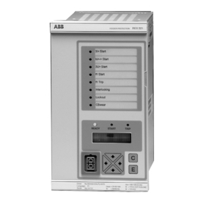
DEEsys DGF-M10 User manual

134 DEESYS TOTAL PRODUCTS GUIDE
MULTI FUNCTION GROUND FAULT
RELAY [GFR]-5C, 10C
Features
Rating & Specification
1. Multi-ground fault relay(GFR) is multi-functional and is able to detect multiple ground faults of monitoring circuit and is displayed
leakage in the circuit and fault current when earthing.
2. It is installed 8 bit MCU with A/D conventer and is configured to perform advanced functions for high relability.
3. It is a collective device that is intergrated many ground fault detector of conventional single unit.
4. It is capable to detect from minor grounding fault current(0.1A) to medium level fault current (10A)
5. It is configured to have operating time taps for adjustment of time setting is easy for protection coordination of distribution circuit
6. As wide display and indicators, it is able to enhance checking up and performance.
7. Watch dog function assures error - free operation.
8. The memory stores the last record of ground fault current of each circuit to facilitate following up in the event of accidents.
9. The ABS casing newly adopted offers improved durability and extended life of product.
10. All GFRs are tested EMC to ensures and high frequency & surge do not interfere design performance of GFR.
DGF - M10
DGF-M10(For 10 Circuits)
for protection against minor and major ground Leakage faults
AC 110/220V Operrable in Common or AC 240V
50/60㎐ Operable in common
9steps, of 0.1, 0.3, 0.5, 1, 2, 3, 5, 10 and Lock T:70% to 100% of current setting
9steps, of 0.05, 0.1, 0.3, 0.5, 1, 2, 3, 5, 10sec T:±10% for 0.05 T=0.1±25㎳
10Circuits
LED (Red) and Digtal Display one for each Circuit
Auto/Manual
-10℃~+50℃
Energized:Full vibration width 4㎜, 1000rpm, 10min
Deenergized:Full vibration width 4㎜, 1000rpm, 10min
Impact strength of 300㎨ applied to 3 axial directions of right & left. up & down, and behind & forward
Opn Cirr-Casing : AC 2000V
Opn Cir-OOpn Cir : AC 2000V
Test Cir-Terminals : AC 1000V
60㎐, 1min
Opn cir-Casing 10㏁ or more
Pon cir-Opn Cir : 10㏁ or more
Test Cir-Terminals : 10㏁ or more
7VA
AC 125V 5A/DC 30V 5A
2.0㎏
ZCT Rating 200㎃/100㎷ (ZR, ZS, ZB type)
Items
Usage
Control Power Voltage
Frequency
Operating current setting
Operating Time setting
Ground Fault Detection Circuit
Operating status Indicator
Resetting
Ambient Temperature
Vibration Resistance
Impact Resistance
Common frequency dielecric
resistance
Insulating Resistance
Power Consumption
Contact Capacity
Weight
ZCT(input)
DGF-M05(For 5 Circuits)
5Circuits
by DC 500V megger
5VA
1.7㎏

DEESYS TOTAL PRODUCTS GUIDE 135
GFR
Front plate
1. Line check button
2. Monitored circuit indicator(Digital)
3. Earth leakage level indicator
4. Hold check
5. Auto/check
6. Ground fault indicator for each circuit
7. Ground fault sensing current setting switch
8. Operating time setting switch
9. Self-test button for each circuit
10. Sensing current and operating time
11. Reset button
12. Power lamp
13. Sensing current setting check button
14. Operating time setting check button
DGF-M05T
Combination
1a
ARB(Contact)AC 250V/10A
Trip(MCCB) or Alarm
DGF-M05
None(Direct)
1a & (5C or 10C)
AC 250V/10A
Trip(MCCB) & Alarm
Model
DRB-005. 010
Contact
Contact Capacity
Purpose
DGF-M10T DGF-M10

136 DEESYS TOTAL PRODUCTS GUIDE
1. Line Check Button
When the switen is pressed, one by one time monitored
circuit number is changed to next circuit number and
ground fault current level of the circuit is displayed.
2. Monitored Circuit Indicator(Digital)
It indicates monitored circuit number in numberals.
3. Earth Leakage Level Indicator
The level of earth leakage or fault current is displayed.
4. Hold Check Switch(Stored memory of fault current level)
Pressing hold check switch, earth leakage level indicator is
displayed fault current of each circuit.
5. Auto./Manual Switch
If the switch is set to auto position, warning lamp(Red LED)
turns on to warn the status of the switch setting.
6. Ground Fault Indicator Lamp
The lamp of leaking circuit turns on when self-test button
of the same leaking circuit is pressed.
7. Ground Fault Sensing Current Setting Switch
Select suitable step of sensing current between 0.1 and 10A
rating as being reqired by characteristics of a line.
※Note : The relay does not operate in case of lock position
8. Operating Time Setting Switch
The switch is used to set required interval of operating time
from 0.05 to 10 seconds.
9. Self-Test Button
If the button of a circuit is pressed, the status of circuit is
simulated to real ground fault and ground fault indicator
lamp turns on to alarm fault status.
10. Sensing Current and Operating Time Reference Table
It is a table of current and time values that can be quoted
for current and time setting as the reference.
11. Reset Button
The button, if pressed, is intialized entire relay function.
12. Power Lamp(Green LED)
It turns on when the power of AC110/220V(or AC 240V)is
regularly supplied.
13. Sensing Current Setting Check Button
The button is used to display ground fault sensing current
setting for checking purpose.
14. Operating Time Setting Check Button
The button is used to display operating time setting of circuit
for checking purpose.
Outline Information
Performance Features
1. Multi-ground fault relay monitors a number of circuits
collectively and carries built-in functional arrangement for
ground leakage level indication and fault current level
indication.
2. It performs monitoring of all circuits consequently by the
command of MCU.
3. In case a ground fault current developed, it induces a
voltage in ZCT which is fed to ground fault current detection
circuit as an input.
4. After Input signal(voltage) is amplified, and then it is
supplied to CPU for processing.
5. CPU converts input by A/D converter for comparison to set
value of sensing current. And, if it is found more exceeding
the setting value, it is performed as followings.
1) Turns on ground fault indicator lamp upon the elapse of
setting interval of operating time.
2) Activates GFR or the circuit.
3) Indicates level of ground fault current on ground fault
current indicator in numeral value.
※Note : If Auto/Manual switch is set to Auto position the
warning lamp(Red LED) turns on, and the fault is repaired, all
operating indication of the circuit will disappear automatically.
MULTI FUNCTION GROUND FAULT
RELAY [GFR]-5C, 10C
6. Identification of indications : When leakages occur in plural
number of circuits on sometime, ground fault indicator lamps
for applicable circuits will light up at once. But ground fault
circuit number indicator and ground fault current level
indicator will display the value of first circuit detected. The
values of other fault circuits can be checked by pressing
circuit test button of respective circuit. If it is the auto reset
mode, fault current has been cleared. Such fault current can
be read out from the memory by pressing hold check button.
7. Reset If Auto/Manual switch is set to manual position after
the ground fault is repaired, press reset button to initialize the
performance or else fault indication will be kept on.

DEESYS TOTAL PRODUCTS GUIDE 137
Checking Items for Installation
1. Fabricate relay mounting panel of a suitable size and fix it
on which GFR be installed. Then install ZCT on the circuits
being monitored.
① Install ZCT of adequatable for the load (For selection of
ZCT specification and current rating. use ZCT
manufactured by us for ELD.)
② Ensuring GFR is in stalled at 10cm or more distance
where there are large current bus and strong magnet
field.
③ Install GFR on load circuit of single phase and three
phase power without exception.
④ check confinuity between GFR and ZCT by pressing
self-test button of each circuit line. The receiver is in
nomal status if ground fault current level indicator shows
a value in numerals Below of 18 if the connection of GFR
and ZCT is correctly made, and a value of 18 if they are
disconnected.
2. Connections to terminals on the back of GFR.(Refer to
external wiring diagram)
① One of two ZCT terminals(no ploarities) Shal be
connected to relay terminal of each circuit ①, ②, ③, ④,
⑤, ⑥, ⑦, ⑧, ⑨ and ⑩ and the other terminal to common
terminal ⓩ of GFR.
Checking Items Before Installation
Check up following points befor installation in order to ensure
satisfactory performance of GFR.
1. Connect AC220V power lines to terminals Po and P1 of GFR.
※Note : Operating power is set to AC 220V at factory when
delivered.
If AC 110V is used, slide the power voltage selector switch to
AC 110V position.
2. When the power os connected, power lamp(Green LED)
turns on to indicate power suppy.
3. Check up digital displays by pressing circuit test switch.
The circuit number on display changes by advancing one
circuit at each of pressing the button and ground fault
current level indicator will remain displaying all the
while of testing.
After an elapse of about 25 seconds or so without pressing
test button further, the indication will disappear automatically.
4. Check up operating time settings of each circuit by pressing
operating time check switch.
5. Check up fault sensing current setting by pressing ground
fault sensing setting switch.
6. Check up internal circuits by pressing self- test button of
each circuit.
If the button is pressed of a circuit, relay of the circuit and
ground fault indicator lamp(RED LED) and circuit indicator
relay activate to show status of circuits.(The value of digital
display represent assumed state of grounding fault).
7. Carry out the test of item 6 after auto/manual switch is set
mannual position.
8. Return to the initial status by pressing the reset switch after
finishing the above test.
② With GFR, terminals ⓐ through ⓙ are ‘a’ contacts for
external relays, and terminal COM is ‘contact’ for
external
relays.
The terminals could be used for control of circuit
breakers, external alarm buzzer, and leakage fault in
dication on central control board.
③ Terminals Ta and Tc are provided to use the contacts for
external indicators(buzzer, lamp).
④ Terminal (E) is for grounding which is connedted to the
ground terminal of distribution board. (Refer to external
wiring diagram for connections).
⑤ The control power of relay should be connected an
independent sonrce which is not distributed from main
source.
999

138 DEESYS TOTAL PRODUCTS GUIDE
External contacts wiring diagram(Trip contacts)
Internal block diagram
External terminal arrangement
MULTI FUNCTION GROUND FAULT
RELAY [GFR]-5C, 10C

DEESYS TOTAL PRODUCTS GUIDE 139
Combination DGF-M05T
Combination DGF-M10T
Aux relay board is a power relay which controls output power according to the
input signals of industrial uses, and consists of set type relays controlling MCCB
or MC coils.
● Ensure to use Aux Relays (DRB-010. 005) when DGF-M10, M05 are used
to drive MCCB and trip rather than the using them as central control board
lamp indication.
● It is insulated completely between and among input, output, and power
lines.
● Single board is capable to control 5or 10 circuits
● Formerly exposed aux relays are now internally located in order to prevent
mal-functioning caused by moisture hazardous to insulation.
Features
GFR output
Inetrnal block diagram
Terminal arrangement
Rated Specification
External wiring diagram
External dimension
MODEL
Rated Voltage
Rated Frequency
Relay Contact Rating
DRB-010(10C), DRB-005(5C)
AC 110V/220V
50/60㎐
AC 250V, 10A
AUX RELAY BOARD[ISOLATION]-5C, 10C
This manual suits for next models
3
Table of contents
Other DEEsys Relay manuals
