manuals.online logo
Brands
  1. Home
  2. •
  3. Brands
  4. •
  5. Siemens
  6. •
  7. Relay
  8. •
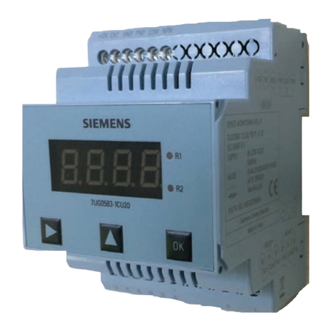
  9. Siemens 7UG0 Series User manual

Siemens 7UG0 Series User manual

This manual suits for next models

1

Other Siemens Relay manuals

Siemens 61H Manual

Siemens

Siemens 61H Manual

Siemens 7UG0 480-1IU20 User manual

Siemens

Siemens 7UG0 480-1IU20 User manual

Siemens 7 SK 88 A Series User manual

Siemens

Siemens 7 SK 88 A Series User manual

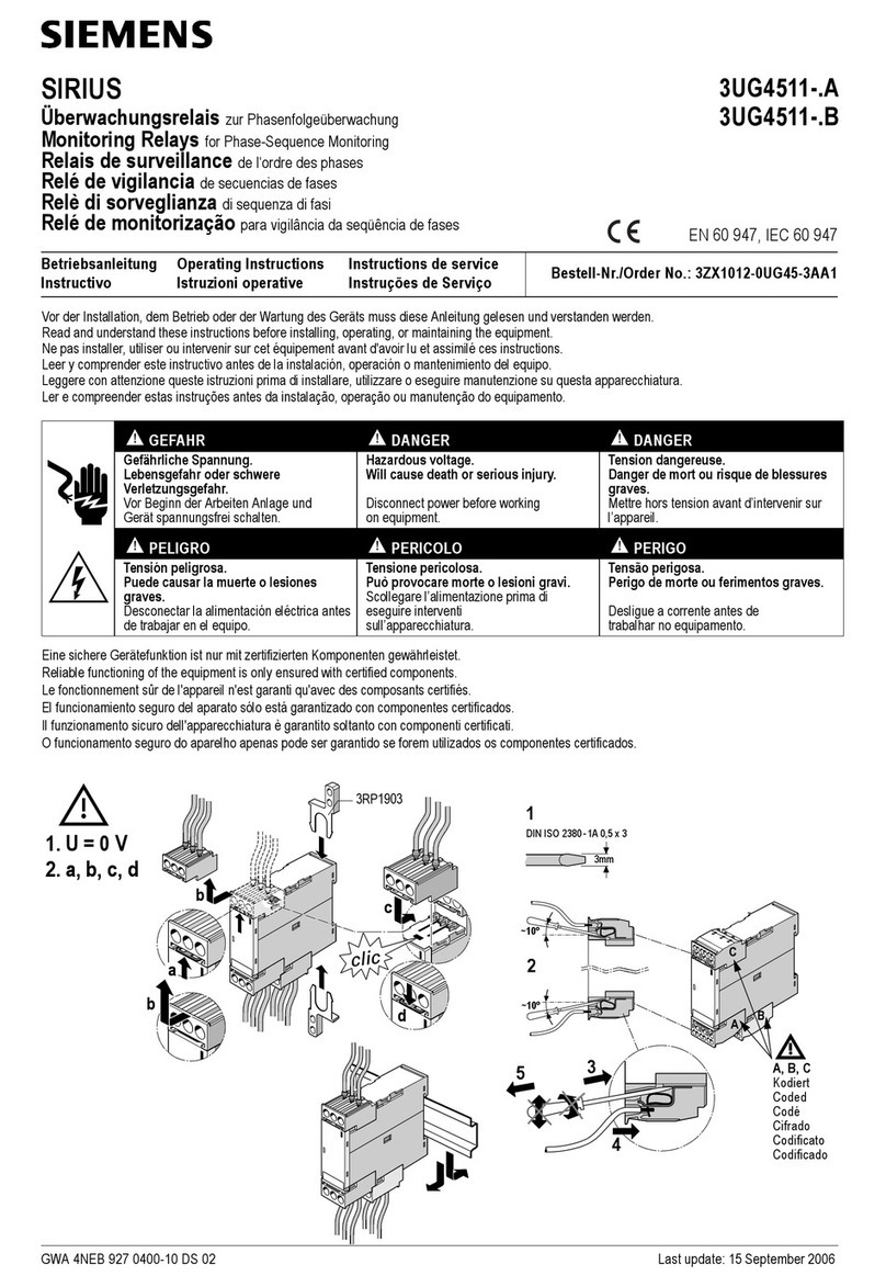
Siemens SIRIUS 3UG4513 User manual

Siemens

Siemens SIRIUS 3UG4513 User manual

Siemens 3RS2 User manual

Siemens

Siemens 3RS2 User manual

Siemens SIPROTEC 7UM62 User manual

Siemens

Siemens SIPROTEC 7UM62 User manual

Siemens Sirius 3UG4614 User manual

Siemens

Siemens Sirius 3UG4614 User manual

Siemens 3RB23 User manual

Siemens

Siemens 3RB23 User manual

Siemens SIRIUS 3RU5 36 B Series User manual

Siemens

Siemens SIRIUS 3RU5 36 B Series User manual

Siemens SIRIUS 3UG4624 User manual

Siemens

Siemens SIRIUS 3UG4624 User manual

Siemens SIRIUS 3RF23 0 Series User manual

Siemens

Siemens SIRIUS 3RF23 0 Series User manual

Siemens SIRIUS 3TK2825 User manual

Siemens

Siemens SIRIUS 3TK2825 User manual

Siemens SIPROTEC 7SA511 User manual

Siemens

Siemens SIPROTEC 7SA511 User manual

Siemens 3TK2856 User manual

Siemens

Siemens 3TK2856 User manual

Siemens 3RB2483-4AA1 User manual

Siemens

Siemens 3RB2483-4AA1 User manual

Siemens 3RS1800 User manual

Siemens

Siemens 3RS1800 User manual

Siemens 3UA60 User manual

Siemens

Siemens 3UA60 User manual

Siemens RL Manual

Siemens

Siemens RL Manual

Siemens SIRIUS 3TK2820 User manual

Siemens

Siemens SIRIUS 3TK2820 User manual

Siemens SIRIUS 3RQ3118-1 Series User manual

Siemens

Siemens SIRIUS 3RQ3118-1 Series User manual

Siemens SIPROTEC4 7SJ61 User manual

Siemens

Siemens SIPROTEC4 7SJ61 User manual

Siemens SIVACON 8PS User manual

Siemens

Siemens SIVACON 8PS User manual

Siemens 7SR17 Rho User manual

Siemens

Siemens 7SR17 Rho User manual

Siemens 3UA50 User manual

Siemens

Siemens 3UA50 User manual

Popular Relay manuals by other brands

Woodward BU1-DC2 manual

Woodward

Woodward BU1-DC2 manual

ABB SSR32 product manual

ABB

ABB SSR32 product manual

Shelly Pro Series user manual

Shelly

Shelly Pro Series user manual

GE MVAX 11 Technical manual

GE

GE MVAX 11 Technical manual

ABB RELION REF615R manual

ABB

ABB RELION REF615R manual

Kemo Electronic B197 quick guide

Kemo Electronic

Kemo Electronic B197 quick guide

Seg MRM3 manual

Seg

Seg MRM3 manual

Basler BE1-700C manual

Basler

Basler BE1-700C manual

CD Automation REVEX 2PH 280A user manual

CD Automation

CD Automation REVEX 2PH 280A user manual

ABB SPAJ 142 C User manual and technical description

ABB

ABB SPAJ 142 C User manual and technical description

Ruelco 1S04 Operation manual

Ruelco

Ruelco 1S04 Operation manual

Basler V3E Z1P B2C1F instruction manual

Basler

Basler V3E Z1P B2C1F instruction manual

GE DGP instruction manual

GE

GE DGP instruction manual

Kyongbo Electronics GDR-D01 user manual

Kyongbo Electronics

Kyongbo Electronics GDR-D01 user manual

Eaton easyE4 series Application note

Eaton

Eaton easyE4 series Application note

Leuze MSI-SR5B Original operating instructions

Leuze

Leuze MSI-SR5B Original operating instructions

Littelfuse SE-330AU manual

Littelfuse

Littelfuse SE-330AU manual

EVA Logik ZW12 user manual

EVA Logik

EVA Logik ZW12 user manual

manuals.online logo
manuals.online logoBrands
  • About & Mission
  • Contact us
  • Privacy Policy
  • Terms and Conditions

Copyright 2025 Manuals.Online. All Rights Reserved.

1
s
Operating Instructions
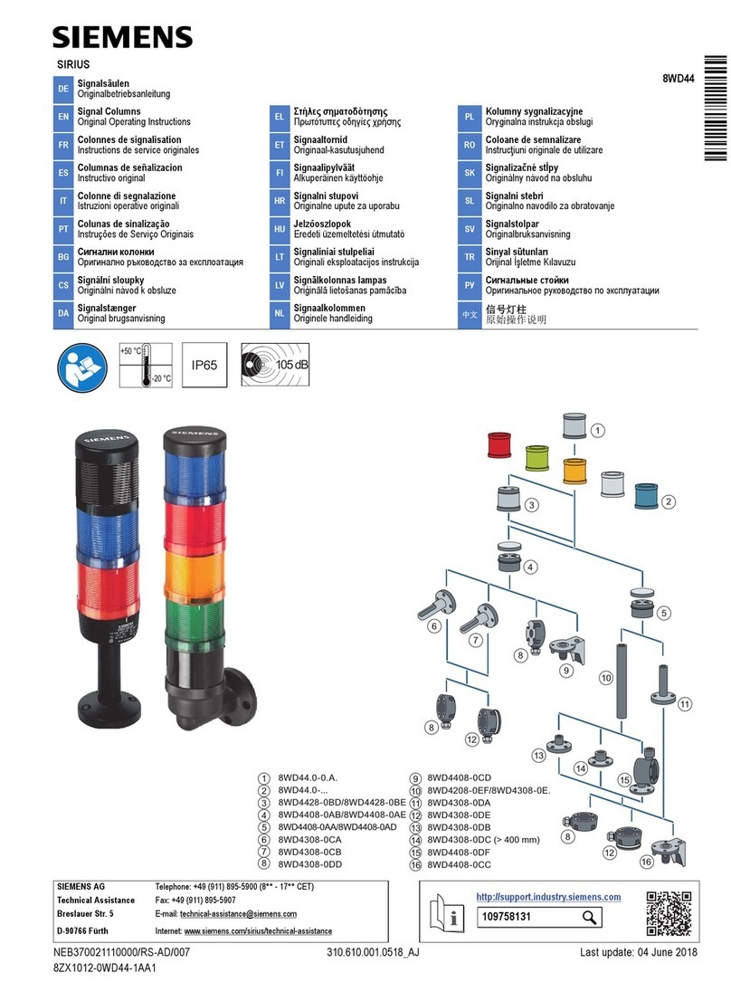
Thermistor Motor Protection Relay
7UG0881-1BU20
7UG0
IEC 60947-5-1
IEC 60947-8 A
Please read and understand these instructions before installing,
operating, or maintaining the equipment.
DANGER
Hazardous voltage can cause death or serious injury.
Disconnect power before working on equipment.
CAUTION
Reliable functioning of the equipment is only ensured
with certied components.
Overvoltage category II
(Refer IEC 60947-1)
NOTICE
This product has been designed for environment A. Use of this product
in environment B may cause unwanted electromagnetic disturbances in
which case the user may require to take adequate mitigation measures.
Technical Data
Designation 7UG0881-1BU20
Type Thermistor Motor Protection Relay
Control Supply (Uc) 110 - 240V AC/DC
Tolerance on Control supply 0.85x Uc… 1.1x Uc
Frequency 50/60Hz
Operating temperature 0 to 50°C , 95%RH (non-condensing)
Sensor operating mode
(all values in ohms)
Sensor Short : ≤ 40
Sensor Healthy : ≥ 44 (±3) to < 3.8K (±150)
Sensor Trip : ≥ 3.8K (±150) to < 5.5K (±150)
Sensor Open : ≥ 5.5K (±150) & Above
Sensor Recovery/ Cut-in / Reset : ≤ 1.5K (±60)
Trip Time Instantaneous
Initialization time 3 sec
Relay modes Failsafe and Non-Failsafe mode (Selectable)
Device Operating mode Auto / Manual (Selectable)
Rated output relay current 5A (AC12)
Power consumption (@ 230V) 3 VA
Terminal connections
Thermistor motor protection relay is used to monitor the winding temperature of motors / generators using PTC sensors and to protect them from
abnormal overheating in accordance to the product standard IEC 60947-8, control units for built-in thermal protection (PTC) for rotating electrical
machines.
PTC resistor sensors which are built-in into the motor windings, measures the motor heating. With increase of the temperature in the motor, the
resistance of the PTC sensors will increase.
Operating modes :
1. Sensor Short : Sensor is short / damaged.
2. Sensor Healthy : The motor is running safely.
3. Sensor Trip : When the motor exceeds its temperature beyond its safety limit, it is in trip condition. It stays in trip condition until the motor cools
down and reaches Cut-in.
4. Sensor Open : Sensor is open / break.
5. Sensor Recovery / Cut-in / Reset : After the motor cools down, it reaches Cut-in condition. The relay switches automatically, in Auto mode.
Whereas in Manual mode, the user has to manually reset (PRG Key or Remote reset R1-S1) when in Cut-in condition.
7UG0881 - 1BU20
0.5 Nm
5
Solid
1 x (0.75 to 2.5) mm2
2 x 0.5 to 2 x 1.5 mm2
5
Stranded with end sleeve
1 x (0.5 to 2.5) mm2
2 x (0.5 to 1.5) mm2
Note: 1. Compatible with both single and triple PTCs.
2. At ambient, when PTC sensors connected in series, total resistance value
should not exceed more than 1.5kΩ i.e. (R1+R2+R3+...+Rn)Amb ≤ 1.5kΩ.
2
Front panel description
SIEMENS
S
"ON" (Green)
& R
Relayindication (Red)
Sensor Condition (Yellow)
S
S& R LED's. The changes are auto-saved and retained.
3
Timing Diagrams and LED indications
After cut-in, the reIay switches its state
automaticaIIy to HeaIthy condition
With sensor in cut-in mode, R LED will be
slow blinking. Press the "PRG" key to reset
the relay and bring the operating mode to
"Sensor Healthy condition"
R-LED
(Failsafe) R-LED
(Non-Failsafe) S-LED
R-LED
(Failsafe) R-LED
(Non-Failsafe) S-LED
44
40
44
40
Dimensional drawings
Siemens Ltd. Product development is a continuous process. Consequently
the data indicated in this Leaet is subject to change without
prior notice. For latest issue contact our sales ofces.
SACHIN ENTERPRISE
Disposal
Siemens product are environment friendly, which predominantly
consist of recyclable materials.
For disposals we recommend disassembling and separation into
following materials:
METALS: Segregate into Ferrous & Non Ferrous types for recycling
through authorised dealer.
PLASTICS: Segregate as per material type for recycling through
authorised dealer. Because of the long lifetime of Siemens
products the disposal guidelines may be replaced by other national
regulations when taking the product out of service.
The local customer care service is available at any time to answer
disposal-related questions
Customer Care Toll free no. 1800 209 0987 Email: [email protected] Order No. A5E43375428A/AB
35
mm
60mm