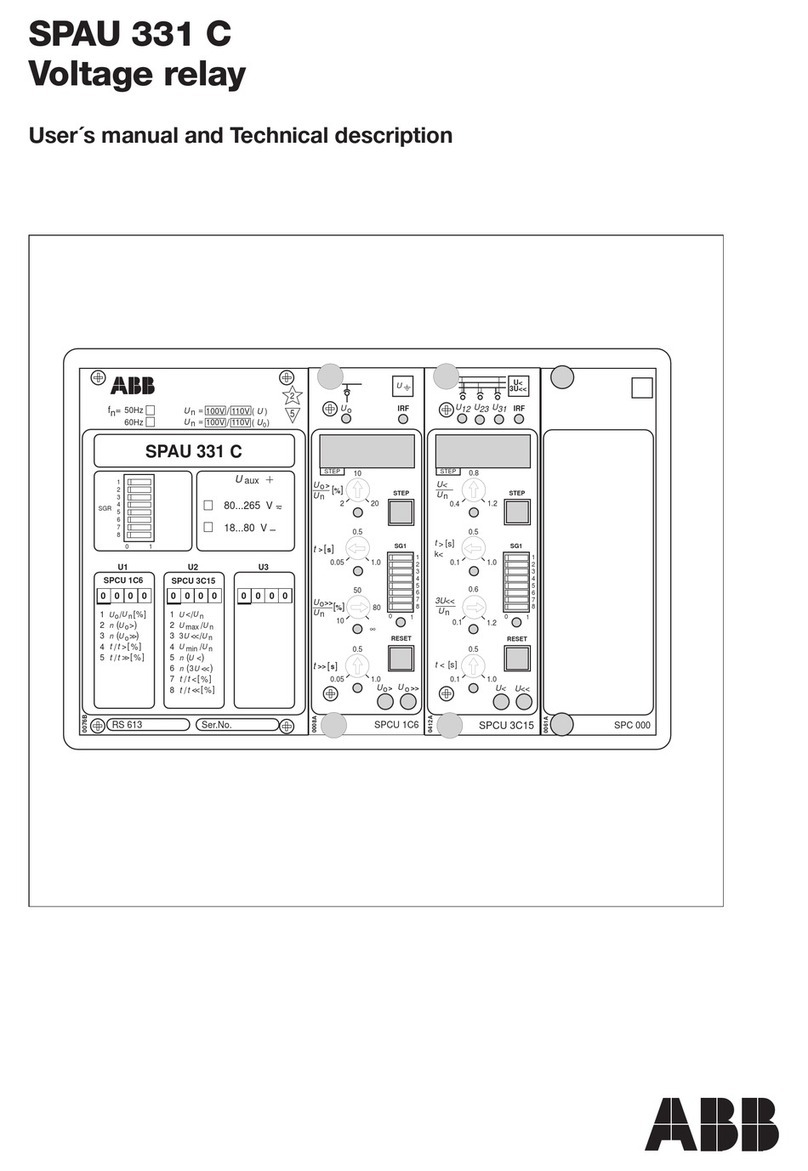
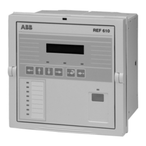
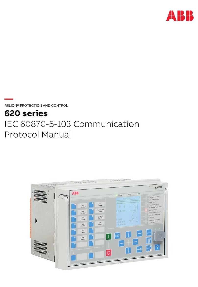
ABB REM 610 Product manual

REM 610
Motor Protection Relay
Technical Reference Manual - ANSI Version


3
REM 610
1MRS 755537
Issued: March 31, 2005
Version: A
We reserve the right to change data without prior notice.
Motor Protection Relay
Technical Reference Manual - ANSI Version
Contents
1. Introduction ...............................................................................6
1.1. About this manual .........................................................................6
1.2. The use of the relay ......................................................................6
1.3. Features ........................................................................................6
1.4. Guarantee .....................................................................................8
1.5. Revision history .............................................................................8
2. Safety information..................................................................... 9
3. Instructions ..............................................................................10
3.1. Application ...................................................................................10
3.2. Requirements ..............................................................................10
3.3. Configuration ...............................................................................10
4. Technical description .............................................................14
4.1. Functional description .................................................................14
4.1.1. Product functions .............................................................14
4.1.1.1. Schema of product functions ..............................14
4.1.1.2. Protection functions ............................................14
4.1.1.3. Inputs .................................................................15
4.1.1.4. Outputs ...............................................................15
4.1.1.5. Emergency start .................................................15
4.1.1.6. Restart disable ...................................................15
4.1.1.7. Motor start up .....................................................16
4.1.1.8. Rated current of the protected unit .....................16
4.1.1.9. Disturbance recorder ..........................................17
4.1.1.10.HMI ....................................................................17
4.1.1.11.Non-volatile memory ..........................................17
4.1.1.12.Self-supervision .................................................17
4.1.2. Measurements .................................................................19
4.1.3. Configuration ....................................................................20
4.1.4. Protection .........................................................................22
4.1.4.1. Block diagram ....................................................22
4.1.4.2. Thermal overload protection ..............................22
4.1.4.3. Start-up supervision ...........................................29
4.1.4.4. Short-circuit protection .......................................30
4.1.4.5. Undercurrent protection .....................................31
4.1.4.6. Ground-fault protection ......................................31
4.1.4.7. Unbalance protection .........................................32

4
1MRS 755537
Motor Protection Relay
Technical Reference Manual
REM 610
4.1.4.8. Phase reversal protection .................................. 33
4.1.4.9. Cumulative start-up time counter .......................34
4.1.4.10.Circuit-breaker failure protection ........................ 34
4.1.4.11.Temperature protection (optional) .....................35
4.1.4.12.Temperature protection using thermistors .........36
4.1.4.13.Settings .............................................................. 40
4.1.4.14.Technical data on protection functions ...........51
4.1.5. Trip-circuit supervision ..................................................... 54
4.1.6. Target LEDs and operation target messages ..................56
4.1.7. Motor running time counter ..............................................56
4.1.8. Monitoring of demand values ..........................................57
4.1.9. Commissioning tests ........................................................57
4.1.10.Disturbance recorder .......................................................57
4.1.10.1.Function ............................................................. 57
4.1.10.2.Disturbance recorder data ................................. 58
4.1.10.3.Control and target of disturbance
recorder status ................................................... 59
4.1.10.4.Triggering ..........................................................59
4.1.10.5.Settings and unloading ......................................59
4.1.10.6.Event code of the disturbance recorder .............59
4.1.11.Recorded data of the last events ..................................... 60
4.1.12.Communication ports ....................................................... 62
4.1.13.IEC 60870-5-103 remote communication protocol ..........63
4.1.14.Modbus remote communication protocol ......................... 66
4.1.14.1.Protocol overview .............................................. 66
4.1.14.2.Profile of Modbus REM 610............................... 67
4.1.14.3.SPA bus communication protocol parameters ...79
4.1.14.4.Event codes .......................................................93
4.1.15.Self-supervision (IRF) system ..........................................97
4.1.15.1.Self-supervision of the RTD module .................. 98
4.1.16.Relay parameterization ....................................................99
4.2. Design description ......................................................................99
4.2.1. Input/output connections .................................................99
4.2.2. Serial communication connections ................................ 104
4.2.3. Technical data ............................................................... 108
5. Setting calculations and application examples ................. 113
5.1. Setting calculations ...................................................................113
5.1.1. FLA secondary scaling factor ........................................113
5.1.2. Thermal overload protection ..........................................113
5.1.2.1. Selecting weighting factor p ............................. 114
5.1.2.2. Safe stall time for hot starts ............................. 116

1MRS 755537 Motor protection Relay
Technical Reference Manual
REM 610
5
5.1.2.3. Checking the set safe stall time for cold starts .119
5.1.2.4. Checking the set safe stall time for a
single start ........................................................120
5.1.2.5. Restart disable level, 49 RESTDIS ..................120
5.1.2.6. Prior alarm level, 49 ALARM ............................120
5.1.2.7. Time constant multiplier, Kc ................................. 120
5.1.3. Start-up supervision .......................................................120
5.1.3.1. Start-up supervision based on thermal stress
calculation ........................................................120
5.1.3.2. Checking the need for speed switch ................121
5.1.4. Cumulative start-up time counter ...................................121
5.1.5. Short-circuit protection ...................................................122
5.1.6. Unbalance and phase reversal protection .....................122
5.1.6.1. Selecting the pickup value for element 46 .......122
5.1.6.2. Selecting the time constant, 46 TDIAL .............122
5.1.6.3. Connection with two phase
current transformers .........................................123
5.1.7. Ground-fault protection ...................................................123
5.1.7.1. Stabilizing virtual ground-fault currents ............124
5.1.7.2. Increasing the sensitivity of the ground-fault
protection .........................................................124
5.1.8. Circuit-breaker failure protection ....................................124
5.1.9. Temperature protection (optional) ..................................124
5.2. Application examples ................................................................125
5.2.1. Protecting a circuit-breaker controlled motor .................125
5.2.2. Protecting a motor at an ambient temperature other than
40°C ...............................................................................126
5.2.3. Protecting a contactor controlled motor .........................127
5.2.4. Protecting non-rotating objects ......................................128
5.2.5. Ground-fault protection in an isolated or a compensated
network ..........................................................................128
5.2.6. Ground-fault protection in a solidly grounded network ...128
6. Ordering information ............................................................130
7. Revision history of REM 610 ................................................132
7.1. Revision identification ...............................................................132
7.2. Changes and additions to the earlier released revision A .........132
8. References .............................................................................133
9. Abbreviations ........................................................................134
10.Check lists ..........................................................................136

6
1MRS 755537
Motor Protection Relay
Technical Reference Manual
REM 610
1. Introduction
1.1. About this manual
This manual provides thorough information on the protection relay REM 610
Revision B and its applications, focusing on giving a technical description of the
relay. For more information about earlier revisions, refer to section Revision history.
Refer to the Operator’s Manual for instructions on how to use the
Human-Machine Interface (HMI) of the relay, also known as the Man-Machine
Interface (MMI), and to the Installation Manual for installation of the relay.
1.2. The use of the relay
REM 610 is a versatile multifunction protection relay mainly designed to protect
motors in a wide range of motor applications.
REM 610 is based on a microprocessor environment. A self-supervision system
continuously monitors the operation of the relay.
The HMI includes a Liquid Crystal Display (LCD) which makes the local use of the
relay safe and easy.
Local control of the relay via serial communication can be carried out with a
computer connected to the front communication port. Remote control can be carried
out via the rear connector connected to the control and monitoring system through
the serial communication bus.
1.3. Features
• Three-phase thermal overload protection
• Three-phase motor start-up supervision based on thermal stress calculation with
speed switch blocking ability
• Three-phase overcurrent protection with definite-time characteristic and speed
switch blocking ability
• Three-phase short-circuit protection with instantaneous or definite-time
characteristic
• Three-phase undercurrent (loss of load) protection with definite-time
characteristic
• Non-directional ground-fault protection with definite-time characteristic
• Three-phase unbalance protection based on the negative-phase-sequence current
with inverse definite minimum time characteristic
• Phase reversal protection based on the negative-phase-sequence current
• Cumulative start-up time counter with restart disable function
• Circuit-breaker failure protection
• Temperature protection elements with definite-time characteristic
• Emergency start function
• Optional RTD module
• with six measuring inputs
• supports PTC thermistors and various RTD sensors

1MRS 755537 Motor protection Relay
Technical Reference Manual
REM 610
7
• three additional galvanically isolated digital inputs
• Disturbance recorder
• recording time up to 80 seconds
• triggering by one or several internal or digital input signals
• records four analogue channels and up to eight user-selectable digital channels
• adjustable sampling rate
• Non-volatile memory for
• up to 100 event codes with time stamp
• setting values
• disturbance recorder data
• recorded data of the five last events with time stamp
• number of pickups for protection elements
• operation target messages and LEDs showing the status at the moment of
power failure
• Battery back-up for real-time clock
• Battery charge supervision
• Four accurate current inputs
• Two galvanically isolated digital inputs and three additional digital inputs on the
optional RTD module
• Time synchronization via a digital input
• All settings can be modified with a PC
• HMI with an alphanumeric LCD and manoeuvring buttons
• eight programmable LEDs
• Detachable plug-in unit
• Three normally open power output contacts
• Trip-circuit supervision
• Two change-over signal output contacts
• Output contact functions freely configurable for desired operation
• Optical front communication connection: wirelessly or via cable
• Optional rear communication module with plastic fibre-optic, combined fibre-
optic (plastic and glass) or RS-485 connection for system communication using
the SPA-bus, IEC 60870-5-103 or Modbus (RTU and ASCII) communication
protocol
• Continuous self-supervision of electronics and software. At an internal relay
fault, all protection elements and outputs will be blocked.
• User-selectable rated frequency 50/60 Hz
• User-selectable password protection for the HMI
• Display of primary current values
• Demand values
• Multi-language support

8
1MRS 755537
Motor Protection Relay
Technical Reference Manual
REM 610
1.4. Guarantee
Please inquire about the terms of guarantee of your nearest ABB representative.
1.5. Revision history
Version Date Remarks
AApril 11, 2005 Modified for ANSI compliance from the original manual
version 1MRS752263-MUM version B

1MRS 755537 Motor protection Relay
Technical Reference Manual
REM 610
9
2. Safety information
Dangerous voltages can occur on the connectors, even though the
auxiliary voltage has been disconnected.
National and local electrical safety regulations must always be
followed.
The device contains components which are sensitive to electrostatic
discharge. Unnecessary touching of electronic components must
therefore be avoided.
The frame of the device has to be carefully grounded.
Only a competent electrician is allowed to carry out the electrical
installation.
Non-observance can result in death, personal injury or substantial
property damage.
Breaking the sealing tape on the upper handle of the device will result
in loss of warranty and proper operation will no longer be guaranteed.
When the plug-in unit has been detached from the case, do not touch
the inside of the case. The relay case internals may contain high voltage
potential and touching these may cause personal injury.
!

10
1MRS 755537
Motor Protection Relay
Technical Reference Manual
REM 610
3. Instructions
3.1. Application
REM 610 is a versatile multifunction protection relay mainly designed for protection
of standard medium and large MV asynchronous motors in a wide range of motor
applications. It handles fault conditions during motor start up, normal run, idling,
and cooling down at standstill, e.g. in pump, fan, mill or crusher applications.
The large number of integrated protection functions makes REM 610 a complete
protection against motor damage. The relay can be used with both circuit-breaker
controlled and contactor controlled drives.
REM 610 can equally well be used to protect, for instance, feeder cables and power
transformers which require thermal overload protection and, for instance, single-,
two- or three-phase overcurrent or non-directional ground-fault protection.
3.2. Requirements
To secure correct and safe operation of the relay, preventive maintenance is
recommended to be performed every five years when REM 610 is operating under
the specified conditions; see below and section Technical data.
When being used for real-time clock or recorded data functions, the battery should
be changed every five years.
Environmental conditions
3.3. Configuration
Setting and connection examples
The appropriate configuration of the output contact matrix enables the use of the
signals from the protection elements as contact functions. The pickup signals can be
used for blocking co-operating protection relays and signalling.
Figures Fig. 3.3.-1 and Fig. 3.3.-2 represent REM 610 with the default
configuration: all trip signals are routed to trip the circuit breaker. In Fig. 3.3.-1 the
residual current is measured via a core-balance current transformer and in
Fig. 3.3.-2 via a summation connection of the phase current transformers.
Fig. 3.3.-3 represents REM610 connected to a contactor controlled motor with the
trips routed to trip the contactor.
• Recommended temperature range (continuous) -10...+55°C
• Limit temperature range (short-term) -40...+70°C
• Temperature influence on the operation accuracy of the
protection relay within the specified service temperature range
0.1%/°C
• Transport and storage temperature range -40...+85°C

1MRS 755537 Motor protection Relay
Technical Reference Manual
REM 610
11
Fig. 3.3.-1 Connection diagram, example 1
RESTART DISABLE
49
IRF
Warning
Self-supervision
*Restart disable
ALARM
50P
Blocking
37
Blocking
51N
Blocking
46
Blocking
66
46R
Motor start up
49/38 -1
49/38 -2
Restart disable
*Restart disable signal from 49
** Restart disable signal from 66
TRIP
External restart disable
External trip
External triggering of CBFAIL
Indications cleared
Output contacts unlatched
Memorized values cleared
Setting group selection
Time Sync
SGF1...SGF5
SGL1...SGL8
**Restart disable
MOTOR ST
ALARM
ALARM
EXT TRIP
M
3 ~
X2. 1 7 8 1 2 3 4 5 6 1 2
~
Optional
X3. 1
7
8
9
10
11
12
13
14
15
16
17
18
19
20
21
22
23
24
RTD/PTC1
RTD2
RTD3
RTD4/PTC2
RTD5
RTD6
+
-DIFF
+
-DIFF
+
-DIFF
+
-DIFF
+
-DIFF
+
-DIFF
COMMON
COMMON
COMMON
COMMON
COMMON
COMMON
= Factory Defaul t
ConnDiagr2REM610_f.eps
D15
6 5
D12
21 22
IR F
3 4 5
PO3
12 13
PO1
16 17 18
D14
4 3
D13
2 1
D11
23 24
SO2
6 7 8
SO1
9 10 11
PO2
14 15 19X3.1 X4. 1
Optional
SGF1/ 7
SGB5 SGB4 SGB3 SGB2 SGB1 1 11 1 1
2 2 2 2 2
3 33 3 3
4 44 4 4
5 55 5 5
6 6 6 6 6
7 77 7 7
8 88 8 8
9 99 9 9
10 10 10 10 10
11 11 11 11 11
12 12 12 12 12
13 13 13 13 13
14 14 14 14 14
16 16 16 16 16
17 17 17 17 17
18 18 18 18 18
19 19 19 19 19
15 15 15 15 15
SGR5 SGR4 SGR3 SGR2 SGR1
8 8 8 8 8
99
99 9
10 10 10 10 10
11 11 11 11 11
12 12 12 12 12
13 13 13 13 13
7 7 7 7 7
5 5 5 5 5
666 66
1 1 1 1 1
2 2 2 2 2
3 3 3 3 3
4 4 4 4 4
14 14 14 14 14
A
B
C
U
aux
+
+
+
-
-
1
0
CS
C
CS
T
Emergency Start
Emergency Start
Emergency Start
Emergency Start
Speed switch/blocking
(48/14 PICKUP)2(48/14 TDLY)
/(48/14) PICKUP
TRIP
TRIP
PICKUP
TRIP
PICKUP
TRIP
PICKUP
TRIP
PICKUP
TRIP
TRIP
TRIP
TRIP

12
1MRS 755537
Motor Protection Relay
Technical Reference Manual
REM 610
Fig. 3.3.-2 Connection diagram, example 2
RESTART DISABLE
49
IRF
Warning
Self-supervision
*Restart disable
ALARM
Speed switch/blocking
PICKUP
TRIP
TRIP
PICKUP
TRIP
PICKUP
TRIP
PICKUP
TRIP
PICKUP
TRIP
TRIP
TRIP
TRIP
50P
Blocking
37
Blocking
51N
Blocking
46
Blocking
66
46R
Motor start up
49/38 -1
49/38 -2
Restart disable
*Restart diable signal from 49
** Restart disable signal from 66
TRIP
External restart disable
External trip
External triggering of CBFAIL
Indications cleared
Output contacts unlatched
Memorized values cleared
Setting group selection
Time sync
SGF1...SGF5
SGL1...SGL8
**Restart disable
MOTOR ST
ALARM
ALARM
EXT TRIP
X2. 1 7 8 1 2 3 4 5 6 1 2
~
Optional
X3. 1
7
8
9
10
11
12
13
14
15
16
17
18
19
20
21
22
23
24
RTD/PTC1
RTD2
RTD3
RTD4/PTC2
RTD5
RTD6
+
-DIFF
+
-DIFF
+
-DIFF
+
-DIFF
+
-DIFF
+
-DIFF
COMMON
COMMON
COMMON
COMMON
COMMON
COMMON
= Factory Defaul t
ConnDiagr1REM610_e.eps
D15
6 5
D12
21 22
IR F
3 4 5
PO3
12 13
PO1
16 17 18
D14
4 3
D13
2 1
D11
23 24
SO2
6 7 8
SO1
9 10 11
PO2
14 15 19X3.1 X4. 1
Optional
SGF1/ 7
SGB5 SGB4 SGB3 SGB2 SGB1 1 11 1 1
2 2 2 2 2
3 33 3 3
4 44 4 4
5 55 5 5
6 6 6 6 6
7 77 7 7
8 88 8 8
9 99 9 9
10 10 10 10 10
11 11 11 11 11
12 12 12 12 12
13 13 13 13 13
14 14 14 14 14
16 16 16 16 16
17 17 17 17 17
18 18 18 18 18
19 19 19 19 19
15 15 15 15 15
SGR5 SGR4 SGR3 SGR2 SGR1
9 9 9 9 9
10 10 10 10 10
11 11 11 11 11
12 12 12 12 12
13 13 13 13 13
U
aux
+
+
+
-
-
1
0
CS
C
CS
T
A
B
C
555 5 5
666 6 6
777 7 7
1 1 1 1 1
2 2 2 2 2
3 3 3 3 3
4 4 4 4 4
14 14 14 14 14
(48/14 PICKUP)2(48/14 TDLY)
/(48/14)
Emergency Start
Emergency Start
Emergency Start
Emergency Start
888 88

1MRS 755537 Motor protection Relay
Technical Reference Manual
REM 610
13
Fig. 3.3.-3 Connection diagram, example 3
RESTART DISABLE
49
IRF
Warning
Self-supervision
*Restart disable
ALARM
50P
Blocking
37
Blocking
51N
Blocking
46
Blocking
66
46R
Motor start up
49/38 -1
49/38 -2
*Restart diable signal from 49
** Restart disable signal from 66
TRIP
External restart disable
External trip
External triggering of CBFAIL
Indications cleared
Output contacts unlatched
Memorized values cleared
Setting group selection
Time sync
SGF1...SGF5
SGL1...SGL8
PICKUP
PICKUP
PICKUP
PICKUP
**Restart disable
MOTOR ST
ALARM
ALARM
EXT TRIP
X2. 1 7 8 1 2 3 4 5 6 1 2
~
Optional
X3. 1
7
8
9
10
11
12
13
14
15
16
17
18
19
20
21
22
23
24
RTD/PTC1
RTD2
RTD3
RTD4/PTC2
RTD5
RTD6
+
-
DIFF
+
-
DIFF
+
-
DIFF
+
-
DIFF
+
-
DIFF
+
-
DIFF
COMMON
COMMON
COMMON
COMMON
COMMON
COMMON
= Factory Defaul t
ConnDiagr3REM610_d.eps
D15
6 5
D12
21 22
IR F
3 4 5
PO3
12 13
PO1
16 17 18
D14
4 3
D13
2 1
D11
23 24
SO2
6 7 8
SO1
9 10 11
PO2
14 15 19X3.1 X4. 1
Optional
SGF1/ 7
SGB5 SGB4 SGB3 SGB2 SGB1 1 1 1 1 1
2 2 2 2 2
3 3 3 3 3
4 4 4 4 4
5 5 5 5 5
6 6 6 6 6
7 7 7 7 7
8 8 8 8 8
9 9 9 9 9
10 10 10 10 10
11 11 11 11 11
12 12 12 12 12
13 13 13 13 13
14 14 14 14 14
16 16 16 16 16
17 17 17 17 17
18 18 18 18 18
19 19 19 19 19
15 15 15 15 15
SGR5 SGR4 SGR3 SGR2 SGR1
U
aux
+
+
CS
T
+
+
CS
C
-
A
B
C
1 1 1 1 1
2 2 2 2 2
3 3 3 3 3
4 4 4 4 4
Emergency Start
Emergency Start
Emergency Start
Emergency Start
Restart Disable
8 8 8 8 8
99
99 9
10 10 10 10 10
11 11 11 11 11
12 12 12 12 12
13 13 13 13 13
7 7 7 7 7
5 5 5 5 5
666 66
14 14 14 14 14
Speed switch/blocking
(48/14 PICKUP)2(48/14 TDLY)
/(48/14) PICKUP
TRIP
TRIP
TRIP
TRIP
TRIP
TRIP
TRIP
TRIP
TRIP

14
1MRS 755537
Motor Protection Relay
Technical Reference Manual
REM 610
4. Technical description
4.1. Functional description
4.1.1. Product functions
4.1.1.1. Schema of product functions
Fig. 4.1.1.1.-1 Product functions
4.1.1.2. Protection functions
Refer to sections:
•4.1.4.2. Thermal overload protection
•4.1.4.3. Start-up supervision
•4.1.4.4. Short-circuit protection
•4.1.4.5. Undercurrent protection
•4.1.4.6. Ground-fault protection
•4.1.4.7. Unbalance protection
•4.1.4.8. Phase reversal protection
•4.1.4.9. Cumulative start-up time counter
Ia
Ib
Ic
In
DI1
DI2
DI3
DI4
DI5
RTD1/
PTC1
RTD2
RTD3
RTD4/
PTC2
RTD5
RTD6
Three-phase thermal overload protection 49
Motor start-up supervision based on thermal
stress calculation
or
Three-phase definite-time low-set overcurrent
protection
Three-phase instantaneous or definite-time
high-set short circuit protection
Inverse-time unbalance protection based on
NPS component
Phase reversal protection
Definite-time undercurrent (loss of load)
protection
Instantaneous or definite-time ground-fault
protection
Circuit-breaker failure protection
Cumulative start-up time counter and restart
disable function
Lockout relay
Emergency start
Remote resetting, setting control and blocking of
protection elements. Emergency start, CBFAIL trip and
speed switch.
Serial communication
Temperature protection using RTD sensors
(Optional)
and/or
Temperature protection using thermistors
(Optional)
48/
14
50P/
51P
46
46R
37
50N/
51N
CBFAIL
66
86
49/
38
49
PO1
PO2
PO3
SO1
SO2
IRF
Infrared
interface
Remote
communication
ProdFunctREM610_b.eps

1MRS 755537 Motor protection Relay
Technical Reference Manual
REM 610
15
•4.1.4.10. Circuit-breaker failure protection
•4.1.4.11. Temperature protection (optional)
4.1.1.3. Inputs
REM 610 includes four energizing inputs, two digital inputs and three optional
digital inputs controlled by an external voltage. Three of the energizing inputs are
for the phase currents and one for the ground-fault current. For details, refer to
section Input/output connections and tables 4.1.4.12-7, 4.2.1-1 and 4.2.1-5. The
functions of the digital inputs are determined with the SGB switches.
4.1.1.4. Outputs
REM 610 is provided with three power outputs (PO1, PO2 and PO3) and two signal
outputs (SO1 and SO2). Switchgroups SGR1...5 are used for routing internal signals
from the protection elements, the motor start-up signal and the external trip signal to
the desired signal or power output. The minimum pulse length can be configured to
be 40 or 80 ms and the power outputs can all be configured to be latched.
4.1.1.5. Emergency start
The emergency start function allows motor start ups although the restart disable has
been activated. The function is activated in SGB1...5. The emergency start will be
activated when the selected digital input is energized and will remain active for ten
minutes. On the rising edge of the emergency start signal
• the calculated thermal level will be set slightly below the restart disable level to
allow at least one motor start up
• the value of the register of the cumulative start-up time counter will be set
slightly below the set restart disable value to allow at least one motor start up
• the set trip values of temperature elements 49/38-1 and 49/38-2 will be increased
by 10 per cent
• the external restart disable signal will be ignored.
The set trip values of elements 49/38-1 and 49/38-2 will be increased by ten per cent
and the external restart disable signal ignored for as long as the emergency start is
activated. A new emergency start cannot be made until the emergency start signal
has been reset and the emergency start time of ten minutes has expired.
Activation of the emergency start signal will generate an event code, which cannot
be masked out from the event reporting.
4.1.1.6. Restart disable
The restart disable signal is used to disable motor start ups when the motor is
overheated, for instance. The restart disable signal is routed to PO3 by default, but
can be deselected in SGF1. The signal will be activated when any of the following
conditions exists:
• the trip signal from any protection element is active
• the restart disable signal from the thermal protection element is active
• the restart disable signal from element 66 is active
• the external restart disable signal is active

16
1MRS 755537
Motor Protection Relay
Technical Reference Manual
REM 610
The estimated time to the next possible motor start up, i.e. when the restart disable
signal is reset, can be accessed either via the HMI or the SPA bus.
Note!
If the restart disable function has been activated (SGF1/7=0), SGR3 will be
overridden.
4.1.1.7. Motor start up
A motor start-up situation is defined by means of the phase currents as follows:
• Motor start up begins (the motor start-up signal is activated) when the maximum
phase current rises from a value below 0.12 x FLA, i.e. the motor is at standstill,
to a value above 1.5 x FLA within less than 60 ms.
• Motor start up ends (the motor start-up signal is reset) when all phase currents fall
below 1.25 x FLA and remain below for at least 200 ms.
The start-up time of the latest motor start up can be accessed via the HMI and read
with SPA parameter V3.
The motor start-up signal is routed to the output contacts with the switches of
switchgroups SGR1...SGR5.
Note!
All operation targets on the LCD will be cleared when a motor start up begins.
4.1.1.8. Rated current of the protected unit
A scaling factor, FLA secondary, can be set for the phase currents. This will allow
differences between the rated current of the protected unit and that of the energizing
input. Consequently, the rated current of the relay can be set to equal the full load
current (FLA) of the motor.
The current settings of the protection functions are related to the scaled rated current,
FLA. The measured currents are presented either as primary values or as multiples
of the scaled rated current. The current values in the recorded data are presented as
multiples of the rated current.
Note!
The scaling factor affects the operation accuracy of the protection functions, with the
exception of the ground-fault protection. The stated operation accuracy for each
protection function only applies when the scaling factor is 1.
Note!
If the FLA secondary is set to 0.5, the maximum measured current is 25 x FLA.
Note!
The FLA secondary does not affect the ground fault current, In.

1MRS 755537 Motor protection Relay
Technical Reference Manual
REM 610
17
4.1.1.9. Disturbance recorder
REM 610 includes an internal disturbance recorder which records the momentary
measured values, or the RMS curves of the measured signals, and up to eight user-
selectable digital signals: the digital input signals and the internal signals from the
protection elements. Any digital signal can be set to trigger the recorder on either the
falling or rising edge.
4.1.1.10. HMI
The HMI of REM 610 is equipped with six push-buttons, an alphanumeric
2x16 characters’ LCD, eight programmable target LEDs, three target LEDs with
fixed functionality, and an target LED for front communication. The
push-buttons are used for navigating in the menu structure and for adjusting setting
values.
An HMI password can be set to protect all user-changeable values from being
changed by an unauthorised person. The HMI password will remain inactive and
will thus not be required for altering parameter values until the default HMI
password has been replaced. Entering the HMI password successfully can be
selected to generate an event code. This feature can be used to indicate interaction
activities via the local HMI. For further information on the HMI, refer to the
Operator’s Manual.
4.1.1.11. Non-volatile memory
REM 610 can be configured to store various data in a non-volatile memory, which
will retain its data also in case of loss of auxiliary voltage (provided that the battery
has been inserted and is charged). Operation target messages and LEDs, the number
of motor start ups, disturbance recorder data, event codes and recorded data can all
be configured to be stored in the non-volatile memory whereas setting values will
always be stored in the EEPROM.
4.1.1.12. Self-supervision
The self-supervision system of the REM 610 manages run-time fault situations and
informs the user about an existing fault.
When the self-supervision system detects a permanent internal relay fault (IRF),
which will prevent relay operation, the green target LED (ready) will begin to blink.
At the same time the self-supervision alarm relay (also referred to as the IRF relay),
which is normally picked up, will drop off and a fault code will appear on the LCD.
The fault code is numerical and identifies the fault type.
Fig. 4.1.1.12.-1 Permanent IRF
IntFault_a
INTERNAL FAULT
FAULT CODE :30

18
1MRS 755537
Motor Protection Relay
Technical Reference Manual
REM 610
IRF codes can indicate:
• no response on the output contact test
• faulty program, work or parameter memory
• internal reference voltage error
In case of a warning, the relay will continue to operate with full or reduced
functionality and the green target LED (ready) will remain lit as during normal
operation. A fault target message (see Fig. 4.1.1.12.-2), with a possible fault code
(see Fig. 4.1.1.12.-3), will appear on the LCD indicating the type of fault.
Fig. 4.1.1.12.-2 Warning with text message
Fig. 4.1.1.12.-3 Warning with numeric code
For fault codes, refer to section Self-supervision (IRF) system.
4.1.1.13. Time synchronization
Time synchronization of the relay’s real-time clock can be realized in two different
ways: via serial communication using a communication protocol or via a digital
input.
When time synchronization is realized via serial communication, the time is written
directly to the relay’s real-time clock.
Any digital input can be configured for time synchronization and used for either
minute-pulse or second-pulse synchronization. The synchronization pulse is
automatically selected and depends on the time range within which the pulse occurs.
If the synchronization pulse differs more than +/- 0.05 seconds for second-pulse or
+/- 2 seconds for minute-pulse synchronization, the synchronization pulse will be
rejected.
Time synchronization is always triggered on the rising edge of the digital input
signal. The typical accuracy achievable with time synchronization via a digital input
is +2.5...-2.5 milliseconds for second-pulse and +5...-5 milliseconds for minutepulse
synchronization.
The time must be set once, either via serial communication or manually via the HMI.
When the time is set via serial communication and minute-pulse synchronization is
used, only year-month-day-hour-minute is written to the relay’s real-time clock, and
Warning_a
WARNING
BATTERY LOW
Warning2_a
WARNING
FAULT CODE: 20 9

1MRS 755537 Motor protection Relay
Technical Reference Manual
REM 610
19
when second-pulse synchronization is used, only year-month-day-hour-minute-
second.The relay’s real-time clock will be rounded to the nearest whole second or
minute, depending on whether second- or minute-pulse synchronization is used.
When the time is set via the HMI, the entire time is written to the relay’s real-time
clock.
Note!
The pulse length of the digital input signal does not affect time synchronization.
Note!
If time synchronization messages are received from a communication protocol as
well, they have to be synchronized within +/- 0.5 minutes at minute-pulse or +/- 0.5
seconds at second-pulse synchronization. Otherwise, the relay’s real-time clock will
make sudden minute or second jumps in either direction.
If it is possible that synchronization messages from the communication protocol are
delayed more than 0.5 seconds, minute-pulse synchronization must be used.
4.1.2. Measurements
The table below presents the measured values which can be accessed through the
HMI.
Table 4.1.2-1 Measured values
Target Description
IaCurrent measured on phase Ia
IbCurrent measured on phase Ib
IcCurrent measured on phase Ic
InMeasured ground-fault current
I2Calculated NPS current
TH LEVEL Thermal level
Start time Start-up time of the latest motor start up
66 value Cumulative start-up time counter
Rest.Dis Time to next possible motor start up
Running time Motor running time
Max IP Maximum phase current during motor start up
Max IP Maximum phase current after motor start up
Max InMaximum ground-fault current after motor start
up
Min IP Minimum phase current after motor start up
Min InMinimum ground-fault current after motor start
up
1 min. One-minute demand value
n min. Demand value during the specified time range
Max I Maximum one-minute demand value during
the specified time range
RTD1 Temperature from RTD1 1)
RTD2 Temperature from RTD2 1)
RTD3 Temperature from RTD3 1)
RTD4 Temperature from RTD4 1)

20
1MRS 755537
Motor Protection Relay
Technical Reference Manual
REM 610
1) Optional
4.1.3. Configuration
Fig. 4.1.3.-1 illustrates how the internal and digital input signals can be configured
to obtain the required protection functionality.
RTD5 Temperature from RTD5 1)
RTD6 Temperature from RTD6 1)
PTC1 Thermistor1, resistance value 1)
PTC2 Thermistor2, resistance value 1)
Table 4.1.2-1 Measured values
Target Description
Other manuals for REM 610
9
Table of contents
Other ABB Relay manuals

ABB
ABB REJ 513 User manual

ABB
ABB KS Manual

ABB
ABB CA-26 Manual

ABB
ABB Relion REX610 User manual

ABB
ABB RELION REL670 User manual

ABB
ABB RXPDK 21H User instructions

ABB
ABB CIRCUIT SHIELD 49/50/51 User manual

ABB
ABB CT-C Series User manual

ABB
ABB CM Series User manual

ABB
ABB Relion 611 Series Instructions for use