DEEsys DFR-021D User manual

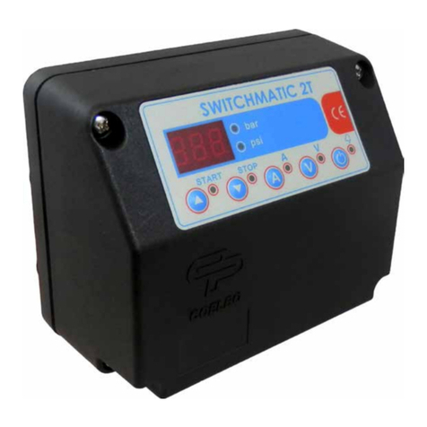
Phase Fail Relay
DFR - 021D [47I]
DEESYS CO., LTD.
Rev. 1 (2020. 11. 20)

PHASE FAIL RELAY
DFR - 021D
■Description
- DFR-021D is a single open-
phase detector that detects and alarms the open phase or load unbalance based
on the current in normal operating state on a three-phase circuit.
- It uses MCT-A31 as the input converter to monitor and detect three phase load current.
- MCT-A31 uses the second current of Main CT as the input and the I/O current ratio is 3,000:1.
■Specification
Category Rating
Product Name DFR - 021D
Control Power AC/DC 100 to 240V, 50/60Hz, <3VA
Rated Input AC 1 to 160A (1'ry current of MCT), 3Phase, 50/60Hz
Reference Current Setting 1.0 to 10.0A (0.1 step)
Unbalance Rate Setting 10 to 90% (1 step))
Start-Lock Time Setting 1.0 to 60.0sec (0.5 step)
Alarm Operation Time Setting 1.0 to 60.0sec (0.5 step)
CT Ratio Setting 5 to 1,000A (5 step)
Alarm Reset Setting Auto Manu
Output Pulse
Setting
Action Mode Pulse Latch
Pulse Retention Time
0.1 to 10.0sec (0.1 step) ㅡ
Motion Precision ± 10% at setting value
Motion Indication LCD blinking red
Insulation Resistance More than 100M Ωwith DC 500V Megger
Insulation Strength 2,000V AC rms 1minute
Surge / Impulse IEC255-4 : 5kV (1.2X50 ㎲) / IEC255-22-1 : 2.5kV (1MHz)
Case Material LUPOY (Black Color) resin
Category Rating
Product Name MCT-A31
Rated Input AC 1 to 5A (2nd current of CT), 3Phase, 50/60Hz
Rated Output 5A : 1.667mA (3,000 : 1)
Insulation Resistance More than 100M Ωwith DC 500V Megger
Insulation Strength 2,000V AC rms 1minute
Case Material LUPOY (Black Color) resin

PHASE FAIL RELAY
DFR - 021D
■Display Screen
Supply the power and you will see the blinking “RUN" sing, and it shows following two screens alternately every
two seconds.
- Shows the average value of the 3 phase input current: 2
seconds
- Shows the current unbalance rate (%): 2
seconds
■SET Menu
1. Reference Current Setting
Press ‘M’key (Menu) to enter into the Reference Current Setting Screen. Then, the 'SET' indicator will blink.
Press the ‘SET’key and ‘CURRENT’will blink. Then, you can change the set values.
‘M’key: Shift
☆SET Range : 1.0 to 10.A (0.1 step)
‘△’ key : value increase
‘▽’ key : value decrease
‘SET’key : value save
- The reference current is the primary MCT current. After the motor start-up, it becomes the reference value
for the stabilized operating current calculation.
2. Unbalance Rate (%) Setting
: Press the ‘▽’ key in the Reference Current Setting to enter into the Unbalance Rate Setting Screen. Then,
the ‘SET’indicator will blink.
: Press ‘SET’key to change the set value.
‘M’key: Shift
☆SET Range : 10 to 90% (1 step)
‘△’ key : value increase
‘▽’ key : value decrease
‘SET’key: value save
- Operates if it exceeds the Unbalance Rate (%) configured based on the Reference Current.

3. Start-Lock Time Setting
: Press the ‘▽’ key in the Unbalance Rate Setting to enter into the Start-Lock Setting Screen. Then, the ‘SET’
indicator will blink.
: The ‘TIME’and the ‘PICKUP’will be on. Press the ‘SET’key to change the set value.
‘M’key: Shift
☆SET Range : 1.0 to 60.0sec (0.5 step)
‘△’ key : value increase
‘▽’ key : value decrease
‘SET’key : value save
- Set the stabilization time upon the motor start-up and Unbalance ‘Operation’will not work within the set
time.

PHASE FAIL RELAY
DFR - 021D
4. Alarm Operation Time Setting
: Press the ‘▽’ key in the Start-Lock Setting to enter into the Operation Time Setting Screen. Then, the ‘SET’indicator will blink.
: The ‘TIME’and the ‘TRIP’will be on. Press the ‘SET’key to change the set value.
‘M’key: Shift
☆SET Range : 1.0 to 60.0sec (0.5 step)
‘△’ key : value increase
‘▽’ key : value decrease
‘SET’key : value save
- Set the Delay Time in case of Unbalance Operation.
5. CT Ratio Setting
: Press the ‘▽’ key in the Operation Time Setting to enter into the CT Ratio Setting Screen. Then, the ‘SET’indicator will
blink.
: The ‘MODE’will be on. Press the ‘SET’key to change the set value.
‘M’key : Shift
☆SET Range : 5 to 1,000A (5 step)
‘△’ key : value increase
‘▽’ key : value decrease
‘SET’key : value save
- Set the CT Ratio of the Motor side.
6. Alarm Reset Setting
: Press the ‘▽’ key in the CT Ratio Setting to enter into the Reset Setting Screen. Then, the ‘SET’indicator will blink.
: The ‘AUTO’or the ‘MANU’will be on. Press the ‘SET’key to change the set value.
‘M’key : Shift
‘△’ key : value increase
‘▽’ key : value decrease
‘SET’key : value save
- When disabling the Alarm, you can select the automatic return or the manual return by pressing ‘Reset’key.

7. Output Pulse Setting
: Press the ‘▽’ key in the Reset Setting to enter into the Output Pulse Setting Screen. Then, the ‘SET’indicator will blink.
: The ‘TIME’indicator will blink and Pulse and Latch will be shown. Press ‘SET’key to change the set value.
‘M’key : Shift
‘△’ key : value increase
‘▽’ key : value decrease
‘SET’key : value save
- If you select the Pulse Output, you need to set the Pulse Retention Time.

PHASE FAIL RELAY
DFR - 021D
8. Pulse Retention Time Setting
: Press the ‘▽’ key in the Output Pulse Setting to enter into the Pulse Retention Time Setting Screen. Then, the
‘SET’indicator will blink.
: The ‘TIME’will be on. Press the ‘SET’key to change the set value.
‘M’key : Shift
☆SET Range : 0.1 to 10.0sec (0.1 step)
‘△’ key : value increase
‘▽’ key : value decrease
‘SET’key : value save
- Alarm output lasts for a set amount of time, and the contact will return.
■TEST Mode
Self-Test Menu is to check the integrity and condition of the circuit operation.
1. Press the SET key and Test key in the front for 5 seconds.
2. ‘TRIP’indicator will be on, and LCD shows blinking red Back light.
☆To prevent malfunction by simple touch, it is
designed to press the button for 5 seconds for
Test implementation.
.
- Please note that the output contact operates simultaneously.
3. Press ‘RESET’key to restore the status display and contacts.
: Only manual return is available for TEST RESET regardless of automatic reset setting.
■Display upon Start-Lock Operation
Upon the Unbalance, start the count for the time set in the Operation Time Setting of the Set Menu.
: The ‘PICKUP’indicator will be on and count from 1 to 9 at x0.1 scale.
...
☆If the Start-up Time is 30 second,
Run the count at 3 sec, the x0.1 scale.
- If the Unbalance is resolved during the Start-Lock count, it goes back to the Display Screen after
counting.

PHASE FAIL RELAY
DFR - 021D
■Alarm Display
1. In case of Unbalance after the Start-Lock Count, start the count for the time set in the Alarm Operation Time
Setting of the Set Menu.
: The ‘TRIP’indicator will be on and count from 1 to 9 at x0.1 scale.
...
☆If the Alarm Operation Time Setting is set at
1 second,
run the count at 0.1sec interval, the x0.1
scale.
- If the Unbalance is resolved during the Alarm count, it goes back to the Display Screen after counting.
2. After Alarm count, the LCD shows blinking red Back light and shows the following three screens alternately every
seconds.
If set to manual return, you need to press the ‘RESET’key to restore.
- Shows the current before the
unbalance : 1 sec.
- Shows the Unbalance Rate (5):
1 sec.
- Show the operation time : 1
sec.
■Wiring

PHASE FAIL RELAY
DFR - 021D
■Dimension
1. DFR-021D
2. MCT-A31
Other DEEsys Relay manuals
