DeFever Hele Mai User manual
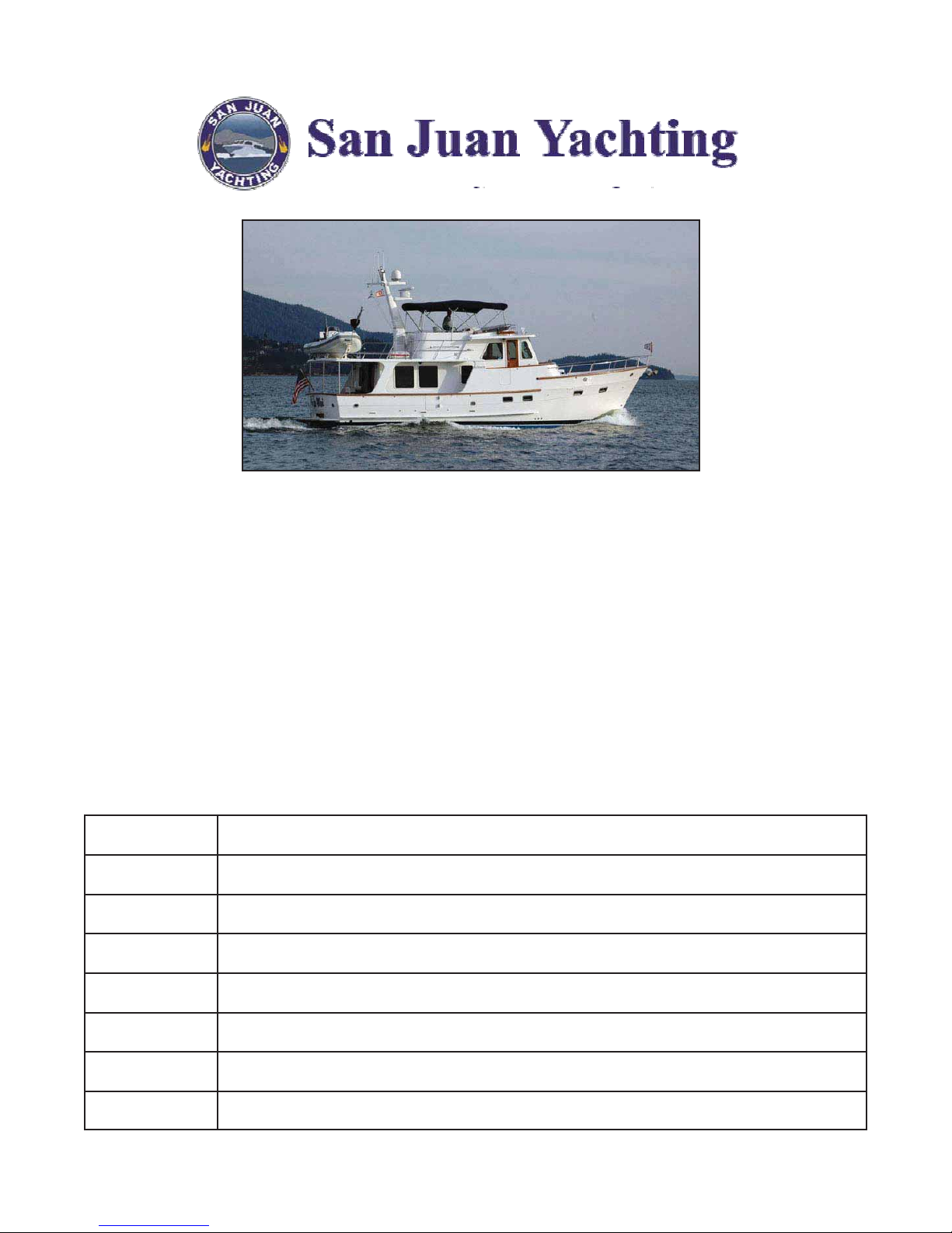
“Hele Mai”
A 46' Defever Ocean Trawler
Operating Manual
Edition of April 7, 2011
Copyrighted. See notice next page
Section Contents
1 Introduction & General Description
2 Important Vessel Numbers
3 Operating Checklists & Maneuvering Suggestions
4 Specific Discussion of Boat Systems
5 “What to Do” for Some Specific Concerns
6EMERGENCY PROCEDURES
7 Index

Copyright 2008, 2010, 2011 Joseph D. Coons. This manual was written for this boat’s owner
by Joseph D. Coons, 1220 Birch Falls Drive, Bellingham, WA 98229, tel (360) 647-0288.
All rights reserved. This manual may not be quoted, copied, or duplicated, in whole or in part,
in printed or electronic form, without express written consent from the author.
About the Author
Joe Coons is a retired AM-FM broadcasting station owner and computer systems corporate
executive who throughout his life was involved in communications and mechanical, electrical, and
electronic systems. He cruised his own boat on the Hudson River and Lake Champlain when a
teen and in his early twenties, and during the 70's and 80's accumulated some 2,500 hours as an
instrument-rated private pilot. Beginning in 1986 he became seriously involved in boating as a
boat owner, subsequently working in a “retirement career” as a broker, also commissioning
vessels, operating a charter fleet, checking out boat charterers, and training new power boaters.
He has held a 50-ton Coast Guard Master’s license, and operated his own boats and a substantial
number of others from 26 to 70 feet in the near-coastal waters of Washington State, British
Columbia, and Alaska. His “helm time” exceeds 8,000 hours. In addition, he has trained hundreds
of boaters in the skills of vessel operation.
Warning!
This notice is a part of this manual, and is placed here to warn you as an owner, crew
member or passenger on this vessel that the author of this manual assumes no responsibility
for any errors or omissions herein, and represents only that the writings and illustrations herein
represent his “best efforts” to provide a comprehensive overview of the vessel, so that it can
be operated by a person who has the necessary experience and/or training to operate such a
vessel given the additional information herein.
You should be aware that this operating manual is provided as a convenience to the
owner(s), crew members and passengers on this vessel, and is not complete in every detail.
Given the complexity of this boat and its systems, there is no way that all conditions,
contingencies, and operating details can be covered, both because of space limitations and
because of ordinary oversight as contingencies are speculated upon by the author. Likewise,
it is possible either through oversight and/or changes in the vessel as a result of additions,
modifications, or deletions to or of equipment since publication of this manual, that items
discussed will operate differently than described, be absent from the vessel, or be added to the
vessel without discussion in this volume.
As a vessel owner, crew member or passenger on this vessel, you are here at your own
risk, and the author of this manual has no responsibility for your actions whatsoever. If you do
not feel competent to undertake any or all operations detailed herein, do not undertake it/them;
get help from a competent person.
I thank you, (and my lawyer thanks you.)
Joseph D. Coons

Section 1: Introduction & General Boat Description
1A: About This Manual
1A1: Manual Objective and Limitations
This manual is intended to introduce you to “Hele Mai”, its systems, and features,
allowing you to operate it with the confidence and self-assurance necessary to enjoy your
cruising vacation to its fullest. It is not intended to replace a basic understanding of
seamanship, including navigation skills, weather interpretation or boat handling. You are
expected to have an understanding of these subjects obtained through other sources,
including training, seminars, reading and perhaps most important, experience.
There is no way that a small manual like this one can answer every question or give you
a solution to every circumstance, foreseen or unforeseen. If you have a question which limits
your understanding or handling of this vessel, ask the owner, a specialist, or contact Keith
Robertson or Craig Cooper; make a list of questions as you read the manual, saving them all
up to ask at one time).
1A2: How the Manual is Organized
The manual is divided into six sections numbered “1" to “6" plus an index (Section 7).
Within each section are subsections lettered “A” to “Z” as required.
In section 4, which deals with the specific information about the vessel’s equipment and
systems, the manual is organized by major categories, such as “Anchor”, “Dinghy, Davit &
Outboard”, “Fresh Water System”, etc.
Note that within “Electrical Systems” are the “AC Electrical System” and
“DC Electrical System” as sub-categories, and within them are such items
that are a part of each, such as “Inverter”, “Generator”, etc.;Likewise, all
electronic equipment is in the “Electronics” section.
A complete index is at the back of the manual in Section 7.
Section 1A: About This Manual 1.1
1B: General Description of this Vessel
1B1: Exterior
General
The Defever 46' Trawler is a
traditional design, with fiberglass hull, cabin,
flybridge, deck and swim step structures,
teak gunwhale caps, and stainless steel
welded fittings and handrails. The window
frames are of aluminum with sliding glass
panes, while the windshield frames are of the
same material. For additional speed and
stability, the boat also has been fitted with a
bulbous bow.
The flybridge overhangs the side decks to provide
protection from inclement weather. A roomy cockpit section
with a storage lazarette beneath is especially useful for
handling the dinghy after it is launched from its davit. The
overhang created by the boat deck extending aft of the
flybridge provides a roomy "veranda" for the boat that is
especially welcome on hot days, or when entertaining with
the aft saloon door is open.
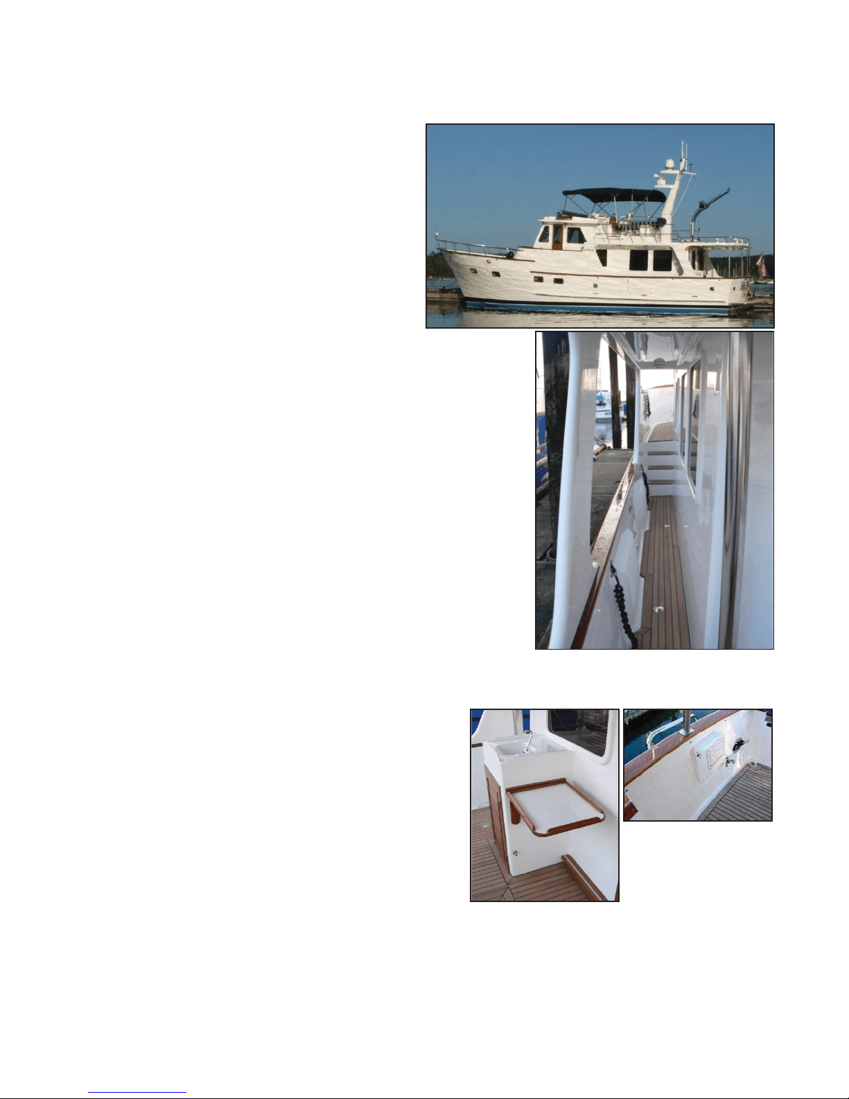
Of particular note are the easy walk-around decks on
each side of the vessel, enabling safe, secure passage
around the boat by passengers and crew. Under the
overhang in the cockpit to port a utility cabinet houses an
icemaker for entertaining.
There are bulwark doors on each side of the boat.
These doors should be closed when docking or rafting, as
they overhang the boat’s side!
The owner has thoughtfully provided special
securing-points for the vessel fenders, with
cam-cleats allowing accurate bumper placement
above the waterline.
On the side decks are four deck plates/fills,
including two fills port and starboard on side decks
for Diesel fuel; an additional two Diesel fills are in
the cockpit for a total of six.
See note on page 4.32 re use
of lazarette fuel tanks!
On the foredeck there is a water fill deck plate, while to starboard is the waste pumpout
deck plate.
Side view of Hele Mai
The starboard aft side deck. Note fender camcleat.
Left: The cockpit cabinet. It has
an icemaker inside.
Above: Swim shower, fresh
water faucet and Cablemaster
switch in cockpit.
Section 1B1: General Description - Exterior 1.2

Forward on the bow deck is the anchor windlass with foot switches allowing chain
movement both "up" and "down" electrically. The anchor retracts into the pulpit which hangs
over the bow to give better clearance from the hull than otherwise possible. After passing over
the winch, the chain goes below decks via a hawse pipe in the foredeck.
A fresh water faucet is on the front of the Portuguese bridge and a salt water washdown
faucet is by the anchor windlass by the bow pulpit. There are coil hoses for each, a sturdy
mooring bit; a water fill inlet to right of the mooring bit, and bow cleats built into the hawse
pipes. The boat is fitted with a Maxwell VMC-2200 windlass that operates the main anchor with
its chain.
The anchoring process for the anchor is expedited using the windlass controls at each
helm station. The anchor rode is marked to inform the skipper how much chain is deployed.
There is a “Cablemaster” shore power cord at the swim step, and forward is a shore
power connection (and an unused TV and phone socket) at the bow; these are selected by a
switch in the electric panel; when power is to be disconnected, the ship AC power circuit
breaker should first be turned to the "off" position to avoid arcing which could damage the plug
contacts. The boat's shore power cable stays with the boat when away from its home dock.
See “AC Electrical Systems” below for shore power requirements.
(Above) The anchor windlass is forward, with foot switches controlling it to its right. Just left of
the windlass is the seawater washdown faucet.
(Right) In this view you can see the mooring bit and the water fill (far right in photo).
The front of the Portuguese bridge. Washdown faucet and pressure inlet to left, shore power
connections to right. Note also the hawse pipe with cleat and fender camcleat.
Section 1B1: General Description - Exterior 1.3

Flybridge:
Above the saloon via the inside
staircase steps from the pilothouse is the
large flying bridge. At the aft end a windlass
on the boat’s davit above the dinghy deck
area allows the boom and line to lift the 12-
foot A-B RIB tender with a 40-horsepower
Tohatsu electric-start outboard.
Forward of the boat deck the flybridge
has a stainless barbecue and an L-settee to
starboard of the mast with under-seat storage
(including a fire extinguisher). In the settee’s
forward compartment are the dual propane
tanks for operation of the stove and barbecue.
Fully forward on the flybridge is the helm structure, with substantial room for engine
controls and instruments plus the ship's full complement of electronics. To port forward on the
flybridge a half-door with sliding hatch above accesses the pilothouse stairway. The door and
hatch are secured both open and closed by sturdy hardware.
A Bimini top covers the flybridge seating area making it a wonderful, shaded area; of
course, the top can be lowered when
weather permits.
Above: The dinghy on the flybridge. It is launched using the crane to right.
Left: The flybridge settee seats four plus the helm seat.
Above: The flybridge console carries a full complement of electronics.
Left: Access to the pilothouse is through the double-door hatch.
Far left top: Propane tanks and storage is beneath the flybridge settee.
Far left bottom: the flybridge carries the emergency life raft.
Section 1B1: General Description - Exterior 1.4

Lazarette
The lazarette beneath the cockpit is
accessed via a large, deck strong hatch in the
cockpit. It holds the furnace and steering
gear, as well as providing storage space for
other items.
The lazarette hatch. Note the steps and teak flooring in picture.
Looking to port inside the lazarette. Rudder gear is under the raised section
of the floor to left. Pipes & valves on the far wall (the boat’s hull to port) are
the rudder hydraulic system, and you can see the autopilot pump.
Between the tanks forward is
one of the boat’s bilge pumps.
Note the neat wiring
arrangement.
This picture shows the net installed to
keep material away from the furnace!
To starboard aft in the lazarette is the Diesel furnace system. The exhaust
pipe is wrapped in protective insulation. Because of fire risk, do not store
anything in this area! See picture below...
Two 50-gallon tanks are in the lazarette, neatly plumbed with sight tank
level gauges.
Section 1B1: General Description - Exterior 1.5

1B2: Main Deck
Saloon:
The boat is entered by either of three doors.
Port and starboard side doors are on the pilothouse (they should be closed when
underway except at very low speeds in calm waters to avoid getting salt water inside the
doorways). The main entry access is the large door at the aft end of the saloon, which opens
onto the cockpit level; with its window and especially when open, it makes the saloon a bright,
airy and pleasant place.
From the cockpit door you are in the beautiful saloon. To port an L-settee seats up to
four; it has a cocktail/dining table in front. The table can be easily opened and expanded to
make it more spacious for dining as in the photos.
Across from this settee are two reclining chairs with a storage cabinet between that also
holds the flat-screen TV and electronic entertainment equipment.
Although the furnishings here appear entirely for comfort, there are important utilitarian
features. Under both ends of the settee are drawers for storage, and under the central part of
the settee’s “L” is the air conditioning air handler for the salon.
Main & Lower Deck Floor Plan
Port side of saloon, looking aft. Table opens up for dining at L-settee.
Starboard side of saloon, looking aft. Note the TV cabinet & recliners.
Section 1B2: General Description - Interior 1.6

Galley:
The ship's galley is just forward of the saloon
area. It includes all that the chef could require
including, of course, range, refrigerator-freezer,
microwave/convection oven, garbage disposer, and
extraordinary storage making the necessities for
long cruises easily kept and quickly accessible.
The boat is fully equipped with utensils,
dishware, and cookware, plus the "little touches" of
place mats, etc.
From the galley the
crew easily serves both the pilothouse for en route
dining, as well as the saloon and its main table, yet
the cooking can be discreetly obscured from view
by the divider making guests more comfortable; and
there is adequate space for
two cooks to work in the
galley.
In addition to the
storage and facilities directly
in the galley "U", the double
door refrigerator-freezer is
across from it in the forward
end of the saloon settee.
The sink is fitted with a garbage disposal activated by a button
on the right top corner of the sink.
The galley has counters, sink, stove, microwave, & compactor in an “L”
arrangement.
Copious storage is provided.
Forward to port past the end of the settee in the saloon is the galley. Note
that the counter serves as a bar with stools.
Another view of the stove and microwave.
Across from the galley is this
roomy refrigerator/freezer.
Section 1B2: General Description - Interior 1.7
1B3: Stateroom (Lower) Deck:
This area of the boat is accessed via the stairway from the saloon.
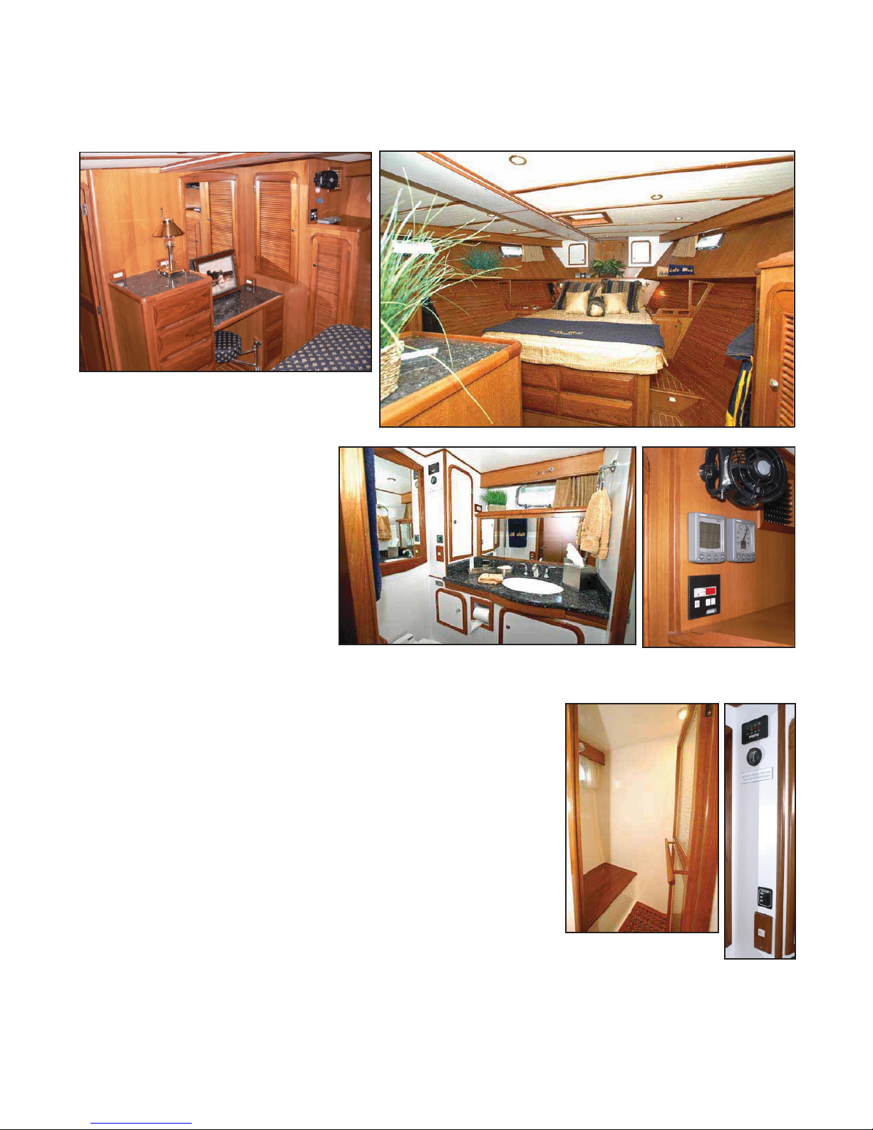
Master Stateroom:
The master stateroom
suite is located forward for
maximum space and comfort.
The island queen berth is
slightly elevated with steps
upon each side. Aft of these
steps are hanging lockers on
each side, and on the aft
stateroom bulkhead there is a
dressing table and dresser with
a swing-out seat.
There are drawers under
the berth’s foot. Under the berth, the mattress panels lift out
to reveal the bow thruster and its battery.
Above the head of the port side of the berth, there is an
intercom phone and a remote control for the ship’s
Westerbeke generator.
Head Compartment:
The head compartment to starboard of the
companionway serves both staterooms, and has a separate
stall shower. It has a granite-topped counter with storage
plus, of course, a toilet, basin, and roomy shower
compartment. There is lots of lighting and an exhaust fan is
provided for ventilation in addition to the porthole. A Y-valve
is under the floor in the guest stateroom (see “Heads” section,
page 4.42).
Master stateroom. Note drawers under berth, hanging locker to starboard.
M/S/R vanity, dressers & hanging lockers, port.
The head compartment. Depth and wind instruments
keep the skipper advised of the
ship’s status at anchor.
Above: The shower stall
Right: The head compartment
has water & holding tank
gauges.
Section 1B2: General Description - Interior 1.8

Guest Stateroom:
Your guests deserve
comfort, too, and Hele Mai
doesn't scrimp for your VIP
guests aboard. The guest
stateroom is to port at the
foot of the companionway
steps opposite the head
compartment. There is a
hanging locker with extra
storage above and below,
and there’s a door for
storage access under the
lower berth. Good lighting
adds to the comfort.
When guests are not
using the berths, they
convert to a settee. The
upper berth swings down
and supporting hardware
secures in a near-vertical
comfortable position.
The boat’s washer-
dryer is also in this
compartment.
Part of the guest stateroom. Note reading lamps and intercom
phone.
In this photo you can see one of the
barrel bolts holding the berth up, as
well as the alternate position for
making it a seat back.
Lots of creature comforts...
The washer-dryer is under the
hanging locker. (Floor is now
carpeted.)
Section 1B2: General Description - Interior 1.9

1B4: Pilothouse Deck
As you saw in the floor
plan, the saloon and pilothouse
are separated from one
another by three steps. The
pilothouse is accessed from
either side deck door, the steps
from the saloon, or the steps
from the flybridge, and is the
nerve center of the boat. The helm offers the
skipper a ringside seat in front of the
remarkably-well-equipped lower helm station, and a
commanding 180-degree view of the boat's
direction and surroundings for easy, comfortable
operation in inclement weather. Just aft of this is a
settee lounge that seats the skipper and two crew
as pilothouse guests.
A table in front of the settee can be used for
navigation and/or food service when eating
underway. Above this lounge a pilot berth provides
nearby accommodation for a standby crewperson.
There are cabinets on each side of the steps
to the pilothouse from the saloon.
The helm itself has an extensive equipment
list including but not limited to main engine controls
and instruments, navigation electronics including
two large LCD displays with autopilot (with a remote
control so the skipper can run from the settee),
anchor windlass controls; stabilizer control, VHF
radio; depth sounder, fresh water usage counter,
and large, clear and complete electrical system
switching and monitoring controls and systems. No
reasonable detail has been overlooked that could
assist the captain in the vessel's safe and efficient
operation.
To port in the pilothouse are the steps leading
up to the flying bridge providing quick and secure
access for crew to this alternate operating area and
prime relaxation spot. Courtesy lights on the face of
each stairway's risers make access at night safe with
glare for the helmsperson. The defibrillator is by
these steps.
The impressive pilothouse panel is the boat’s nerve center.
P/H to stbd: steps down to the saloon and a roomy cabinet.
Pilothouse to port: defibrillator, storage and flying bridge steps.
Section 1B3: Gen'l Description - Engine Room 1.10

1B5: Engine Room
Breakers (third from the
bottom, left row and third from
the top, middle row) in the
ship's DC power panel on the
port side of the helm, and
switches inside and to the left
of the door from the
companionway to the engine
room turn on the engine room
lighting.
The engine room
aboard Hele Mai is accessed
from the aft end of the guest
stateroom. There is adequate
headroom to allow easy
access throughout, and space
is sufficient to get around the
main engines.
The twin, turbocharged John Deere four-stroke
Diesel engines develop 135 horsepower each (maximum)
and drive the vessel via standard shaft arrangements on
each side of the vessel's centerline. The engine starting
and house batteries are outboard and aft of each engine.
The port engine has the stabilizers’ hydraulic pump.
Among the numerous units and systems in the
engine room are Flo-Jet fresh and sea water pumps, an
oil-change system, fuel manifold, sight gauges on the fuel
tanks, dual fuel filters for the main engines and a single
filter for the genset, a hot water heater, dripless shaft
seals, starting, generator and house batteries, sea valves,
sea water strainers, and the watermaker.
At the aft end of the engine room is a Westerbeke
generator yielding 10,000 watts of 230/120 volts AC.
Fuel for the engines and generator is 800 gallons in
six tanks, 400 per side in a 50 gallon lazarette tank, a 100
gallon engine room aft tank, and a 250 gallon engine room
forward tank. A fuel manifold permits tank selection to use
fuel as desired as well as provide for trimming the vessel
(see "Fuel System" , 4.32 for a discussion of fuel
management.)
This is truly a professional engine room up to the high standard of the vessel!
Looking from the forward end of the engine room to aft. Engines in the foreground, door to
lazarette in distance.
Guest stateroom’s door to engine room.
The John Deere 4045 TFM Engine is a quiet modern,
fuel-efficient design.
Section 1B3: Gen'l Description - Engine Room 1.11

1B6: Dinghy & Davit
The boat is equipped with a 12-foot,
center console A-B tender which is a
rigid-Hull, inflatable-pontoon boat and is
fitted with a Tohatsu 40
horsepower two-cycle electric
start-and-tilt outboard motor
and portable fuel tank. For
environmental considerations
and easy fueling, the motor
uses direct oil injection; you
do not mix oil with the fuel,
but you should be sure the
lube oil tank on the front of
the engine is topped off
before use.
The dinghy has a fixed center wheel and upholstered aft
seat and removable forward seat. It is equipped with an electric
bilge pump, built-in fuel tank, automatic bilge pump, trim tabs,
VHF, and Fish Finder.
The davit system uses a stainless steel mast to hoist the
dinghy, using a hoist winch operated by a control that plugs in
when needed. The control is stowed in the helm console cabinet
to port of the helm. The battery switch located under the aft
saloon seat must be on.
See 4.5, paragraph2 regarding water in
the dinghy’s bilge!
1B7: Deck Equipment
The boat has mooring lines; a stern/shore line at least 600' long on a reel in the
lazarette; a 55-pound Delta fast-set stainless main anchor with a 600' all-chain rode (with 350'
marked); a fortress FX-37 emergency anchor with 40' of chain and a rope rode stored in the
starboard lazarette, an anchor bridle stowed in the Portuguese bridge cabinet; bridles for
shackling to a mooring buoy; a boat hook, a boat hook-attached buoy-hooking device;
fenders/bumpers; and a hose for fresh water tank filling and boat washing.
The A-B dinghy on its chocks on the aft flybridge deck. The davit is to right.
Davit control in
cabinet.
The davit main switch is in the aft saloon
settee “L” facia.
Section 1B4, 1B5: Dinghy & Deck Equip. - 1.12

Fire suppression system control
handle.
Life jackets are in cabinet.
The Lifesling is just to stbd of the transom
door. Instructions are on front of the bag.
1B8: Safety Equipment
Life Jackets and flares are in the pilothouse in the cabinet
under the settee just behind the helm seat; more jackets are in a
bag in the lazarette.
This vessel is equipped with fire extinguishers located:
• By the engine room door inside to starboard;
• In the saloon above the refrigerator;
• In the pilothouse by the starboard door;
• In the master stateroom inside the forward starboard hanging locker
• On the flybridge inside the aft seat.
There is an automatic fire suppression system in the engine
room that can be manually operated by pulling a handle on the aft
side of the TV/Stereo cabinet in the saloon.
There is a First Aid Kit in the head compartment cabinet.
There are Carbon Monoxide Monitors and in the master
stateroom forward and on the aft side of the entertainment cabinet.
There are VHF Radios at both helms and there are
handheld VHF radios aboard;
ALifesling rescue system is in the cockpit just to starboard
of the transom door;
An Emergency Life Raft is starboard on the flybridge just
forward of the dinghy;
High Water Alarms check each bilge. See page 4.4.
AFLIR Navigator II thermal imaging system to allow for
nighttime visibility.
ADefibrillator is located above
the pilothouse berth by the door to
the flybridge.
The emergency defibrillator in the
pilothouse by the flybridge steps.
The Life Raft. Instructions are atop it.
Section 1B6: Safety Equipment - 1.13

(Intentionally left Blank)
Section 1B6: Safety Equipment - 1.14

Section 2: Important Vessel Numbers
Vessel Name: Hele Mai
Vessel Official Number: 1207966
Hull ID Number POC46117L708
Capacities:
Sleeps four/five: Two in each stateroom (plus pilot berth if desired)
Fuel: 800 Gallons in six tanks
Fresh water: 250 Gallons in one tank under master stateroom
Holding Tank: 50 Gallons
Dimensions:
Length Overall: 46 feet
Beam: 15 feet
Draft: 5 feet 6 inches
Displacement: 42,000 Pounds full load
Fluids:
Motor Fuel: #2 Diesel
Motor Oil, mains: 15W-40 Chevron Delo Multigrade
Transmission Oil: 30-weight Chevron Delo
Engine Coolant: 50-50 mix, ethylene glycol & water; corrosion inhibitor added
` (Supply on boat already mixed)
Operating Parameters (Estimated):Actual consumption will likely be less.
RPM Speed Total Fuel Consumption Naut. Miles/Gallon
1400 6.5 2.8 2.32
1600 7.2 3.6 2.0
1800 8.2 4.2 1.95
2000 9.1 6.5 1.40
2200 9.5 9.5 1.00
2400* 9.9 12.0 .83
2600* 10.5 14.0 .75
*Speeds over 2340 RPM are limited to no more than 20% of operations (no more than
one hour in five.) No exceptions!
Section 2: Important Vessel Numbers 2.1

(Intentionally left blank)
Section 2: Important Vessel Numbers 2.2

Section 3: Checklists & Maneuvering Suggestions
First Thing Each Day
QCheck engine oil, coolant.
QCheck under-engine oil pads. Okay?
QCheck fuel tank levels, fuel valve settings
QCheck holding tank indicator in head. Need pumping?
QTurn off anchor light if illuminated.
Starting Engines
QAll lines clear of propeller and on deck.
QItems running on AC evaluated vis-a-vis the Inverter and Generator.
QBattery selector switch on “Both”. QAppropriate DC breakers "On".
QThruster breaker and Electronic Engine Control breaker "On".
QShore Power/Generator switch to “Gen”
QDC panel “Stabilizer” breaker must be “ON” before engine start! See 4.45.
QShift levers in “neutral/idle”.
QLift control switch cover, press control selector switch. Neutral lamp “On”.
QEngine key switches "On".
QPush start buttons.
QIf engines do not turn over, see “What to Do If”.
QCenter stabilizers see page 4.45.
Leaving Dock (Only 3-4 minute engine warmup required!]
QAft Side deck bulwark doors closed!
QShore power switch “Off”.
QShore power cord removed, stowed on board.
QFenders hauled aboard and stowed.
QLines and other deck gear secure/stowed.
QDoors and hatches closed and secured as appropriate.
Underway
QHelmsperson on watch at all times. To use stabilizers, see page 4.45.
QRPM under 1400 until engines warm to 140°, extended RPM’s under 2350.
QWake effects always in mind.
If Engines are to be Shutdown or Vessel will be Stopped or Reversed
QPress & hold “Center” on stabilizer control panel & confirm on bar graphs.
Approaching Dock
QPress & hold “Center” on stabilizer control panel & confirm on bar graphs.
QBulwark doors closed & fenders out as appropriate.
QBow line OUTSIDE stanchions and bloused around toward midships.
QEngine dead slow, thruster breakers “On” for maneuvering.
QMate ready to secure stern first (in most circumstances).
Section 3A: Operating Checklists 3.1

After Arriving at Dock in Marina
QAft bulwark doors may be opened if no risk of rolling damage.
QLines secure, including spring lines.
QWater heater breaker off until Inverter current settles (see “Inverters” below).
QShore power cord connected, shore power switch “On” to power location.
QShore power confirmed on meters, Inverter “On”.
QElectric use monitored for current capacity of shore facilities.
Arriving at Mooring Buoy
QPress & hold “Center” on stabilizer control panel & confirm on bar graphs.
QSkipper puts starboard end of swim step, with mate on it, next to buoy.
QMate loops 20' or so line, such as bow line, through buoy ring.
QMate holds two ends together, walks up side of boat to bow of boat.
QWith buoy held close to bow, line secured to each bow cleat through hawsepipe.
Mooring at Anchor
QPress & hold “Center” on stabilizer control panel & confirm on bar graphs.
QAnchor is lowered from pulpit while boat is backed up slowly away from anchor.
QWhen desired chain length out (4:1 or 5:1 scope), windlass is stopped.
QEngine reversed for “count of five” until chain pulls up virtually straight. Note:
The boat is not held in reverse against a taught anchor chain!
Generator Starting/Stopping
QHold “Preheat” switch for 15 seconds, then while holding...
QHold “Start” switch until it starts (if it does not start, repeat “preheat” step)
QCheck starboard side exhaust for water flow.
QAfter one minute for warmup, turn power selector from “Off” to “Gen”.
QStopping: Turn power selector from “Gen” to “Off”, wait 1 minute for cool-down.
QHold “Stop” switch until stopped.
Overnight Checklist in Marina
QAft bulwark doors closed (lest boat should roll).
QShore power “On”.
QInverter “On”.
Overnight at Anchor or Buoy
QAnchor light “On”.
QDC electrical items all “Off” including radios, extra lights, etc.
Upon Arising
QIf at anchor or buoy, Inverter only “On” if necessary.
QStart generator if necessary for battery charging.
QInverter “On” if shore power available or generator running.
QTurn on heat if necessary.
QGo to top of this Hele Mai checklist.
Section 3A: Operating Checklists 3.2
This manual suits for next models
1
Table of contents
Other DeFever Boat manuals

Popular Boat manuals by other brands

Sea Ray
Sea Ray 290 Select FX Owner's manual supplement

Boston Whaler
Boston Whaler 20 Justice Series Operation & maintenance manual

Jeanneau
Jeanneau Sun Odyssey 490 Information & operation manual

Northern Diver
Northern Diver SRE DS320 manual

Bestway
Bestway HYDRO-FORCE 65046 owner's manual

Intex
Intex Seahawk 3 Set manual


Nortik
Nortik Scubi 1 Assembling Instruction

Vanguard Sailboats
Vanguard Sailboats Laser Pro Rigging manual

TALAMEX
TALAMEX TLM200A owner's manual

Cobalt Digital Inc
Cobalt Digital Inc CS3 owner's manual

Maxum
Maxum 2700 SE SPORT EXPRESS CRUISER Supplemental owner's guide

BENETEAU
BENETEAU First 44.7 owner's manual