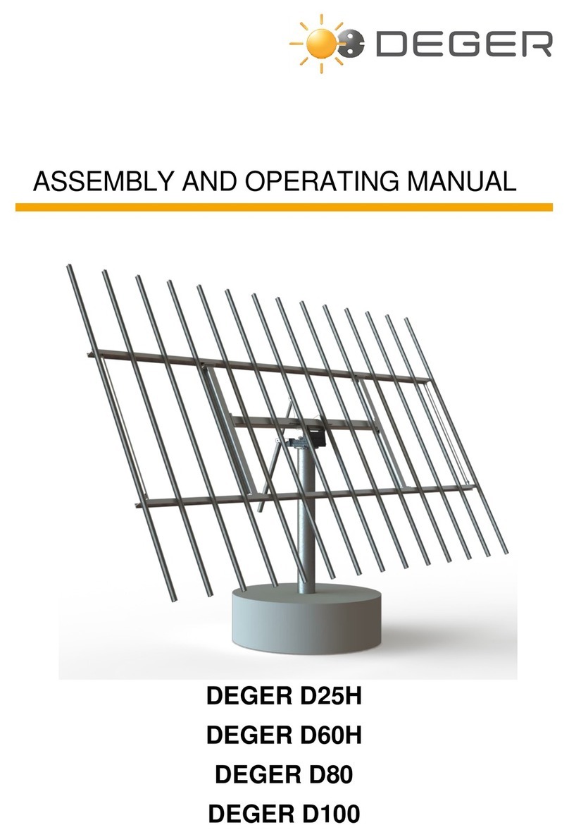
Deger DEGERtracker D60H User instructions

DEGERtracker D60H
DEGERtracker D80
DEGERtracker D100
ASSEMBLY AND OPERATING MANUAL

24.03.2017 ASSEMBLY AND OPERATING MANUAL DEGERtracker D60H, D80, D100 Page 2
© 2017
DEGERenergie GmbH & Co. KG
Industriestr. 70
D-72160 Horb am Neckar
Germany
info@DEGERenergie.com
ALL RIGHTS RESERVED. This manual contains material protected under International and Federal
Copyright Laws and Treaties. Any unauthorized reprint or use of this material is prohibited. No part of this
manual, including drawings and technical descriptions may be reproduced or transmitted in any form or by
any means, electronic or mechanical, including photocopying, recording, or by any information storage and
retrieval system without express written permission from the author / publisher.
We reserve the right for technical changes.
Version: 2017-03-24
Original version in German

24.03.2017 ASSEMBLY AND OPERATING MANUAL DEGERtracker D60H, D80, D100 Page 3
Table of Contents
Abbreviations ................................................................................................................................................. 5
1General....................................................................................................................................................... 6
1.1 Introduction........................................................................................................................................ 6
1.2 Fundamental safety notes ................................................................................................................. 6
1.3 Liability disclaimer.............................................................................................................................. 6
1.4 Symbols used .................................................................................................................................... 7
1.5 Representation rules.......................................................................................................................... 7
1.5.1Enumerations and instructions for actions..................................................................................... 7
1.5.2 Notes on safety.............................................................................................................................. 7
2Product description..................................................................................................................................... 8
2.1 Short description of the DEGERtracker............................................................................................. 8
2.2 Product identification ......................................................................................................................... 8
2.3 For your safety................................................................................................................................... 8
2.3.1 Intended use of the DEGERtracker............................................................................................... 8
2.3.2 Personal protective equipment...................................................................................................... 8
2.3.3 Safety notes................................................................................................................................... 9
2.3.4 Qualification of persons ................................................................................................................. 9
2.4 Scope of delivery ............................................................................................................................. 10
2.4.1 Scope of delivery of the DEGERtracker ...................................................................................... 10
2.4.2 Accompanying documentation..................................................................................................... 12
2.4.3 Optional accessories ................................................................................................................... 12
2.5 Performances to be rendered by the Customer .............................................................................. 12
2.5.1 Material to be provided by the customer ..................................................................................... 12
2.5.2 Machines to be provided by the customer................................................................................... 13
2.6 Technical data ................................................................................................................................. 13
2.6.1 Climatic conditions according to DIN EN 50178:1998-04: .......................................................... 13
3Unloading and intermediate storage ........................................................................................................ 14
3.1 Unloading from truck........................................................................................................................ 14
3.1.1 Notes on unloading...................................................................................................................... 14
3.1.2 Dimensions and weights.............................................................................................................. 14
3.2 Intermediate storage........................................................................................................................ 14
4Abridged assembly instructions for the DEGERtracker ........................................................................... 15
5Preparations for the DEGERtracker assembly......................................................................................... 16
5.1 Notes for preparing the foundation.................................................................................................. 16
5.1.1 Steel Foundation.......................................................................................................................... 16
5.1.2 Mast with wall flange.................................................................................................................... 16
5.1.3 Concrete foundation .................................................................................................................... 16
5.1.4 Creating concrete foundation....................................................................................................... 17
6Assembly of the DEGERtracker............................................................................................................... 18
6.1 Assembling the base frame............................................................................................................. 19
6.2 Assembling the aluminum profiles................................................................................................... 21
6.3 Further preparation.......................................................................................................................... 22

24.03.2017 ASSEMBLY AND OPERATING MANUAL DEGERtracker D60H, D80, D100 Page 4
6.4 Mounting to the mast....................................................................................................................... 23
6.5 Assembling the elevation drive (EMO) ............................................................................................ 24
6.6 Assembly of energy converter 6 (EC-6) .......................................................................................... 24
6.7 Assembly of modules....................................................................................................................... 25
6.7.1 Clamping between modules ........................................................................................................ 26
6.7.2 Clamping at end of module surface............................................................................................. 26
6.8 Preparation to connect the MLD-control to the electrical installation of the customer .................... 27
6.9 Boomerang ...................................................................................................................................... 27
6.10 Grounding the system...................................................................................................................... 28
6.11 Connecting the elevation drive ........................................................................................................ 28
6.12 Overview of cable routing through the gearbox cover plate............................................................ 29
6.13 Assembly of MLD-sensors............................................................................................................... 30
7Install MLD control system ....................................................................................................................... 31
7.1 Connection diagram......................................................................................................................... 31
7.2 Overview.......................................................................................................................................... 32
8Commissioning......................................................................................................................................... 33
9Inspection for free movement................................................................................................................... 33
9.1 Initiate the inspection for free movement......................................................................................... 33
9.2 Scope of the inspection for free movement..................................................................................... 33
10 Declaration of obligation on liability for material defects ..................................................................... 34
11 Optional accessories ........................................................................................................................... 35
11.1 Holding plate for junction box on mast ............................................................................................ 35
11.2 Holding device for inverter on the rotating head.............................................................................. 35
12 Cleaning and maintenance.................................................................................................................. 36
12.1 Cleaning........................................................................................................................................... 36
12.2 Maintenance .................................................................................................................................... 36
12.3 Commodities.................................................................................................................................... 36
13 Spare parts .......................................................................................................................................... 37
13.1 Spare parts catalogue...................................................................................................................... 37
13.2 Contact information for DEGERenergie HQ.................................................................................... 37
13.3 Addresses of service stations.......................................................................................................... 37
13.4 Troubleshooting............................................................................................................................... 38
13.5 Fault message ................................................................................................................................. 39
14 Appendix.............................................................................................................................................. 40
14.1 Declaration of Conformity................................................................................................................ 40
14.2 TÜV Certificate ................................................................................................................................ 41
15 Taking the DEGERtracker out of service............................................................................................. 42
15.1 Disassembly..................................................................................................................................... 42
15.2 Waste disposal ................................................................................................................................ 43
16 Publisher Information........................................................................................................................... 44

24.03.2017 ASSEMBLY AND OPERATING MANUAL DEGERtracker D60H, D80, D100 Page 5
Abbreviations
AZ = Azimuth (East-West alignment)
CCB = Central Control Box
EC-6 = Energy Converter 6 (part of control)
EL = Elevation (inclination angle)
EMO = Elevation drive (motor)
MLD = Maximum Light Detection
MLD control = EC-6, CCB, MLD sensors, wind monitor, snow sensor
OSHA = Occupational Safety and Health Administration
PB = Power Box (part of control)
PPE = Personal Protective Equipment
SW = Spanner Width (wrench size)
UPS = Uninterruptible Power Supply

24.03.2017 ASSEMBLY AND OPERATING MANUAL DEGERtracker D60H, D80, D100 Page 6
1 General
1.1 Introduction
This operating manual has been written for the DEGERtracker systems D60H, D80 and D100. It is part of the
product and must be kept over the entire lifetime of the DEGERtracker. If the DEGERtracker is passed on to
a third party, the assembly manual must also be passed on.
1.2 Fundamental safety notes
This assembly manual must be read completely before the start of assembly work and should always be
available during all assembly work.
Assembly work must only be carried out by qualified specialist personnel.
The total slewing range of the DEGERtracker must be kept free of any objects.
The entire action range of the installed DEGERtracker must be protected against unauthorized access by
applying appropriate measures, e.g. a fence. A clear notice to stay clear of the slewing range is mandatory
and must be attached at the accessing area to the DEGERtracker.
For all photovoltaic systems acc. to DIN VDE 0185 or 0100 the lightning protection and grounding must be
executed according to country specific guidelines.
Operation of the DEGERtracker must not be started without a fully functional wind monitor. The module
surface must be kept in SAFE position (table position), until the function of the wind monitor has been
tested. For more information see assembly instruction “MLD Control EC-6-with CCB”.
If snow has accumulated on the module surface, the module surface must first be cleared. This is
accomplished by manually controlling via the CCB or through the snow sensor (optional for DEGERtracker
D60H). If no functioning CCB and/or snow sensor is available, the module surface must be cleared
manually. The snow sensor shall not release from the clearance obligation of the module surface from
snow.
For the DEGERtracker D60H the max. permissible load is 35 kg/m² (this corresponds with approx. 8 cm
wet snow and approx. 15 cm powder snow).
For DEGERtrackers D80 and D100 the module surface must be cleared if the load reaches and exceeds
10 kg/m² (this corresponds with approx. 2 cm wet snow and approx. 4 cm powder snow).
DEGER recommends an Uninterruptible Power Supply (UPS) to ensure the function of the wind monitor.
1.3 Liability disclaimer
The General Terms and Conditions for Deliveries and Services (GTC) of DEGER are generally valid and
may be accessed on our website at www.DEGER.biz in the publisher information section. The contents of
these documents are continually checked and modified as needed. The assembly manual is also available
for downloading from the website www.DEGER.biz in the dealer section or can be ordered through the
normal sales channels.
Warranty and liability claims for any kind of damage are excluded if they can be traced back to any of the
following causes:
- Inappropriate or unintended use of the DEGERtracker
- Operation of the DEGERtracker in an unintended environment
- Operation of the DEGERtracker while failing to comply with the locally valid statutory safety regulations
- Non-compliance with warnings and safety notes in all documents relevant to the product
- Operation of the DEGERtracker under unsound safety and protection conditions
- Unauthorized changes to the DEGERtracker's design, its component parts or their implementation in the
overall installation
- Malfunction of the DEGERtracker caused by the effect of connected or adjacent devices beyond the
permissible limiting values
- Disaster situations and force majeure
- Operation of the DEGERtracker without proper wind monitors installed
- Installation of non-genuine DEGER replacement parts
- Unauthorized modifications to any parts
- Damages to any third party components (e.g. inverter or modules)

24.03.2017 ASSEMBLY AND OPERATING MANUAL DEGERtracker D60H, D80, D100 Page 7
1.4 Symbols used
The following symbols are used on the DEGERtracker and in this document:
Access for unauthorized persons prohibited
Before starting operation, read and follow the operating manual and the safety notes
1.5 Representation rules
1.5.1 Enumerations and instructions for actions
Enumerations
Enumerations are presented with preceding dashes.
- Enumeration
- Enumeration
Instructions for action in a certain order
Instructions for actions that need to be processed in a certain order are successively numbered.
1. Step 1:
2. Step 2:
Instructions for action without a certain order
Instructions for actions that are not required to be processed in a certain order, are highlighted with
preceding dots:
Instruction for action
Instruction for action
Results
Results of an action are highlighted with a double-arrow:
>> Result
1.5.2 Notes on safety
The following safety notes are used in this document:
______________________________________________________________________________________
DANGER!
Direct endangerment with high risk, failure to comply will lead to fatal or severe physical injuries.
______________________________________________________________________________________
WARNING!
Possible endangerment with medium risk, failure to comply can lead to fatal or severe physical
injuries.
______________________________________________________________________________________
CAUTION!
Low risk endangerment, failure to comply can lead to medium physical injuries.
______________________________________________________________________________________
ATTENTION!
Danger of material damage, when failing to comply with this note.
______________________________________________________________________________________

24.03.2017 ASSEMBLY AND OPERATING MANUAL DEGERtracker D60H, D80, D100 Page 8
2 Product description
2.1 Short description of the DEGERtracker
The DEGERtracker has been designed and dimensioned for use with standard photovoltaic modules. With
its patented control and the patent protected mechanics, the DEGERtracker exactly follows the sun at any
time, or, in the case of a cloudy sky, manoeuvres to the point of highest light intensity. The MLD-control is
designed to work with maximum efficiency and to perform only such movements, which will result in an
immediate increase in yield.
2.2 Product identification
The type plate is attached to the rotating head.
2.3 For your safety
2.3.1 Intended use of the DEGERtracker
DEGERtrackers have been designed for the tracking of photovoltaic modules. They are not intended for any
other use, e.g. concentrated modules, use of mirrors or other purposes.
DEGERtrackers can be used for private or commercial applications. They are suitable for outdoor installation
and building integration.
2.3.2 Personal protective equipment
The customer must provide a sufficient amount of protective equipment for assembly and installation work.
Supervisors must check that this equipment is used.
The following protective equipment is required: The following protective equipment is required:
- Hard hat
- Safety shoes
- Safety gloves
- When working at heights in excess of 1 m, anti-fall measures and PPE to protect against falling.
- Any and all safety equipment and standards to be in compliance with Federal, state, and local codes and
OSHA standards

24.03.2017 ASSEMBLY AND OPERATING MANUAL DEGERtracker D60H, D80, D100 Page 9
2.3.3 Safety notes
The safety notes in the individual sections must be strictly followed.
ATTENTION!
DEGERenergie cannot be held responsible for systems that are not constructed in accordance with
the module configuration layout provided by DEGER together with the order confirmation!
The total module surface is determined in a location related manner with the DEGER planning tool
and must under no circumstances be exceeded.
The dimensions specified in the module configuration layout must be complied with.
ATTENTION!
Once the photovoltaic modules have been mounted on the DEGERtracker, the module surface
must remain in horizontal (SAFE) position.
Operation of the DEGERtracker must only be started, after the wind monitor has been installed and
its function has been checked.
2.3.4 Qualification of persons
All work on the DEGERtracker must be performed by expert personnel, unless other persons have been
specified in the table below.
Apart from a completed education in the specified field, this expert personnel must evidently possess the
following knowledge:
Activities Person
Qualification Knowledge
Transport,
storage Forwarder,
assemblypersonnel
-Proof of load-securing training
- Secure use of hoisting gear and lifting tackle
Preparation of
foundation, concrete
Expert personnel
- Knowledge about the reinforcement of foundations
- Secure use of hoisting gear and lifting tackle
Preparation of
foundation, DEGER
Steel foundation
Expert personnel
- Secure use of tools
- Secure use of hoisting gear and lifting tackle
- Product specific knowledge
Expert personnel
Suitable expert personnel with basic
technical education must be made
available for the mechanical assembly
and disassemblyofthe system.
- Secure use of tools
- Secure use of hoisting gear and
lifting tackle
- Product specific knowledge
Suitable expert personnel with basic
electrical education must be made
available for the electric assembly,
commissioning and putting out of service
of the system.
- Routing of electric cables
- Assemblyof terminal blocks, line protection breakers,
electric components, etc.
- Measuring the effectiveness of electrical
protective measures
- Product specific knowledge
Expert personnel
Suitable expert personnel with profound
technical eduction in the fields of
electrical engineering and mechanics
must be made available.
- Safe handling of tools,
- Routing of electric cables
- Assemblyof terminal blocks, line protection breakers,
electric components, etc.
- Measuring the effectiveness of electrical protective
measures
- Product specific knowledge
Handling,operation,
operating supervision,
simple maintenance,
fault remedy
Owner,
user - Product specific knowledge
Waste disposal Expert personnel
- Correct and environmentallyfriendly
disposal of materials and substances
- Decontamination of pollutants
- Knowledge about recycling
Assembly,
commissioning,
disassembly
Operation,
maintenance,
repair,
troubleshooting

24.03.2017 ASSEMBLY AND OPERATING MANUAL DEGERtracker D60H, D80, D100 Page 10
2.4 Scope of delivery
2.4.1 Scope of delivery of the DEGERtracker
7 6 5 4 8,9,10 27 22,23,24 11,12,13
1,2,3 21 22,23,24 15,16,17 18,19,20 12,14
19,20

24.03.2017 ASSEMBLY AND OPERATING MANUAL DEGERtracker D60H, D80, D100 Page 11
Pos. Item No.
Qty. Name Dimensions Weight Use System
in mm in kg
1 1 Rotating head with central tube
370x750x4040 400 all systems
26100025 18 Bolt DIN933 M16x75 0,2
Enclosed with
rotating head
alle
Systeme
36300010 18 Washer DIN125 A17 0,01
Enclosed with
rotating head
alle
Systeme
43900002 2
Cross-bar 160x250x2420 80 Base frame all systems
5** 2
Longitudinal beam 100x190x** max.155 Base frame all systems
63900004 2
Tie rod 40x20x3820 5 Base frame D100
73900005 2
U-section 60x75x2500 15 Base fame all systems
86100142 16 Bolt DIN933, 10.9 M16x70 0,02
Enclosed with
base frame
all systems
96300010 32
Washer DIN125 A17 0,01
Enclosed with
base frame
all systems
10 6200031 16
Hexagon nut DIN985 M16 0,03
Enclosed with
base frame
all systems
11 6100143 4 Bolt DIN933, 8.8
M12x40 0,04
Enclosed with
base frame
all systems
12 6300009 10
Washer DIN125 A13 0,01
Enclosed with
base frame
all systems
13 6200026 4
Hexagon nut DIN985 M12 0,02
Enclosed with
base frame
all systems
14 6200011 4
Hexagon nut DIN934 M12 0,02
Enclosed with
base frame
onlyD100
15 8100032 1
Bumerang II cpl. 55x90x150 0,4 all systems
16 5500110 2 Multiple-seal M25 0,01
Enclosed with
cable prefabr.
alle
Systeme
17 5500116 1 Multiple-seal M40 0,01
Enclosed with
cable prefabr.
alle
Systeme
18 8100141 1 Control complete EC-6
210x250x290 2 all systems
19 6100095 3 Bolt DIN933 M8x12 0,03
Enclosed with
EC-6
alle
Systeme
20 6300025 2 Washer DIN125 A9 0,01
Enclosed with
EC-6
alle
Systeme
21 4100081 1 Elevation drive T7 80x90x1610 21
all systems
22 6100136 1 Bolt DIN931, 10.9
M20x110 0,04
Enclosed with
elevation drive
all systems
23 6300026 2
Washer DIN125 A21 0,03
Enclosed with
elevation drive
all systems
24 6200032 1
Hexagon nut DIN985 M20 0,07
Enclosed with
elevation drive
all systems
25 6100145 2 Bolt DIN933, 10.9
M14x45 0,08
Enclosed with
elevation drive
all systems
26 3900020 2
Friction bearing shaft Ø30x22 0,01
Enclosed with
elevation drive
all systems
27
* * Alu profile F-Set-D big T-slot *
1.496
kg/m
all systems
28 6900011
* Clamping piece MTH M10 0,08
Aluminum
fastening
all systems
29 6200014
* Hexagon nut DIN934 M10 0,02
Aluminum
fastening
all systems
30 6900235
* Square head bolt M10x35 0,02
Aluminum
fastening
all systems
31
* * End clamp * 0,02
Module
fastening
all systems
32
* * DIN912-A2 M8x* *
Module
fastening
all systems
33 6900007
* Sliding nut M8 20x20x5 0,01
Module
fastening
all systems
34 6300060
* middle plate round Ø25x6.4x3 0,01
Module
fastening
D80,D100
35 6900016 * Centre plate HD 26x50 0,05
Module
fastening
D60H
36 * * DIN912-A2 M6x* *
Module
fastening
all systems
37 6900006
* Sliding nut M6 20x20x5 0,01
Module
fastening
all systems
* The article number, the exact quantity and dimensions depend on the size and type of module configuration.
** Depends on the size of system (D60H, D80, D100)
Article number, exact quantity and dimensions can be found in the delivery note.

24.03.2017 ASSEMBLY AND OPERATING MANUAL DEGERtracker D60H, D80, D100 Page 12
2.4.2 Accompanying documentation
- One assembly and operating manual DEGERtracker
- One assembly and operating manual MLD-control
2.4.3 Optional accessories
Item Article No. Qty. Name Dimensions Weight
in mm in kg
50 1990004
!1
Central Control Boxwith
wind monitor STANDARD
225x350x510
235x285x320
4
2
51 1990003
!1
Central Control Boxwith
wind monitor ADVANCED
225x350x510
235x285x320
4
2
52 1990040 1
Irradiation sensor 80x90x200 1
53 1990014 1
Holding plate for junction box 1.5x250x350 1
54
* 1 Mast * *
55 D60H-FL 1 Mast for building integration 450x5455 430
56 1990008 1
Pendulum holder for wind monitor 100x100x1100 5
57 1900007 1
Snow sensor 130x190x220 1
58 1990400 1 DEGER Steel Foundation
626x600x5000 800
59 1900013 1 Holding device for inverter 600x650 14
60 1900014 1 Holding device for inverter 900x470 15
61 1900015 1 Holding device for inverter 600x470 10
63 1990050 1
Alignment Tool 100x105x125 1
*Article number, dimensions and weight depend on the size of the delivered article.
Article number, dimensions and weight can be found in the delivery note.
!Up to 200 plants can be operated with one Central Control Box and one snow sensor.
2.5 Performances to be rendered by the Customer
2.5.1 Material to be provided by the customer
- Battery pack, 12 to 26 V DC
- Cable straps 3.6x370
- Open end spanner SW 30, 24, 22, 19, 17, 13 and 10
- Torque wrench SW 30 with 200 Nm
SW 24 with 200 and 300 Nm
SW 22 with 195 Nm
SW 18 with 84 Nm
SW 16 with 48 Nm
SW 13 with 24 Nm
SW 10 with 10 Nm
SW 8 with 6.5 Nm
- Screwdriver for slotted-head bolts 0.8x4x100
- Screwdriver for Phillips head bolts PH1
- Appropriate square timbers or metal structure which can hold a load of 2 tonnes as support

24.03.2017 ASSEMBLY AND OPERATING MANUAL DEGERtracker D60H, D80, D100 Page 13
2.5.2 Machines to be provided by the customer
- Hoisting gear to unload transport vehicles (forklift truck, crane, etc.)
- Crane with 4-strand lifting tackle of at least 6 m length, load bearing capacity min. 1500 kg (0-45°), to lift the
rotating head with the mounted base frame
- Ladder, working platform to assemble rotating head, elevation drive and MLD-control. Strict compliance
with national regulations is mandatory
- GPS-receiver or compass
- Cordless drill and cordless screwdriver
2.6 Technical data
D60 H
D80
D100
Nominal output
(depending on module type)
4,000 … 7,000 Wp
6,000 … 10,000 Wp
8,000 … 12,000 Wp
Module surface up to
40 m²
53 m²
70.6 m²
Max. module surface up to (WxH)
8.3 m x 5.3 m
10.05 m x 5.6 m
11.95 m x 6 m
East - West rotation angle
300°
Angle of elevation (horizontal)
0° … 80°
Control
DEGERenergie MLD
IP-protection class
IP 54/CAT 2 / UL50 Type 3R
Input voltage
100…240 VAC /50…60 Hz
Input rated current
0.3 A
Output voltage
24VDC
Max. continuous output current
2.5A
Power nominal Control mode
1 Watt
with running drive
24V / 0.4A / 10 Watt
24V / 0.6A / 15 Watt
24V / 0.7A / 18 Watt
Internal consumption per year
approx.
12 kWh
14 kWh
16 kWh
Drive AZ
Gear in drive head
Rotating speed AZ
30°/min
Drive EL
800 mm lift
Rotating speed EL
13°/min
Sound level
less than 70 dB(A)
Materials
Stainless steel, aluminum,
steel, plastic
Length of mast tube
3.40 m … 8.0 m
3.40 m … 8.0 m
4.0 m … 8.0 m
Weight (without mast/aluminum)
890 kg
930 kg
970 kg
Article No.
MLD-D60H
MLD-D80
MLD-D100
2.6.1 Climatic conditions according to DIN EN 50178:1998-04:
Installation above sea level max. 2,000 m
Permissible ambient temperature -20 °C to +50 °C
Extended humidity range 0 to 95 %
Extended air pressure range 70 kPa to 106 kPa
Snow load DEGERtracker D80 and D100 max. 10 kg/m²
Snow load DEGERtracker D60H max. 35 kg/m²
Dynamic wind pressure 0.5 to 1.35 kN/m² depending on terrain topography, mast
length, module configuration and wind zone.
2.6.2 Permitted tolerances
The horizontal SAFE position (table position) can have a tolerance of ±5°.

24.03.2017 ASSEMBLY AND OPERATING MANUAL DEGERtracker D60H, D80, D100 Page 14
3 Unloading and intermediate storage
3.1 Unloading from truck
3.1.1 Notes on unloading
DANGER!
Danger to life caused by suspended loads!
If heavy parts swing out and fall down they can cause severe or even fatal injuries.
Never step under or into the slewing range of suspended loads.
Move loads only under supervision.
Use only lifting gear and lifting tackle of appropriate capacity for the weight of the component to
be lifted.
Do not use any cracked or torn lifting tackle, like ropes or belts.
Follow the "Transport and loading instructions" accompanying the load.
Ensure adequate free space when unloading parts are up to 10.80 m long.
Take care of eccentric centre of gravity.
Wear hard hat, safety shoes and safety gloves.
WARNING!
Danger of injury by sharp edged parts!
When unloading the parts of the DEGERtracker, sharp edged parts can cause serious hand
injuries.
Wear safety gloves.
The DEGERtracker is delivered in a compact bundled form. Appropriate hoisting gear (forklift truck,
excavator, crane), can be used for unloading at the site and only be operated by trained personnel who have
been specially instructed for this purpose.
3.1.2 Dimensions and weights
The weight of the individual packages can be found in the "Loading list", which is attached to the freight
documents. The centre of gravity and the lifting points for unloading are identified directly on the package.
For the weights of individual assemblies and parts please refer to the chapter "Product description" of the bill
of materials for the scope of delivery.
3.2 Intermediate storage
DANGER!
Danger to life caused by uncontrolled moving parts!
If heavy parts swing out and fall down they can cause severe or even fatal injuries. The tightening
strap for fixing the toggle lever to the rotating head must only be removed after the elevation drive
has been assembled.
ATTENTION!
Remove the pallet from under the rotating head just before assembling the rotating head to the
mast!
If the rotating head is directly placed on the ground, there is a risk that the AZ-drive may be
damaged.
Use a flat surface for intermediate storage. In the case of very soft soil it is highly recommended to place
timber beams under the steel parts.
Strictly comply with the climatic conditions listed in the chapter "Technical data".

24.03.2017 ASSEMBLY AND OPERATING MANUAL DEGERtracker D60H, D80, D100 Page 15
4 Abridged assembly instructions for the DEGERtracker
Read the complete assembly instructions before starting assembly work
Pay attention to all safety notes in the assembly instructions
1.
Erect the mast, install the supply lines
______________________________________________________________________________________
2.
Assemble the base frame
______________________________________________________________________________________
3.
Assemble the aluminum profiles to the base frame
______________________________________________________________________________________
4.
Mount the rotating head to the mast
______________________________________________________________________________________
5.
Assemble the elevation drive (EMO)
______________________________________________________________________________________
6.
Mount the solar modules on the aluminum profiles
______________________________________________________________________________________
7.
Assemble the MLD-control
Exemplary picture
DEGERtracker D100
Exemplary picture
DEGERtracker D100
Exemplary picture
DEGERtracker D100
Exemplary picture
DEGERtracker D100

24.03.2017 ASSEMBLY AND OPERATING MANUAL DEGERtracker D60H, D80, D100 Page 16
5 Preparations for the DEGERtracker assembly
5.1 Notes for preparing the foundation
The foundation must only be prepared by expert personnel.
Documents can be downloaded from www.DEGER.biz in the dealer area.
An empty conduit with pull wire should be provided for routing the cables inside the mast.
When assembling junction boxes or similar, ensure sufficient clearance in the rotating and
slewing range of DEGERtracker and module surface.
5.1.1 Steel Foundation
The Steel Foundation is installed underground. The required ground pressure is at least 150 kN/m². If there
are any uncertainties you must obtain a geological soil report. The assembly instructions "Steel Foundation"
are included in the delivery.
5.1.2 Mast with wall flange
The mast with wall flange has been designed for mounting the DEGERtracker D60H to walls which are
suitable for this purpose. The confirmation of a structural calculation must be available before assembly work
is started.
5.1.3 Concrete foundation
A qualified professional must be commissioned with creating the foundation.
We recommend having the foundation reinforcement approved by a qualified engineer or technician before
concreting.
The necessary bearing capacity of the subsoil is 200 kN/m². This value must be checked for correctness and
documented by the site manager in charge. A substratum expert is to be called in if there is any uncertainty.
In regions and with soils at risk of frost, further measures must be taken to ensure frost protection, e.g. frost-
proof sub-base or lean-mixed concrete fill down to the frost line.
A formwork and reinforcement diagram for the particular foundation, as shown below, can be obtained for
each DEGERtracker on request –you must observe the instructions given in the diagrams! This diagram will
be sent with the order confirmation. The diagram shown is only intended as a sample drawing.

24.03.2017 ASSEMBLY AND OPERATING MANUAL DEGERtracker D60H, D80, D100 Page 17
5.1.4 Creating concrete foundation
1. Excavate top soil, install and affix formwork. Lay wire-
mesh steel into formwork and insert a spacer to ensure
minimum concrete coverage (10 cm). Insert conduit for
cable.
2. Install preassembled bent bar-steel (reinforcement cage)
into the centre of the foundation and insert a mast spacer
centrally (height approx. 5 cm). Please consider to provide
enough space for any conduit runs.
Option 1:
3. Insert mast into the form on top of the mast spacer in
the center of the form. Make sure the borehole in 1.3m
above foundation faces into specified direction (probably
north). Affix mast with 2 reinforcements against rotation.
There is no need to pay attention regarding the positions
of the bores in the flange. The mast must be grounded
with a suitable grounding conductor in accordance to the
local electricity code.
ATTENTION!
The conduit inside the mast must be at least 10 cm above the top edge of the concrete foundation.
Align mast vertically and secure with belts in at least three directions. The mast must be exactly vertical.
Pour out with concrete C25/30 and compact the foundation.
ATTENTION!
Fill up mast up to the top edge of the foundation.
Option 2:
3. Prepare a formwork around the bent bar-steel (reinforcement cage) in the center. The structural integrity of
the formwork should absorb the pressure of the surrounding concrete once pour out. Pour out with concrete
C25/30 (without the area for the bent bar-steel in the center), compact the foundation and allow the concrete
to harden for at least two days.
4. Remove formwork in the center. Insert mast into the middle. Make sure the borehole in 1.3m above
foundation faces into specified direction (probably north). Affix mast with 2 reinforcements against rotation.
There is no need to pay attention regarding the positions of the bores in the flange. The mast must be
grounded with a suitable grounding conductor in accordance to the local electricity code.
ATTENTION!
The conduit inside the mast must be at least 10 cm above the top edge of the concrete foundation.
Align mast vertically and secure with belts in at least three directions. The mast must be exactly vertical. Fill up
the bent bar-steel in the center and mast base up to the top edge of the foundation using grout concrete
C25/30 (flow able) and compact the concrete.
ATTENTION!
Fill up mast base up to the top edge of the foundation.
Use concrete
backfill from
mast base to
foundation top
edge
1,3 m
Borehole for
cable outlet
The concrete should be allowed to harden
for at least 2 days before any further
installation work is done!
Manufacturer’s instruction must be
followed.

24.03.2017 ASSEMBLY AND OPERATING MANUAL DEGERtracker D60H, D80, D100 Page 18
6 Assembly of the DEGERtracker
DANGER!
Danger to life caused by suspended loads!
If heavy parts swing out and fall down they can cause severe or even fatal injuries.
Never step under or into the slewing range of suspended loads.
Move loads only under supervision.
Use only lifting gear and lifting tackle of appropriate capacity for the weight of the component to
be lifted.
Do not use any cracked or torn lifting tackle, like ropes or belts.
Take care of eccentric centre of gravity.
Components may only be lifted by persons who are entitled to work with the required lifting gear.
At wind speeds in excess of 3 m/s all work must be stopped.
Wear hard hat, safety shoes and safety gloves.
DANGER!
Danger to life caused by uncontrolled moving parts!
If heavy parts swing out and fall down they can cause severe or even fatal injuries.
The tightening strap for fixing the toggle lever to the rotating head must only be removed after the
elevation drive has been assembled.
WARNING!
Danger of injury due to of improperly performed assembly work!
Improperly executed assembly work can lead to severe injuries and considerable material damage.
Ensure sufficient assembly space before starting work. Parts are up to 10.80 m long.
The base frame must be assembled on level ground.
Ensure correct assembly. Comply with all specified bolt tightening torques.
For work at heights in excess of 1 m appropriate safety precautions against falling down must be
applied. Use personal protective equipment to protect against falling down.
Wear hard hat, safety shoes and safety gloves.
WARNING!
Danger of injury by sharp edged parts!
When assembling the DEGERtracker, sharp edged parts can cause serious hand injuries.
Wear safety gloves.
DANGER
Danger of injury due to improperly performed assembly work!
Improperly executed assembly work can lead to severe injuries.

24.03.2017 ASSEMBLY AND OPERATING MANUAL DEGERtracker D60H, D80, D100 Page 19
6.1 Assembling the base frame
Upper longitudinal beam
Toggle lever
Central tube U-section
Cross-bar
Cross-bar
Tie rod (only
Tie rod DEGERtracker D100)
(only DEGERtracker
D100) Lower longitudinal
beam
Ratchet strap on toggle lever
(must not yet be removed!)
U-section
1. The pallet under the rotating head must not be removed,
otherwise there is a danger of damaging the AZ-drive. Place
the rotating head with the pallet on level ground.
2. Place appropriate support structure under the corner
points of the cross-bars, as seen in exemplary picture right.
The structure should be levelled to a uniform level of +/-
1 cm.
3. Fasten both cross-bars with four bolts M16x70, washers
and self-locking nuts M16 each to the flange of the central
tube.
Due to the asymmetric arrangement of
holes, the cross-bars cannot be incorrectly
mounted to the central tube.
Tightening torque: 300 Nm

24.03.2017 ASSEMBLY AND OPERATING MANUAL DEGERtracker D60H, D80, D100 Page 20
4. Mount the top and bottom longitudinal beams to the cross-
bars with two bolts M16x70, two washers and one self-
locking nut M16 each.
On the longitudinal beams, the projection of the flange plate
must point downwards!
Tightening torque: 300 Nm
On the DEGERtracker D100, fasten the two tie rods with
the eyelet to the outer bolt connections.
Insert the opposite end through the slot in the U-section and
fix loosely with washer and two nuts M12.
6. Fasten the U-sections to the longitudinal beams with one
bolt M12x40, two washers and one self-locking nut M12
each.
Tightening torque: 84 Nm
7. On the D100, keep turning the nut M12 on to the thread
of the tie rod, until the tie rod, is slightly tensioned.
Do not tighten too much, since this may distort the frame!
The red marked nut is a lock nut.
Tie rod
only with DEGERtracker D100
This manual suits for next models
2
Table of contents
Other Deger Antenna manuals
Popular Antenna manuals by other brands
Winnix Technologies
Winnix Technologies HYN504 product manual
A.H. Systems
A.H. Systems active monopole series Operation manual
SteppIR
SteppIR DB42 MonstIR PRO installation instructions

TeeJet
TeeJet RX510 user guide
Arrow Antenna
Arrow Antenna 52-1BP manual

Chameleon Antenna
Chameleon Antenna CHA TD Operator's manual
AXIOMTEK
AXIOMTEK OPS882 NFC Quick installation guide
DX Engineering
DX Engineering DXE-WA-070 quick start guide
Crest Audio
Crest Audio SGA05331 user manual

Sea Tel
Sea Tel 5012-91 installation manual
Sirio Antenne
Sirio Antenne HP 2070 installation manual
Winegard
Winegard SENSAR III ANTENNA Installation & operation manual
