DeguDent SOLARIS User manual

DeguDent SOLARIS
Name:
Version:
Date:
Page:
Service Manual
1.8
21 Jan 2005
1of 43
DeguDent SOLARIS Service Manual
DeguDent SOLARIS
SERVICE MANUAL
DeguDent SOLARIS
Name:
Version:
Date:
Page:
Service Manual
1.8
21 Jan 2005
2of 43
DeguDent SOLARIS Service Manual
Contents
1INTRODUCTION ...................................................................................................................0
2TECHNICAL SPECIFICATIONS .............................................................................................0
3WARNINGS...........................................................................................................................0
4ASSEMBLY...........................................................................................................................0
4.1 BASIC STRUCTURE ...............................................................................................................0
4.2 VERTICAL DRIVE..................................................................................................................0
4.3 VERTICAL UNIT ....................................................................................................................0
4.4 HORIZONTAL UNIT................................................................................................................0
4.5 STIRRING DRIVE...................................................................................................................0
4.6 HEAD.................................................................................................................................0
5GENERAL WIRING DIAGRAM ...............................................................................................0
6COMPONENT MOUNTING DIAGRAM....................................................................................0
7DATA ADMINISTRATION.......................................................................................................0
7.1 EEPROM DATA...................................................................................................................0
7.2 DETAILS .............................................................................................................................0
8LOCAL OPERATION; GALVANIZATION PROCESS................................................................0
8.1 LOCAL OPERATION ...............................................................................................................0
8.2 GALVANIZING PROCESS.........................................................................................................0
9THE COMMAND INTERFACE................................................................................................0
9.1 OUTPUT AND LOGGING..........................................................................................................0
9.2 COMMANDS.........................................................................................................................0
10 PROGRAMMING INSTRUCTIONS FOR SOFTWARE DOWNLOADS ......................................0
11 TROUBLESHOOTING ...........................................................................................................0
11.1 POWER-UP SELF-TEST......................................................................................................0
11.2 MOTOR PROBLEMS ...........................................................................................................0
11.3 DISPLAY ERRORS .............................................................................................................0
11.4 CONTROL KNOB ERRORS ...................................................................................................0
11.5 HEATER PROBLEMS ..........................................................................................................0
11.6 PROCESS ERRORS ...........................................................................................................0
11.7 ERROR OPERATING DEVICE VIA THE COMMAND INTERFACE......................................................0
11.8 GENERAL ERRORS ...........................................................................................................0
12 PARTS LIST..........................................................................................................................0
13 APPENDIX............................................................................................................................0
13.1 CURRENT ASSIGNMENT RULES IN NORMAL MODE...................................................................0
13.2 CURRENT ASSIGNMENT RULES IN POWER MODE ....................................................................0
13.3 PREPARING FOR CALIBRATION............................................................................................0
13.4 CALIBRATION PROCEDURE FOR CURRENT CORRECTION VALUES...............................................0
13.5 CALIBRATION PROCEDURE FOR VOLTAGE CORRECTION VALUES ...............................................0
13.6 CALIBRATION PROCEDURE FOR CLOSED-CIRCUIT CURRENTS...................................................0
13.7 CALIBRATION PROCEDURE FOR POWER MODE.......................................................................0
13.8 DUAL-LOADING MATRIX .....................................................................................................0
13.9 SERVICE REPORTS ...........................................................................................................0
13.10 DOCUMENTS ...................................................................................................................0

DeguDent SOLARIS
Name:
Version:
Date:
Page:
Service Manual
1.8
21 Jan 2005
3of 43
DeguDent SOLARIS Service Manual
1Introduction
This document describes service-relevant details o the DeguDent Solaris unit and supports the
technician’s troubleshooting efforts. This manual is to be used in connection with the Instructions for
Use, which it will refer to from time to time.
The target group for this document consists of authorized service technicians.
2Technical specifications
Dimensions (W × D × H) Approx. 480 × 270 × 475 mm
Weight Approx. 12.5 kg
Storage and transport
Ambient temperature +10°C to +60°C
Relative humidity 20% to 60% at 35°C
Atmospheric pressure 800 to 1060 hPa
Operation
Ambient temperature +10°C to +45°C
Relative humidity 20% to 85% at 35°C
Height above sea level max. 2000 m
Atmospheric pressure 800 to 1060 hPa
Degree of contamination 2
Operating data
Operation In closed rooms
Protection class I
Protection type, housing IP20
Electrical safety Pursuant to DIN EN 61010 (IEC 61010-1)
including CSA and UL guidelines
Overvoltage category II
Interference suppression Pursuant to EN 55011, limit curve B
Immunity to electrical noise (sound level) Pursuant to EN 50082-2
Mains voltage 100/230 V ±10%
Internal voltage selection
Mains frequency 50/60 Hz
Power requirements Max. 250 VA
Fuses according to IEC 60127 2 × T 2.5 A/H, 5×20 mm
DeguDent SOLARIS
Name:
Version:
Date:
Page:
Service Manual
1.8
21 Jan 2005
4of 43
DeguDent SOLARIS Service Manual
3Warnings
DeguDent Solaris is intended for dental use only.
DeguDent Solaris must be operated using original replacement parts only. This is the only way
to ensure the stated performance and operating safety.
Do not open the unit. Dangerous voltages are present inside.
All maintenance, service and repair work must be performed only by service technicians
authorized by DeguDent.
Protect the unit from moisture to avoid shortcuts and other damage. Do not expose the device
to steam.
Disconnect the device from mains if it is not used for a certain period of time.
Keep Solaris Galvano liquid away from the eyes.
Avoid all contact of Solaris Galvano liquid with skin, eyes, and soft tissue.
Do not swallow Solaris Galvano liquid.
Immediately wash your hands on contact with Solaris Galvano liquid.
Disclaimer
The manufacturer will not assume liability for any damage caused by unauthorized changes or
abuse or other uses contrary to the Instructions of Use.
DeguDent SOLARIS
Name:
Version:
Date:
Page:
Service Manual
1.8
21 Jan 2005
5of 43
DeguDent SOLARIS Service Manual
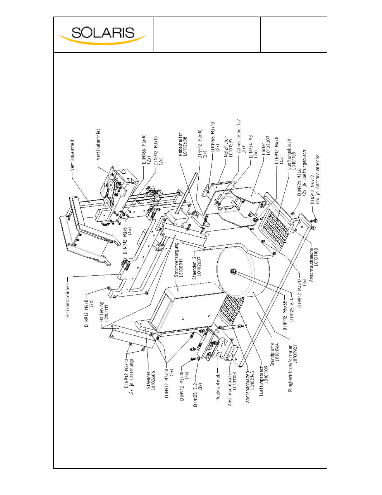
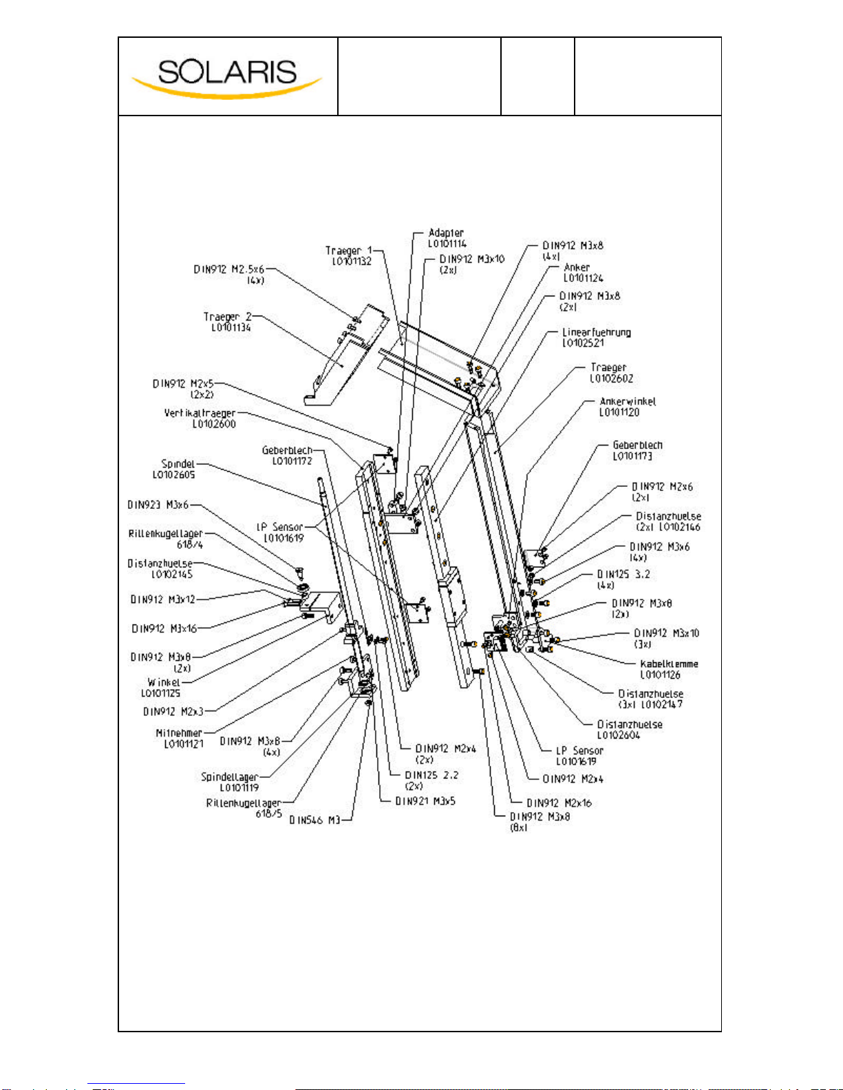
4Assembly
4.1 Basic structure
DeguDent SOLARIS
Name:
Version:
Date:
Page:
Service Manual
1.8
21 Jan 2005
6of 43
DeguDent SOLARIS Service Manual
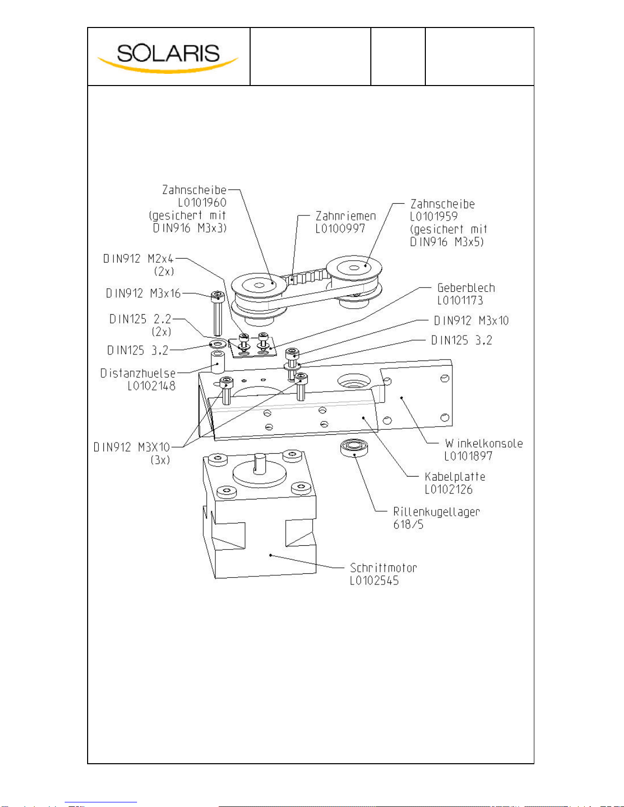
4.2 Vertical drive
DeguDent SOLARIS
Name:
Version:
Date:
Page:
Service Manual
1.8
21 Jan 2005
7of 43
DeguDent SOLARIS Service Manual
4.3 Vertical unit

DeguDent SOLARIS
Name:
Version:
Date:
Page:
Service Manual
1.8
21 Jan 2005
8of 43
DeguDent SOLARIS Service Manual
4.4 Horizontal unit
4.5 Stirring drive

DeguDent SOLARIS
Name:
Version:
Date:
Page:
Service Manual
1.8
21 Jan 2005
9of 43
DeguDent SOLARIS Service Manual
4.6 Head
DeguDent SOLARIS
Name:
Version:
Date:
Page:
Service Manual
1.8
21 Jan 2005
10 of 43
DeguDent SOLARIS Service Manual
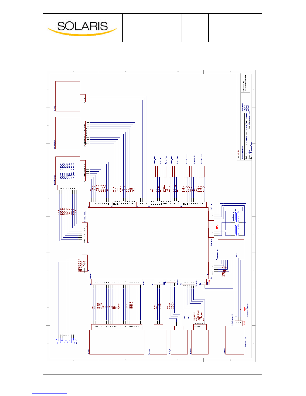
5General wiring diagram

DeguDent SOLARIS
Name:
Version:
Date:
Page:
Service Manual
1.8
21 Jan 2005
11 of 43
DeguDent SOLARIS Service Manual
6Component mounting diagram

DeguDent SOLARIS
Name:
Version:
Date:
Page:
Service Manual
1.8
21 Jan 2005
12 of 43
DeguDent SOLARIS Service Manual
7Data administration
The unit uses non-volatile EEPROM to store important device and process data and to ensure that
data are available across power-on cycles.
7.1 EEPROM data
EEPROM entry Unit Valid range Default
Device-specific values
Unit No. -ASCII, 8 characters Serial number
Current offset, samples (8 x) bit 54 … 250 54
Current offset, ref. electrode bit 109 … 350 225
Current factor, samples (8 x) -0.975 … 1.025 1.0
Current factor, ref. electrode -0.987 … 1.013 1.0
Current offset, Power mode (2/5) bit 0 … 10054
Current factor, Power mode (2/5) -0.90 … 1.00 0.96
Voltage offset, samples (8×) bit 484 … 540 512
Closed-circuit current,
samples (8×) bit 0 … 10 5
Closed-circuit current,
reference bit 0 … 30 15
X-position, rinsing cup increments > 00
X-position, galvanization beaker increments > 040000
Y-position, beaker increments > 0112000
Encoder type (control knob) -0=optical, 1=mechanical 1
DA converter type (control PCB) -0 –new (AD5328)
0xFF –old (MAX5306) 0xFF
Hour counters
Complete unit seconds > 0-
Anode (not used)
Reference electrode (not used)
Heater seconds > 0-
Stirring motor (Motor 3) seconds > 0-
Motor X (Motor 1) seconds > 0-
Motor Y (Motor 2) seconds > 0-
Custom settings
Language -0 –German
1 –English
2 –French
3 –Italian
4 -Spanish
German: 0
Contrast -1…30 10
Units -0 –Standard
1 –U.S. Default: 0
Temperature control
Temperature offset bit Fixed value 72
Temperature factor 1/1000 Fixed value 9660
Electroplating temperature 1/10 °CFixed value 650
Heating rate 1/1000 °C/min Fixed value 1500
Process data

DeguDent SOLARIS
Name:
Version:
Date:
Page:
Service Manual
1.8
21 Jan 2005
13 of 43
DeguDent SOLARIS Service Manual
Recipe data for the last three galvanization cycles
Error history
Last ten error codes with date and time; error counter
When the device is powered up, all the relevant data are read from EEPROM and are available for
program-internal use. If parameters are changed from the menu, the new values are in turn stored.
Recipe data are updated dynamically during preparation and during the galvanization process. The
error history is updated as errors occur.
To ensure the integrity of the data, the EEPROM is secured by a checksum mechanism. Integrity of
the data is checked each time the device is powered up. Any errors are reported to the used and
cannot be cleared except by servicing (see Section 11.1).
7.2 Details
7.2.1 Device-specific values
The device number is the serial number of the device. It is invariably 8 characters long and must agree
exactly with the number on the ID label at the back of the device.
Current-specific correction parameters, Current offset/Current factor, samples, Current offset/Current
factor, reference electrodeand Current offset/Current factor, power mode (channels 2/5)serve to
compensate for the device-specific deviations when converting electric current values (for individual
samples or for the reference electrode) in bit values.
The voltage correction parameter, Voltages offset, Samples serve to compensate for the device-
specific deviations when converting bit values to voltage differences (between the samples and the
reference electrode).
All correction parameters are specific correction factors.
They are determined at a special test station for and stored in EEPROM.
The device is shipped adjusted (delivery setting), ensuring that the device perform within the tolerance
range.
The X-position, rinsing cup and X-position, galvanization beaker position settings define the absolute
horizontal position (increments) of the slide head for lowering into the respective beaker. The criterion
for determining whether the target position is reached when lowering the head is the motor stop as the
head meets an obstacle. This ensures that the beaker is sealed by the slide during processing. The Y-
position, beaker is therefore not to be seen as an absolute position, but as a threshold. If the slide
meets an obstacle before the value is reached, the rim of the beaker is considered to have been
touched. In all other cases, the collision signal is considered to signal motor failure (see 11.2).
The encoder type defines the type of the built-in control knob (mechanical or optical). The fact that the
two are distinguished in the software ensures that they work analogously.
At delivery, this setting will correspond to the hardware installed (delivery setting). If a different
encoder is installed at a later time, a service technician may have to adjust the type setting.
The DAC type defines the type of the DA converter integrated on the control PCB. In order to be able
to react flexibly to the market situation for electronic components, two different types of this
component are supported. Since these differ in the way they are driven, the software looks for
information about the installed type at this EEPROM address. If a different PCB is installed later, a
service technician may have to adjust the type setting.
7.2.2 Hour counters
These counters represent the uptime of the entire device or of individual components. These are
regularly updated while the device is operative. Their value at delivery should not differ significantly
from 0.
DeguDent SOLARIS
Name:
Version:
Date:
Page:
Service Manual
1.8
21 Jan 2005
14 of 43
DeguDent SOLARIS Service Manual
7.2.3 Custom settings
The device has a multilingual user interface. The menu language is determined by the Language
parameter.
Supported languages are English, French, German, Italian and Spanish.
The Contrast setting defines the LCD display contrast.
The Units setting defines the units for displaying temperatures and dimensions:
Default U.S.
Temperature °C °C (°F)
Measurements µm mm
7.2.4 Temperature control
The Temperature offset and Temperature factor correction parameters are used for converting the bit
values at the temperature sensor to a temperature value in°C.
The galvanization temperature is the required process temperature of the galvanization bath
expressed in 1/10°C.
The heating rate defines the maximum temperature increase in the galvanization bath over time during
the heating period in order to protect it from overheating and deposits.
7.2.5 Error history
The error history is a list with the last ten error codes with date and time including the error counter.It
is used for error tracing and problem-driven troubleshooting.
Possible error codes are listed in Section 11.The corresponding time stamp (date/time) is stored in
encode form. The data can be retrieved with a service command via the RS-232 port. The
corresponding error text is output automatically. By way of additional information, the absolute error
counter of the special error code 42 is also logged. Analysis can only be performed by authorized
service technicians.
Examples:
(1) Error History:
15-03-04 12:32:16: error code=41 (Invalid galvanization parameter. Start
current out of range.)
07-03-04 19:04:05: error code=32 (Error reaching clean position. Possibly no
glass on clean position.)
29-02-04 06:21:11: error code=20 (Incomplete recipe found in EEPROM. Previous
galvanisation terminated.)
16-02-04 17:48:55: error code=31 (Error reaching start position. Possibly no
glass on start position.)
13-02-04 08:37:49: error code=36 (Connection failure to all objects.
Galvanisation terminated.)
01-02-04 09:12:36: error code=52 (Error while writing data to EEPROM.)
11-01-04 14:07:00: error code=39 (Invalid galvanization parameter. Object
surface out of range.)
error counter (error code=42)=5
(2) Error History:
(empty)
error counter (error code=42)=0
DeguDent SOLARIS
Name:
Version:
Date:
Page:
Service Manual
1.8
21 Jan 2005
15 of 43
DeguDent SOLARIS Service Manual
7.2.6 Process data
The process data of the last three recipes are stored in EEPROM. A recipe counter that is also
present in EEPROM defines the number of the last recipe applied, facilitating analysis of the relevant
data for errors and process failures due to power outages. The following process data are stored for
each object:
Name Meaning Comment
EnblFlg Indicates whether object is in
use TRUE (1) -Object in use
FALSE (0) -Object not in use
RunFlg Indicates whether process is
active TRUE (1) -Process started (active)
FALSE (0) -Process terminated
(inactive)
ErrVal Type of failure Error during galvanization, see Section 11
SplType Object type (sample type) Subdivision into types 1…8, user selection 1
CurStart Start current [mA]
CurEnd End current [mA] Characteristics of the current curve during
galvanization
Surface Surface [mm²] Object surface including contact surface1
LayerThick Layer thickness [µm] Object-specific, user selection
GoldMass Gold mass [mg] Calculated total mass, object-specific
Location Slot Logical slot number 2
Zone Internal or external slide ring 0 –Internal ring
1 -External ring
CurrentCurrent [mA] Last current value used
GalProcTime Total process time Object-specific
GalProcRstTime
Remaining process time Object-specific
TimeStamp Time of last updated Date/time, can be traced back one month
The sequence of object data corresponds to the physical channel numbers. Data are not accessible
via the local menu but only via the serial command interface. Analysis of the process data can only be
performed by authorized service technicians.
1Object type
Type Surface (mm²) Contact surface (mm²)
150,0
10
265,0
10
387,5
10
4115,0
10
5150,0
10
6200,0
10
7265,0
10
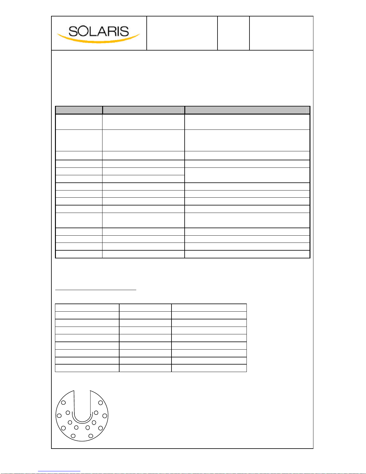
2Logical slot numbers (seen from below):
1
2
3
4
8
7
5
6

DeguDent SOLARIS
Name:
Version:
Date:
Page:
Service Manual
1.8
21 Jan 2005
16 of 43
DeguDent SOLARIS Service Manual
8Local operation; galvanization process
8.1 Local operation
Local operation is described in detail in the Instructions for Use and the Operating Instructions.
8.2 Galvanizing process
8.2.1 Process steps
Parameter menu #1
-For determining the number of electrodes/superstructures
-For turning the automatic divesting process at the end of the
galvanizing cycle on or off
Galvanizing
Go to rinsing position
(automatic divesting if selected)
Parameter menu #2
for defining
-Individual sample layer thickness
-Sample type and surface (manually from table)
àLiquid amount and beaker size display.
Loading
menu
for getting an overview over
-Parameters selected
-Settings for loading, liquid amount and beaker size
Galvanizing menu
with
-Display of remaining time, temperature and status
-
START key.
Go to start position
Galvanizing bath heating
Internal pa
rameter calculation
Connection test
DeguDent SOLARIS
Name:
Version:
Date:
Page:
Service Manual
1.8
21 Jan 2005
17 of 43
DeguDent SOLARIS Service Manual
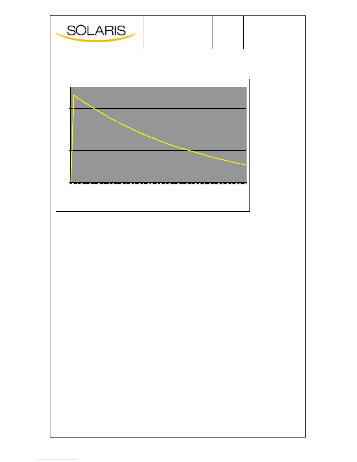
8.2.2 Current curve
For objects not exceeding the surface limits for object type 8, all electric currents during the process
are generated in normal mode. If this is not possible because of the operator’s surface selection,
Power mode is automatically selected, which allows a current output that is approximately four times
higher. The mode can be toggled using the sip service command. Current assignment rules for either
mode are found in the Appendix (see Sections 13.1and 13.2)
0
5
10
15
20
25
30
35
40
45
00:00:00
00:15:38
00:31:38
00:47:38
01:03:38
01:19:38
01:35:38
01:51:38
02:07:38
02:23:38
02:39:38
02:55:38
03:11:38
03:27:38
03:43:38
03:59:38
04:15:38
04:31:38
04:47:38
DeguDent SOLARIS
Name:
Version:
Date:
Page:
Service Manual
1.8
21 Jan 2005
18 of 43
DeguDent SOLARIS Service Manual
9The command interface
An alternative to local operation is operation using a serial command interface. The serial interface
parameters are as follows:
Baud rate: 19,200
Data bits: 8
Parity: None
Stop bits: 1
Flow control: None
There are two types of commands: standard commands and service commands. Servicecommand
are password-protected and require operator authorization.
There are commands
-for parameter and user settings and requests
-for device status requests
-for evaluating recipe data
-for requesting the error history
-…
A detailed command description exist for each command.
The serial port can be accessed using a standard terminal program (e.g. Hyperterminal).
9.1 Output and logging
Depending on the command issued and on the currently running processes, text output may be
available at the serial port. They represent command responses, error messages, information
messages …
9.1.1 Output modes
There are four output modes that determine the amount and type of output received.
Output mode Description
0No output
1Output of galvanization parameters during process
2Comprehensive troubleshooting output
4Minimal output, for internal use only

DeguDent SOLARIS
Name:
Version:
Date:
Page:
Service Manual
1.8
21 Jan 2005
19 of 43
DeguDent SOLARIS Service Manual
9.1.2 Data logging
Events may be logged by activating the logging function of the terminal program (e.g. Hyperterminal).
Data generated by Mode 1 can easily be imported into Microsoft Excel to create diagrams for
visualizing process data.
Data logs are helpful in providing detailed information to service technicians in case of problems.
Creating a data log in Hyperterminal:
-Start data logging, selecting the log file and path
-End of logging; log file is closed

DeguDent SOLARIS
Name:
Version:
Date:
Page:
Service Manual
1.8
21 Jan 2005
20 of 43
DeguDent SOLARIS Service Manual
9.2 Commands
Remotely controlling the device using the command interface is restricted to trained
service technicians, since maladjustment of internal parameters can result in
malfunction of the device including adverse effects on the galvanization process.
Service commands can only be issued after the password-protected service mode has
been activated.
9.2.1 Syntax
Commands are issued as plain text. Parameters are separated by commas.
Command names must be entered in lowercase letters.
Decimals are not supported when entering command parameters.
Command parameters must be whole numbers.
CAUTION:
The parameters of all service commands are based on physical channel numbers. These are different
from the logical slot/sample numbers in the local operating menu.
Either type of numbers can be readily converted to the other type:
Channel
(physical number) Slot
(logical number)
02
14
26
38
41
53
65
77
This list will be output after issuing the rc command.
9.2.2 Standard commands
Command: LS - Service authorization
Command Parameters Explanation and examples
i,<password> Activate service mode (log in)
Example: lsi,<password> -> activates service mode
ls
oLeave service mode (log out)
Example: lso -> leaves service mode
Command: H – Online help
Command Parameters Explanation and examples
hl -Online help: Command overview (standard and service commands)
Command: M – Output modes
Command Parameters Explanation and examples
0Mode 0: No output.
1Mode 1: Output of galvanization parameters during process
2Mode 2: Comprehensive troubleshooting output
m
4Mode 4: Minimal output, for internal use only
!
Other manuals for SOLARIS
1
Table of contents
Popular Medical Equipment manuals by other brands


Barco
Barco Nio Color 5MP user guide

O-Two
O-Two 01MN1000 Operator's manual

Datex-Ohmeda
Datex-Ohmeda S/5 Compact Anesthesia Monitor Technical reference manual

Fresenius Medical Care
Fresenius Medical Care 2008K2 troubleshooting guide

Rosie Connectivity Solutions
Rosie Connectivity Solutions Scan Assembly guide

Albrecht
Albrecht CDS KNEE BRACE FLEXION User instructions