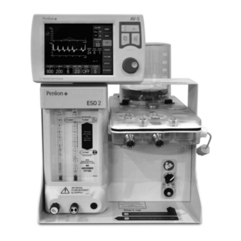
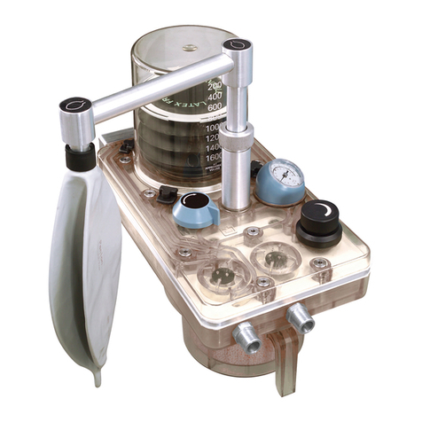
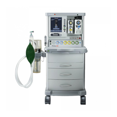
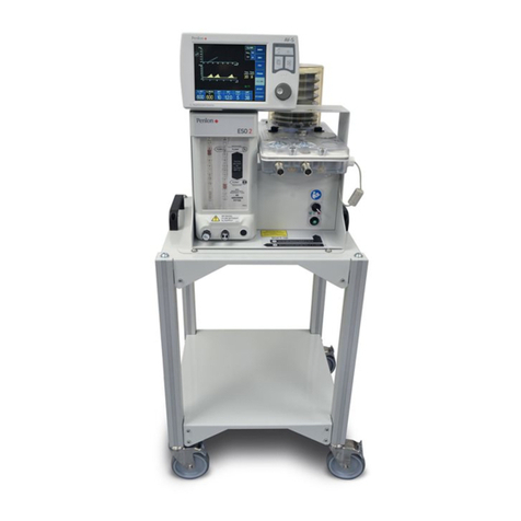
Penlon Prima 320 Advance User manual

Prima 320 Advance Anaesthetic Machine User Manual
ANAESTHESIA SOLUTIONSANAESTHESIA SOLUTIONS


Prma 320 Advance User Manual
IMPORTANT
Servcng and Repars
In order to ensure the full operatonal lfe of ths devce,
servcng by an engneer traned by the manufacturer should
be undertaken perodcally
The machne must be servced to the schedule detaled n
secton 71
Detals of these operatons are n the Prma 320 Advance
servce manual, whch contans servcng procedures etc
Servcng should be carred out by engneers traned by Penlon
Ltd
For any enqury regardng the servcng or repar of ths devce,
contact the nearest accredted Penlon agent
or communcate drectly wth
UK and ROW, except USA
Techncal Support
Penlon Lmted
Abngdon Scence Park
Abngdon, OX14 3NB, UK
Tel +44 (0) 1235 547060
Fax +44 (0) 1235 547061
E-mal techsupportpenloncom
Always gve as much of the followng nformaton as possble
1 Type of equpment
2 Product name
3 Seral number
4 Approxmate date of purchase
5 Apparent fault
NOTE
The seral number can be found on the devce ID label

Prma 320 Advance User Manual
IMPORTANE OF PATIENT MONITORIN
WARNIN
Anaesthesa systems have the capablty to delver mxtures
of gases and vapours to the patent whch could cause nury
or death unless controlled by a qualfed anaesthetst
There can be consderable varaton n the effect of
anaesthetc drugs on ndvdual patents so that the settng
and observaton of control levels on the anaesthesa system
does not n tself ensure total patent safety
Anaesthesa system montors and patent montors are very
desrable ads for the anaesthetst but are not true clncal
montors as the condton of the patent s also dependent
on hs respraton and the functonng of hs cardo-vascular
system
IT IS ESSENTIAL THAT THESE ELEMENTS ARE MONITORED
FREQUENTLY AND REULARLY AND THAT ANY
OBSERVATIONS ARE IVEN PREEDENE OVER MAHINE
ONTROL PARAMETERS IN JUDIN THE STATE OF A
LINIAL PROEDURE
Before usng any montorng system or devce, the user must
check that t conforms to the relevant standards
Ths manual has been produced to provde authorsed
personnel wth nformaton on the functon, routne,
performance and mantenance checks applcable to the Prma
320 Advance anaesthetc machne
Informaton contaned n ths manual s correct at the date of
publcaton The polcy of the manufacturer s one of contnued
mprovement to ther products Because of ths polcy the
manufacturer reserves the rght to make any changes whch
may affect nstructons n ths manual, wthout gvng pror
notce
Personnel must make themselves famlar wth the contents
of ths manual and the machne functon before usng the
apparatus
Foreword

Prma 320 Advance User Manual
Page
1. Warnings and Cautions ................................................................................ 2
2. Purpose............................................................................................. 4
3. Description .......................................................................................... 5
3.1 General Construction.................................................................................. 5
3.2 Gas Circuit ..........................................................................................5
3.3 Front View ...........................................................................................7
3.4 Rear View ...........................................................................................7
3.5 Communication Port ..................................................................................7
3.6 Control Panel ........................................................................................8
3.7 Electrical Power Supply................................................................................ 9
3.8 Vaporizers ..........................................................................................11
3.9 Absorber ...........................................................................................12
3.10 Auxiliary Common Gas Outlet (ACGO) and O Flush control.................................................. 14
3.11 Anaesthetic Gas Scavenge System (AGSS) ...............................................................14
3.12 Ventilator........................................................................................... 15
3.13 Patient monitoring - Parameters .................................................................16
3.14 Alarm system .......................................................................................17
4. Specification........................................................................................ 18
4.1 Physical............................................................................................18
4.2 Gas Supplies........................................................................................ 18
4.3 Gas Supply Pressure .................................................................................19
4.4 Flowmeter Tubes ....................................................................................19
4.5 Auxiliary Oxygen Supply...............................................................................19
4.6 Auxiliary Common Gas Outlet (ACGO) ...................................................................19
4.7 Oxygen Flush .......................................................................................19
4.8 Fresh Gas Mixture ...................................................................................19
4.9 Environmental ......................................................................................19
4.10 Electrical Supply.....................................................................................20
4.11 Absorber and Breathing System .......................................................................20
4.12 Ventilator........................................................................................... 21
4.13 Monitored Parameters................................................................................21
4.14 Alarm Settings ......................................................................................22
4.15 Device Classification and Labelling .....................................................................23
5. Installation and Pre-Use Checks ....................................................................... 24
5.1 Installation and commissioning before first clinical use .................................................... 24
5.2 Absorber Assembly ..................................................................................25
5.3 Connecting Gas Monitoring Modules ....................................................................27
5.4 Installing the Vaporizer ............................................................................... 28
5.5 Gas cylinder installation ..............................................................................28
5.6 Medical Gas Pipeline Connection .......................................................................29
5.7 Auxiliary Power Outlets ...............................................................................29
5.8 Anaesthetic Gas Scavenging System (AGSS) .............................................................29
5.9 Pre-use Test before each clinical procedure..............................................................30
5.10 Vaporizer Tests ......................................................................................34
5.11 Alarm System Tests ..................................................................................35
5.12 Breathing System Test................................................................................38
Contents

Prma 320 Advance v User Manual
Contents
5.13 Oxygen Flush Test ...................................................................................39
5.14 Pre-use Procedure...................................................................................39
6. Operating the Anaesthesia System ..................................................................... 41
6.1 Basic Operations and Settings ......................................................................... 41
6.2 Display Controls .....................................................................................44
6.3 Fresh Gas Settings...................................................................................49
6.4 Ventilation Mode..................................................................................... 50
6.5 Monitoring Parameters ...............................................................................60
6.6 Pulmonary Function..................................................................................60
6.7 Alarm Setup ........................................................................................61
6.8 Trends .............................................................................................61
6.9 Replace Absorbent...................................................................................62
6.10 Auxiliary Common Gas Outlet (ACGO) ...................................................................63
6.11 Alarms.............................................................................................63
7. Maintenance........................................................................................ 67
7.1 User Maintenance ................................................................................... 67
7.2 Cleaning and Disinfection .............................................................................68
7.3 Absorber and Breathing System Components ............................................................70
7.4 Cleaning and Disinfection Methods .....................................................................75
7.5 Absorber and breathing system ........................................................................ 77
7.6 Pressure Sensor Zeroing..............................................................................78
7.7 Flow Sensor Zeroing .................................................................................78
7.8 Oxygen Concentration Calibration ...................................................................... 79
7.9 Touchscreen Calibration ..............................................................................80
7.10 Prevention of Water Build-up .......................................................................... 80
7.11 Battery Replacement .................................................................................80
7.12 Fault Diagnosis and Troubleshooting....................................................................81
8. Appendix ................................................................................................ 82
Appendix 1 References....................................................................................... 82
Appendix 2 Disposal at end of useful life: Risk assessment......................................................... 82
Appendix 3 Optional extras and approved accessories .............................................................82
Appendix 4 Labelling ........................................................................................ 83
Appendix 5 Sidestream CO module (optional)....................................................................85
Appendix 6. Electromagnetic compatibility (EMC).................................................................87

Prma 320 Advance 1 User Manual
Ths devce has been bult to conform wth the specfcaton
and operatng procedures stated n ths manual and/or
accompanyng labels and notces when checked, assembled,
operated, mantaned and servced n accordance wth these
nstructons
To ensure the safety of ths devce t must be checked and
servced to at least the mnmum standards lad out n ths
manual A defectve, or suspected defectve, product must not
under any crcumstances be used
The user must accept responsblty for any malfuncton whch
results from non-complance wth the servcng requrements
detaled n ths manual
Addtonally, the user must accept responsblty for any
malfuncton whch may result from msuse of any knd,
or non-complance wth other requrements detaled n
ths manual
Worn, broken, dstorted, contamnated or mssng components
must be replaced mmedately Should such a repar become
necessary t s recommended that a request for servce advce
be made to Penlon Lmted or the nearest Penlon Servce
entre
Ths devce and any of ts consttuent parts must be repared
only n accordance wth wrtten nstructons ssued by
Penlon Lmted and must not be altered or modfed n any
way wthout the wrtten approval of Penlon Lmted
The user of ths equpment shall have the sole responsblty
for any malfuncton whch results from mproper use,
mantenance, repar, damage or alteraton by anyone other
than Penlon Lmted or ts apponted agents
USA and anadan Federal Law restrcts the sale and use of
ths devce to, or on the order or, a lcensed practtoner
User Responsibility
Statements n ths manual preceded by the followng words
are of specal sgnfcance-
WARNIN
means there s a possblty of nury to yourself or others
AUTION
means there s a possblty of damage to the apparatus
or other property
NOTE
ndcates ponts of partcular nterest for more effcent
and convenent operaton
The reader must take partcular notce of the warnngs,
cautons and notes provded throughout ths manual

Prma 320 Advance 2 User Manual
The followng WARNINS and AUTIONS must be read and
understood before usng ths machne
WARNINS
1 Ths anaesthetc machne system s desgned for use only
wth non-flammable anaesthetc agents It must not be
used wth or n close proxmty to flammable anaesthetc
agents, due to a possble fre or exploson hazard
2 Exteror panels must not be removed by unauthorsed
personnel and the machne must not be operated wth
such panels mssng Unauthorsed personnel must not
attempt to access fuses or other electrcal components
There s a possble electrc shock hazard
3 To solate the machne from the mans power supply,
dsconnect the mans cable from the hosptal power
outlet
4 Always use a mans power outlet socket that can be easly
accessed
5 No ol, grease or other flammable lubrcant or sealant
must be used on any part of the machne n close
proxmty to medcal gas dstrbuton components
There s a rsk of fre or exploson
6 When you attach or remove a medcal gas cylnder
a) Follow approprate manual handlng gudelnes when
lftng
b) Ensure that the machne yoke and cylnder faces
are dust free and clean and that the sealng washer
provded s n poston between the cylnder valve and
the yoke
c) Tghten the yoke securely before openng the cylnder
valve Dust and drt presents a fre hazard n the
presence of hgh pressure gas Leakage of hgh
pressure gas can cause serous nury
7 The machne must be connected to an anaesthetc gas
scavengng system (ASS) to dspose of waste gas and
prevent possble health hazards to operatng room staff
Ths requrement must be observed durng test
procedures as well as durng use wth a patent
8 Ths devce must only be used wth Selectatec-compatble
vaporzers nstalled on the Selectatec-type backbar
system
Free-standng vaporzers may be accdentally tpped,
resultng n excessve and uncalbrated volumes of
anaesthetc drug enterng the breathng system
9 Do not nstall or connect any vaporzers of any descrpton
between the auxlary common gas outlet (AO) and the
breathng system unless they are specfcally desgned for
such use
(If ths s done, the oxygen flush flow wll pass through the
vaporzer and may result n gross overdosage when the
flush valve s operated)
10 Ventlatng Neonatal and Paedatrc patents
a) IMPORTANT
Use ONLY Volume ontrol or Pressure ontrol
ventlaton for mandatory ventlaton of neonates
b) IMPORTANT
Swtchng ventlaton modes durng a clncal procedure
The ventlator wll automatcally revert to the
settngs that were last used n the mode that you are
about to use
To protect the neonatal/paedatrc patent from adult
ventlaton settngs, always swtch to Standby before
swtchng ventlaton modes
Set approprate neonatal/paedatrc parameter
values for the mode that you are about to use, before
recommencng ventlaton
c) Always set a low target pressure frst and then ncrease
to the requred level
d) Use breathng crcuts and flters specfcally desgned
for neonatal/paedatrc use
e) Do not ventlate pre-term babes wth a brth weght
below 24 kg
11 Only vaporzers wth the Selectatec-compatble nterlock
functon wll nterlock f nstalled on a two staton or three
staton manfold
The nstallaton of non-nterlock vaporzers allows the
possble operaton of more than one vaporzer at the
same tme
12 The breathng system whch conveys gases from the
anaesthesa system to the patent and dsposes of
expred gases s a vtal part of the anaesthetc delvery
system Because breathng systems requre frequent
cleanng and dsnfecton they are not a permanent
part of the anaesthesa system and therefore cannot be
drectly under the control of the anaesthetc machne
manufacturer When mechancal ventlaton s employed
the patent breathng system must be connected drectly
to an over-pressure relef valve to prevent the possblty
of barotrauma
13 Always perform a pre-use check of the system, ncludng
vaporzers, ventlator, absorber and montors before
clncal use Follow the pre-use checklsts (see sectons
59 to 514) before each clncal procedure as a mnmum
requrement
Many clncal ncdents occur because of a falure to check
for correct functon
14 The anaesthesa system must not be used f any of the
alarm, montorng or protecton system devces are not
functonng correctly
15 The gas supply falure systems wthn the anaesthesa
system wll not necessarly operate as ndcated n ths
manual durng any procedures that are outsde the scope
of the ndcatons for use of the machne
1. Warnings and Cautions

Prma 320 Advance 3 User Manual
Do not use the system solely to provde large flows of
oxygen, va the auxlary gas outlets, to external devces
whch may not be equpped wth a supply falure alarm
16 The system must not be ftted wth more than three
operator accessble mans socket outlets There s a
rsk of an excessve leakage current Ths can result n a
reduced level of safety
17 Be aware that when equpment s connected to an
auxlary outlet, a medcal electrcal system s created as
defned n IE 60601-1-1 (Refer to auton 8)
18 On machnes wth ppelne connectons, be aware that a
malfuncton of the central gas supply wthn your faclty
may cause mmedate cessaton of gas delvery and total
anaesthesa system falure
19 The use of antstatc or electrcally conductve breathng
hoses s not recommended when usng hgh frequency
electrcal surgery equpment (eg Dathermy) Burns
may be caused
To avod the rsk of electrc shock, ths system must only
be connected to a mans supply wth a protectve earth
Before any electrcally powered machne s used clncally
for the frst tme, check that the hosptal engneerng
department has carred out an earth contnuty test
20 Before usng any addtonal electrcal equpment powered
by the auxlary sockets on the machne, a traned
engneer must check that the addtonal equpment s
correctly wred and s earthed through ts plug
In the event of malfuncton of any devce powered by the
auxlary sockets, a traned engneer must check the
devce and machne fuses
21 A mssng or defectve protectve earth conductor may
ncrease earth leakage currents to the patent to values
exceedng the allowable lmts, resultng n ventrcular
fbrllaton, or nterference wth the pumpng acton of the
heart
22 Portable RF communcatons equpment (ncludng
perpherals such as antenna cables and external
antennas) should be used no closer than 30 cm (12
nches) to any part of ths devce, ncludng cables
specfed by the manufacturer Otherwse, degradaton of
the performance of ths equpment could result
23 Addtonal equpment placed on the top shelf must be
securely attached
Take care when movng a fully loaded machne,
partcularly when negotatng ramps
heck that hoses or power leads are not tralng on the
floor
24 Accessores must be removed before the machne s
transported
25 MRI compatblty - The Prma 320 Advance s not MRI
compatble
26 To prevent patent nury n the event of total anaesthesa
system falure, an alternatve means of ventlaton must
be avalable whenever the devce s n use
27 The Apnea alarm s a vsual, onscreen alarm (no audo
functon), and s actve only n SPONT/PSV mode
28 User mantenance
User Mantenance s restrcted to cleanng the external
surfaces of the machne (see Secton 72)
All other mantenance and servcng and the replacement
of components, ncludng fuses and the mans electrcal
cable, must be carred out only by Penlon-traned
engneers
AUTIONS
1 Flowmeter needle valves are desgned to seal wth lght
torque and may be damaged f tghtened excessvely
Do not force the control knob past ether the fully open or
fully closed postons
2 Open cylnder valves slowly to avod damage to pressure
reducng valves
Ensure that cylnder valves are at least one full turn open
when n use
3 Do not use anaesthetc agents for cleanng purposes
4 After use, always dsconnect the machne from the pped
gas supply and/or close the gas cylnder valves
5 Ant-hypoxc devce (AHD) system - The oxygen flow
control s restrcted to prevent the needle valve from fully
closng Ths ensures a mnmum basal flow of oxygen
DO NOT attempt to close the flow to zero
Do not overtghten
6 ompressed gas supples must be clean and dry
7 When the auxlary gas outlets are n use on a machne
usng cylnder supply only (e If the ppelne supply s not
n use), check flow rate requrements, and ensure that
adequate back-up cylnders are avalable
8 The requrements of IE 60601-1-1 apply to any devce
connected to the auxlary electrcal sockets Users must
be aware of the rsks of ncreased leakage currents when
equpment s connected to the auxlary power sockets
9 Do not apply excessve pressure to the dsplay screens
10 onnect the external OMMS outlet only to approved
devces usng protocol provded by Penlon Ltd ontact
Techncal Support Department for detals
11 Vaporzers Read the nstructon manual suppled wth
the vaporzer before clncal use
NOTE
1 Refer to Appendx 3 for labellng and symbols
Warnings and Cautions

Prma 320 Advance 4 User Manual
Purpose
The Prma 320 Advance anaesthetc machne s for use by a
professonal operator n a professonal hosptal or clncal
envronment, and must be contnually attended when n use
The devce s ntended to provde controlled concentratons
and flows of anaesthesa gases nto a patent breathng
system, from where the anaesthesa ventlator and breathng
crcut wll then delver ths fresh gas mxture to the patent
Use the devce n conuncton wth anaesthetc vaporzers,
breathng hoses and patent connecton fttngs whch comply
wth the relevant ISO standard or equvalent
Dependng upon the patent crcut selected, the machne can
be used n open, sem-open, sem-closed or closed crcut
confguratons
Intended patient population
This product is intended for a patient population from neonatal
(infants) to adult.
as supples
Three gases - oxygen, ntrous oxde, and ar
Pn-ndex cylnder yokes, and provson for up to three ppelne
supply nlets
Backbar manfold for Selectatec-compatble type vaporzers
Ant-Hypoxc Devce (AHD)
The AHD system s desgned to mnmse the rsk of a hypoxc
mxture reachng the patent
2. Purpose

Prma 320 Advance 5 User Manual
3. Description
3.1 General Construction
Frame
The machne has an alumnum base, extruded alumnum
uprghts, and alumnum and plastc mouldngs
Moblty
Four castors wth a brake on each front castor
A footrest s bult nto the front of the machne
Mountng Brackets
A mountng system s bult nto each par of sde uprghts, to
allow the use of mountng brackets for accessores
Work Surface and Lghtng
The work surface has rased edges to retan nstruments, vals
etc
An LED lghtng unt, provdes work-area lghtng The swtch s
located under the top shelf, above the dsplay screen
Extractor Fan Outlet
AUTION
Do not obstruct the extractor fan outlet (1)
3.2 Gas Circuit
The machne has ppelne (2) and cylnder (3) gas nlets
The user sets the requred flows and mxed gas s then
suppled to the vaporzer backbar
The ventlator s a pneumatcally drven, mcroprocessor-
controlled anaesthesa delvery system The drve gas s
suppled by the O or Ar gas supply, see secton 312
A gas crcut schematc s shown on the next page
3
2
1

Prma 320 Advance 6 User Manual
Description
as rcut Schematc
1 O pipeline inlet 23 Exhalation valve - ventilator
2 O cylinder inlet 24 Bellows - ventilator
3 Air pipeline inlet 25 Positive end-expiratory pressure (PEEP) valve
4 NO pipeline inlet 26 Non-return valve
5 NO cylinder inlet 27 Restrictor
6 Pipeline supply filter 28 ACGO control
7 Cylinder supply filter 29 Manual bag
8 Pressure gauge - pipeline 30 Adjustable pressure limiting (APL) valve
9 Pressure gauge - cylinder 31 Manual/mechanical ventilation switch
10 Regulator (350 – 400 kPa) 32 Expiratory non-return valve
11 Non-return valve 33 Absorber canister
12 Non-return valve - cylinder supply 34 Inspiratory non-return valve
13 Regulator (250 kPa) 35 Oxygen sensor
14 Cut-off valve 36 Airway pressure gauge
15 O flush button 37 Expiratory flow sensor
16 Flowmeter assembly 38 Inspiratory flow sensor
17 Bypass valve on backbar 39 Outlet to gas scavenging system (AGSS)
18 Vaporizer 40 Patient
19 Vaporizer 41 Connector - gas scavenging system
20 Regulator (250 kPa) - ventilator 42 Auxiliary oxygen supply
21 Inspiratory flow control valve - ventilator 43 Pressure sensor
22 Over-pressure valve (100 kPa) - ventilator

Prma 320 Advance 7 User Manual
Description
3.3 Front View
1 astors (wth brakes)
2 Anaesthesa system swtch
3 Pressure gauges
4 Dsplay screen
5 Vaporzer
6 ommon as Outlet (AO) and O flush button
7 Multfuncton control
8 Auxlary oxygen supply outlet
Refer to Appendx 3 for detals of a Penlon O therapy
flowmeter kt
9 Absorber assembly
3.4 Rear View
1 ylnder yoke
2 Multple socket outlets
3 Mans nlet
4 ommuncaton port (see secton 35)
5 Battery box cover
6 Medcal gas ppelne supply nlets
7 Extractor fan outlet
3.5 Communications Port
1 albraton and software upgrade port - desgned for use
by traned Penlon engneers only
2 RS232 Interface
onnect the nterface only to approved devces usng
protocol provded by Penlon Ltd
ontact Techncal Support Department for detals
3 VA port - not functonal on all models
9
3
1
4
5
6
7
2
8
61
2
5
4
3
7
1 2 3

Prma 320 Advance 8 User Manual
Description
3.6 Control Panel
1 Multfuncton control knob
Push the control knob to select a menu opton or confrm
your settng
Turn the control knob clockwse or counterclockwse to
scroll through the menu optons, or to change a settng
2 Mans electrcal supply ndcator
3 Power status felds
Orange The anaesthesa machne s connected to an A
power source, and the battery s beng charged
reen The system s operatng on battery power
4 Start/Standby
Press the key to enter standby mode, or to ext standby
mode and start ventlatng the patent
5 System
6 Alarms
7 Trends
8 Montorng
9 Modes
Alarm slence key
Press the key to set a 120-second alarm slence perod
The alarm slence symbol and a 120-second countdown
sequence appear to the left of the Date/tme dsplay
NOTE
The O Supply Falure alarm s not slenceable
10 Date/tme dsplay
11 On/off swtch - work surface lghtng
2
1
12
6
10
11
9
7
8
5
4
3

Prma 320 Advance 9 User Manual
Description
3.7 Electrical Power Supply
3.7.1 Mains power supply
WARNIN
Always use a mans power outlet socket that can be
easly accessed
To solate the machne from the mans power supply,
dsconnect the mans cable from the power outlet socket
Power s suppled to the machne va the mans cable (1) at the
rear upper panel
3.7.2 Auxiliary mains power supply sockets
urrent leakage
AUTION
The requrements of IE 60601-1 apply to any devce
connected to the auxlary sockets (2) Users must be aware
of the rsks of ncreased leakage currents when equpment s
connected to the auxlary mans power sockets
NOTE
It s the user’s responsblty to ensure that the total sum of
leakage currents from addtonal equpment plugged nto the
auxlary sockets plus the leakage current from the machne
does not exceed the values specfed n any relevant natonal
standards that may apply n the country where the machne s
n use
3.7.3 Battery
A back-up battery automatcally provdes power to the
machne n the event of an A mans power falure
AUTION
1 Use the battery at least once every month
2 Battery lfe depends on how often and how long the
battery s used A properly mantaned and stored battery
has a lfe expectancy of approxmately 2 years
Replace the battery every 2 years
3 In case of battery falure, a replacement battery must
be ftted by a traned engneer The user must not ft the
replacement battery
4 When the anaesthetc machne s connected to the A
power source, the battery s charged regardless of
whether or not the system swtch s on
5 If a battery has been dscharged and/or has been stored
for a long tme, chargng may take longer than 4 hours
2
1

Prma 320 Advance 10 User Manual
Description
Backup Tme
A fully charged battery wll power the anaesthesa machne for
up to 90 mnutes, dependng on confguraton and operaton
For example, frequent use of montorng modules wll shorten
the backup tme avalable
Battery Recharge
The battery is charged automatically when the machine is
connected to an AC power source.
Recharge tme Approxmately 4 hours from total dscharge
AUTION
heck every month and fully charge the battery f necessary
Battery Lfe
Battery lfe depends on frequency and perod of use
We recommend that the battery s replaced every 2 years
3.7.4 On-screen power status and battery indicators
On-screen power status ndcator
AC power is being used.
Battery icon flashing: Battery is charging
Battery icon static: Battery is fully charged
A power s off, battery power s beng used
On-screen battery status ndcator
Battery s fully charged
Battery power s beng used
Battery power s beng used - low capacty
A hgh level alarm [BATTERY LOW] wll be
trggered Ventlaton wll stll be possble
when a low battery alarm s trggered
Battery approachng total dscharge
When the con shows empty dsplay sectors,
and the battery total dscharge alarm s
trggered, automatc shutdown wll occur
unless mans power s restored See secton
6116
onnect the A power mmedately or use an
alternatve ventlaton method
3.7.5 Installing and replacing the battery
WARNIN
Battery nstallaton must be undertaken by a traned
engneer, see secton 711

Prma 320 Advance 11 User Manual
Description
3.8 Vaporizers
AUTION
Read the nstructon manual suppled wth the vaporzer
before clncal use
3.8.1 Vaporizer mounting system
Two Selectatec-compatble vaporzers for the admnstraton
of volatle anaesthetc agents can be ftted to the backbar
manfold as follows
WARNING
1 All vaporzers must always be securely mounted, and
never used free-standng Unmounted vaporzers may
be accdentally tpped resultng n uncalbrated and
excessve volumes of lqud anaesthetc drug enterng
the breathng system
2 Do not nstall or connect any vaporzer of any descrpton
between the auxlary common gas outlet (AO) and
the breathng system, unless t s specfcally desgned
for such use (If ths s done, the oxygen flush flow wll
pass through the vaporzer, and severe overdosage may
result)
3.8.2 Selectatec-compatible vaporizer
A maxmum of two Selectatec-compatble vaporzers (1) may
be nstalled
Each backbar staton s ftted wth two valve capsule
assembles (2) for vaporzer connector block attachment
When a vaporzer s nstalled on a staton the valves on that
staton open automatcally to allow gas flow nto and out of the
vaporzer
Removal of the vaporzer from the staton closes the valves on
that staton
Installaton refer to Secton 54
Vaporzer Interlock System
Selectatec-compatble vaporzer nterlock systems are
descrbed n the lterature suppled wth the vaporzer
2
1

Prma 320 Advance 12 User Manual
Description
3.9 Absorber
1 Bag support arm
2 Bag / ventlator swtch
3 APL (adustable pressure-lmtng) valve
4 Absorber canster
5 Inspratory port
6 Inspratory non-return valve
7 Expratory port
8 Expratory non-return valve
9 Leak test plug
10 Arway pressure gauge
11 Bellows housng
3.9.1 Bag/Ventilator switch
The Bag/Ventlator swtch (2) facltates swtchng between
ventlator mode and manual bag mode
Ventlator mode move the swtch to the rght
Bag mode move the swtch to the left
Automatc ventlator mode swtchng
Wth the system operatng n mechancal ventlaton mode,
movng the swtch from Ventlator to Bag poston wll trgger
an automatc ventlator mode change to Manual ventlaton
Movng the swtch from Bag to Ventlator poston trggers a
return to the prevous mode
3.9.2 Adjustable pressure limiting valve
The APL valve (3) provdes breathng system pressure control,
and excess pressure relef
Turn the dal clockwse to ncrease the pressure lmt up to a
maxmum of approxmately 70 cmHO
3.9.3 Absorber canister
The absorber canster (4) contans 15 ltres of carbon doxde
absorbent Do not overfll Do not exceed the ‘MAX’ lne
marked on the canster, refer to secton 692
WARNIN
A gradual colour change of the soda lme absorbent
ndcates approxmately the level of absorpton of carbon
doxde heck the nstructons suppled wth the absorbent
anster ‘not ftted’ alarm
A sensor (12) trggers an alarm when the canster s removed
AUTION
Do not obstruct the sensor - do not route any hoses or cables
n front of the sensor
6
8
7
9
10
11
12 3
5
4
12

Prma 320 Advance 13 User Manual
3.9.4 Inspiratory and expiratory ports
The nspratory (5) and expratory (7) ports are connected to the
patent breathng crcut
A dfferental pressure flow sensor s located wthn each
port The sensors measure flow and volume wthn the patent
crcut
3.9.5 Inspiratory and expiratory non-return valves
The nspratory (6) and expratory (8) valves control the
drecton of the gas flow through the system
Each valve conssts of a dsc located over a valve seat
WARNIN
The dscs operate by gravty The absorber must be securely
mounted n an uprght poston
The valve dscs are vsble, and the operaton of each valve can
be vsually checked as the patent breathes n and out
3.9.6 Airway pressure gauge
The pressure gauge (10) dsplays arway pressure n the
nspratory crcut
Pressure s dsplayed n cmHO and kPa
3.9.7 Bellows housing
The bellows housng (11) provdes an artght compartment for
the breathng system bellows
3.9.8 Breathing bag support arm
The bag arm (1) can be rotated to poston the bag for ease of
use when manual ventlaton s appled
3.9.9 Oxygen monitor sensor
The oxygen sensor (12) measures the O content of the crcle
system The sensor cable connects to an nput socket (13) on
the sde of the machne
AUTIONS
1 heck the sensor calbraton durng the start-up tests
whenever the system s swtched on
2 Do not route the cable n front of the canster sensor (14)
NOTE
If a sdestream gas montorng module s nstalled (wth
optonal oxygen montorng) the oxygen sensor shown (6) s not
requred and the sensor port s blanked off
Description
6
8
7
9
10
11
12 3
5
4
14
12
13

Prma 320 Advance 14 User Manual
3.10 Auxiliary Common Gas Outlet (ACGO) and
O Flush control
The AO port (1) and AO control swtch (2) are mounted on
the front of the machne
AO control
The AO control swtch (2) has two postons
1 Upper poston (3) - fresh gas s drected to the patent
through the breathng crcut to the expratory port (4)
2 Lower poston (5) - fresh gas s drected to the patent
through the AO port (1)
O Flush control
The O+ button (6) drects an oxygen flow of 25-75 L/mn to
(a) the AO port (control swtch n the lower poston (5))
or
(b) nto the breathng system
3.11 Anaesthetic Gas Scavenge System (AGSS)
The Penlon ASS recever (1) s mounted on the sde of the
machne (2), see secton 519
All sources of expred anaesthetc gases (eg drected from
the absorber APL valve, and the ventlator bellows patent gas
exhaust), are drected nternally to the outlet (3) at the rght-
hand-sde of the rear of the machne A hose (4) connects the
outlet to the recever unt nlet port
The output hose (5) connects to the hosptal dsposal system
WARNIN
1 Do not connect any vacuum system drectly to the outlet
(3)
2 The recevng system (1), wth a postve and negatve
pressure control functon, must be used
3 Systems must comply wth ISO 80601-2-13
3
1
5
4
2
Description
15
36
2
4
This manual suits for next models
1
Table of contents
Other Penlon Medical Equipment manuals
Popular Medical Equipment manuals by other brands

Invacare
Invacare Classic Visco user manual

chinesport
chinesport TILTTable LT1 Use and maintenance manual

Ossur
Ossur Icelock Clutch 211 Instructions for use

ADL
ADL Snorer's Friend Instructions for use

Point Relief
Point Relief Relief Pak Cold n'Hot Spot instruction manual

Arjo
Arjo MAXI MOVE Quick reference guide

Moller Medical
Moller Medical Docon7 Multicharger Instructions for use

PARAMOUNT BED
PARAMOUNT BED PK-8000 Series instruction manual

COOK Medical
COOK Medical Saeed Series manual

ECGMAC
ECGMAC EM-301 user manual

Atom Medical Corporation
Atom Medical Corporation V-850 operating manual

Coltene
Coltene CanalPro Instructions for use