Deif ASC 150 Solar User manual

ASC 150 Solar
Operator's manual
4189341347A

1. Introduction
1.1 Symbols for hazard statements......................................................................................................................................................................................... 3
1.2 About the operator's manual...............................................................................................................................................................................................3
1.3 Warnings and safety.................................................................................................................................................................................................................4
1.4 Legal information....................................................................................................................................................................................................................... 4
2. About ASC 150 Solar
2.1 About controller operation....................................................................................................................................................................................................5
2.2 Typical application examples.............................................................................................................................................................................................5
2.2.1 Single controller (without power management)............................................................................................................................................... 5
2.2.2 With power management.............................................................................................................................................................................................5
2.3 Display, buttons and LEDs....................................................................................................................................................................................................7
3. Operating the system
3.1 Mimic function..............................................................................................................................................................................................................................9
3.2 Running modes...........................................................................................................................................................................................................................9
3.3 Display settings........................................................................................................................................................................................................................10
3.4 Easy connect.............................................................................................................................................................................................................................10
3.5 Utility software..........................................................................................................................................................................................................................11
3.5.1 Application supervision.................................................................................................................................................................................................11
3.5.2 Data monitoring and counters..................................................................................................................................................................................11
3.5.3 Trending...............................................................................................................................................................................................................................13
4. Modes of operation
4.1 Island operation........................................................................................................................................................................................................................ 14
4.2 Fixed power.................................................................................................................................................................................................................................15
4.3 Mains power export (MPE)................................................................................................................................................................................................16
4.4 Peak shaving..............................................................................................................................................................................................................................18
5. Menus
5.1 Menu structure..........................................................................................................................................................................................................................20
5.2 Settings menu...........................................................................................................................................................................................................................20
5.2.1 Menu numbers...................................................................................................................................................................................................................21
5.2.2 The jump to parameter function.............................................................................................................................................................................21
5.3 View menu...................................................................................................................................................................................................................................22
5.3.1 Display text.........................................................................................................................................................................................................................22
5.3.2 Display views....................................................................................................................................................................................................................23
5.4 Supervision page....................................................................................................................................................................................................................24
5.4.1 Single controller...............................................................................................................................................................................................................24
5.4.2 Power management system.....................................................................................................................................................................................25
5.5 Status texts................................................................................................................................................................................................................................25
5.6 Service view...............................................................................................................................................................................................................................28
5.6.1 Communication troubleshooting............................................................................................................................................................................ 29
5.7 General shortcuts...................................................................................................................................................................................................................29
6. Alarm handling and log list
6.1 Alarm handling...........................................................................................................................................................................................................................31
6.2 Logs menu...................................................................................................................................................................................................................................32
OPERATOR'S MANUAL 4189341347A EN Page 2 of 32
1. Introduction
1.1 Symbols for hazard statements
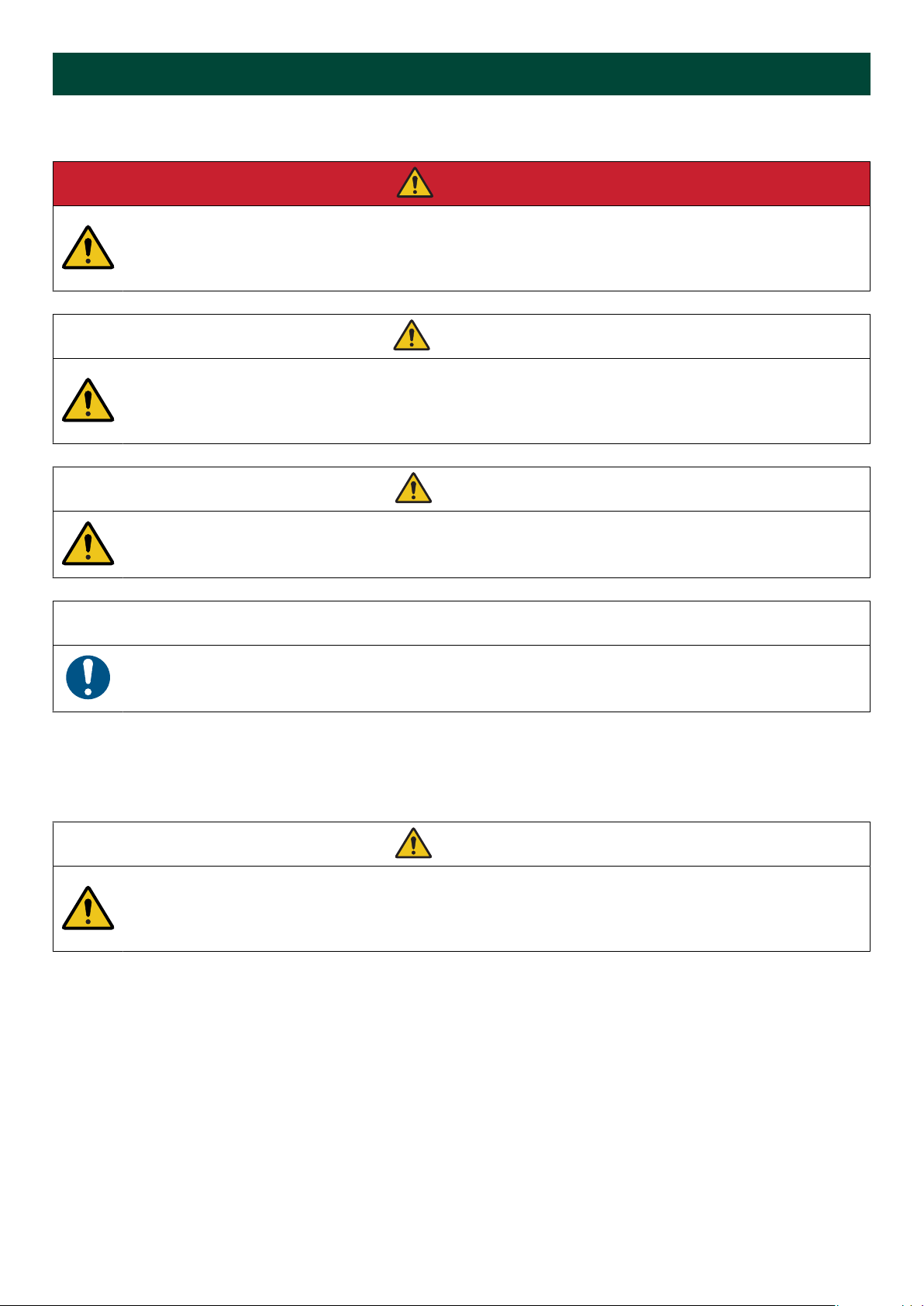
DANGER!
This shows dangerous situations.
If the guidelines are not followed, these situations will result in death, serious personal injury, and equipment
damage or destruction.
WARNING
This shows potentially dangerous situations.
If the guidelines are not followed, these situations could result in death, serious personal injury, and equipment
damage or destruction.
CAUTION
This shows low level risk situation.
If the guidelines are not followed, these situations could result in minor or moderate injury.
NOTICE
This shows an important notice
Make sure to read this information.
1.2 About the operator's manual
This document gives the necessary information to operate the controller.
CAUTION
Installation errors
Read this document before working with the controller. Failure to do this may result in human injury or damage
to the equipment.
Intended users of the operator's manual
The operator's manual is for the operator that uses the controller regularly.
The manual describes the LEDs, buttons and screens on the controller, alarm handling, and the logs menu.
OPERATOR'S MANUAL 4189341347A EN Page 3 of 32
1.3 Warnings and safety
Factory settings
The controller is delivered pre-programmed from the factory with a set of default settings. These settings are based on
typical values and may not be correct for your system. You must therefore check all parameters before using the controller.
Data security
To minimise the risk of data security breaches:
• As far as possible, avoid exposing controllers and controller networks to public networks and the Internet.
• Use additional security layers like a VPN for remote access, and install firewall mechanisms.
• Restrict access to authorised persons.
1.4 Legal information
Third party equipment
DEIF takes no responsibility for the installation or operation of any third party equipment, including the genset. Contact the
genset company if you have any doubt about how to install or operate the genset.
Warranty
NOTICE
Warranty
The controller is not to be opened by unauthorised personnel. If opened anyway, the warranty will be lost.
Disclaimer
DEIF A/S reserves the right to change any of the contents of this document without prior notice.
The English version of this document always contains the most recent and up-to-date information about the product. DEIF
does not take responsibility for the accuracy of translations, and translations might not be updated at the same time as the
English document. If there is a discrepancy, the English version prevails.
Copyright
© Copyright DEIF A/S. All rights reserved.
Software version
This document is based on the AGC 150 software version 1.15.0.
OPERATOR'S MANUAL 4189341347A EN Page 4 of 32
2. About ASC 150 Solar
2.1 About controller operation
The ASC 150 Solar controller controls and protects a photovoltaic system with up to 32 inverters. You can add the
controller to an existing plant as a single controller setup, or use it with other DEIF controllers in a power/energy
management system.
You can easily control the system from the display. The display can show your configured application with a simple diagram
that gives you information about the power sources and breaker feedback.
2.2 Typical application examples
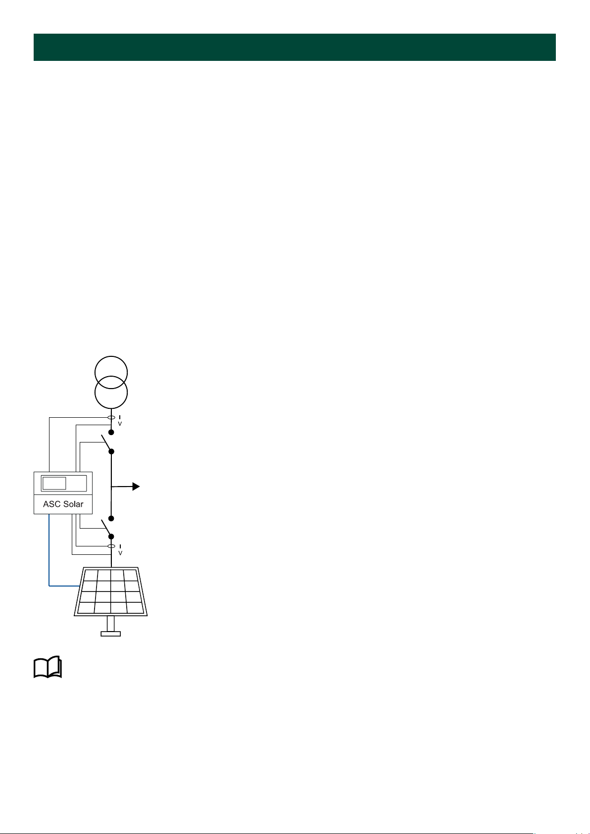
2.2.1 Single controller (without power management)
In single-controller applications, one ASC 150 Solar controller can control one photovoltaic system one photovoltaic
breaker and one mains breaker.
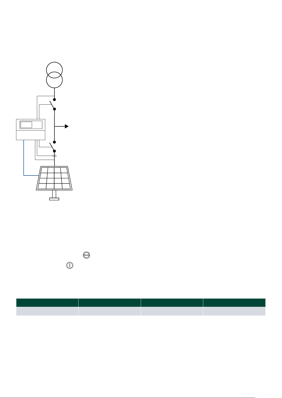
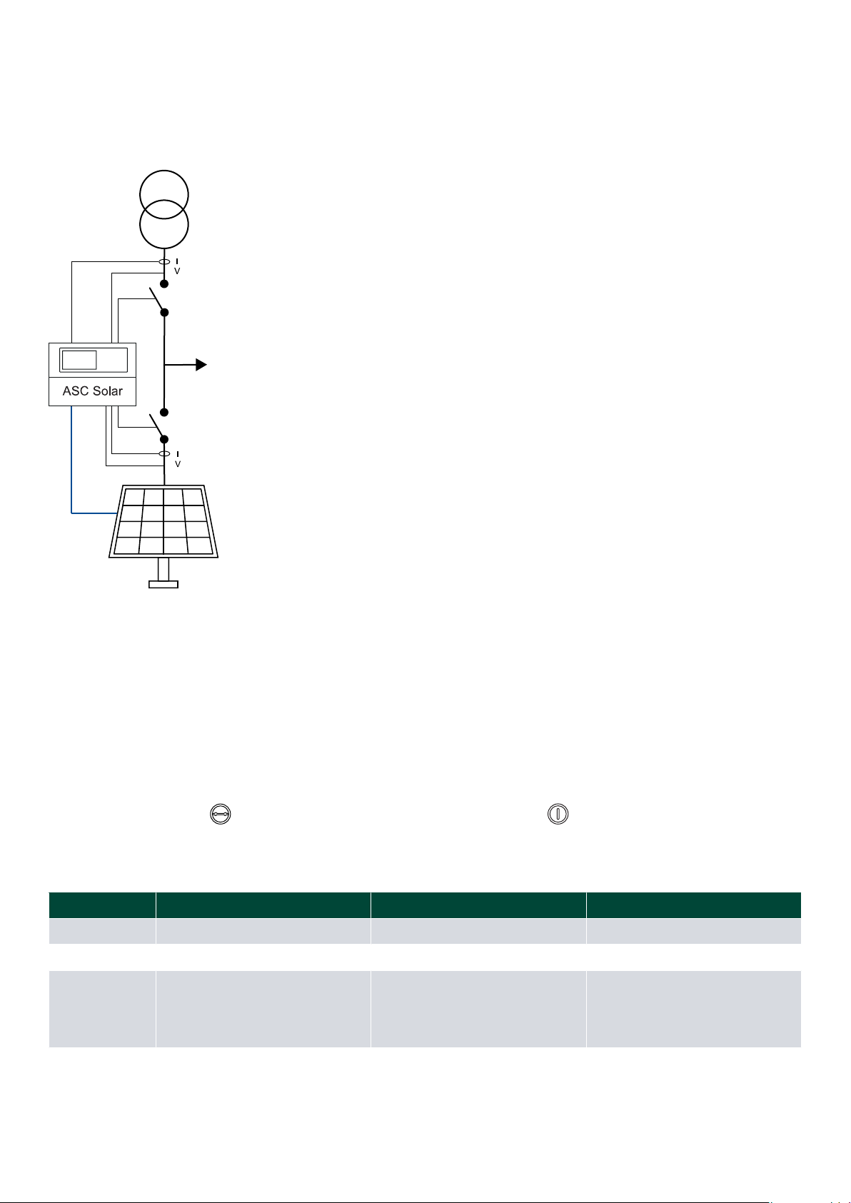
Application for one ASC 150 Solar controller
This example shows one ASC 150 Solar controller in a mains power export application. The ASC controls the PVS, the PVB,
and the mains breaker. The ASC controller gets power measurements and breaker positions from the mains.
More information
See Single-controller applications in the ASC 150 Solar Designer's handbook for variations on this controller
arrangement.
2.2.2 With power management
The ASC 150 Solar controller also works in DEIF power management applications, where the controller communicates with
other DEIF controllers. The ASC 150 Solar controller can control the PV system and the PV breaker in these
applications.
OPERATOR'S MANUAL 4189341347A EN Page 5 of 32

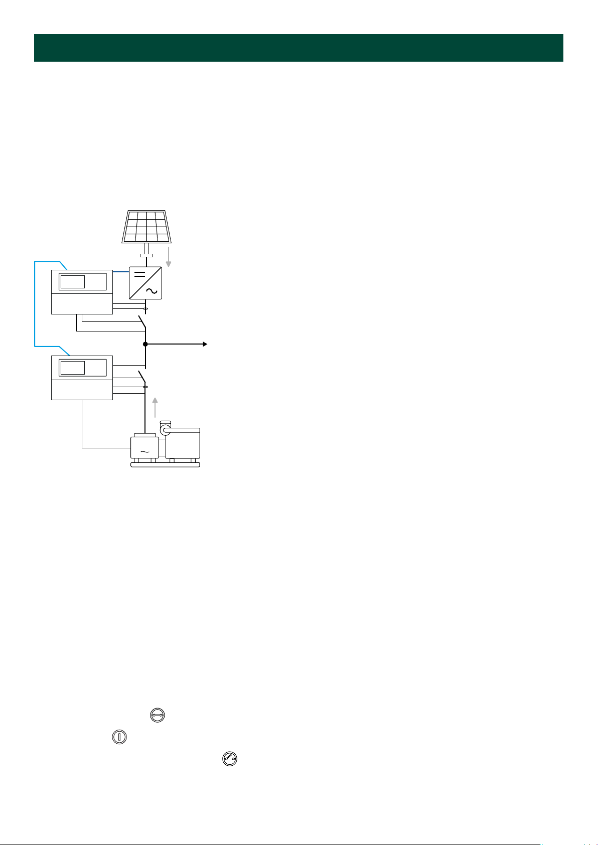
Application for an ASC controller in a power management system with AGC Genset and ASC Storage
This is an example of an off-grid application, where the controllers are in a power management system together. The ASC
150 Solar controller controls the PVS and the PV breaker.
G
Consumers
PMS
V
V
I
V
V
I
V
I
V
AGC Genset ASC Storage
ASC Solar
Application for an ASC 150 Solar in a power management system with AGC Mains, AGC Genset and ASC
Storage
This is an example of a grid-tied application. The ASC Solar is in a power management system with an AGC Mains, an AGC
Genset, and an ASC Storage.
G
PMS
Consumers
PMS
V
V
I
V
I
V
V
I
V
I
V
V
ASC Solar
ASC StorageAGC Genset
AGC Mains
OPERATOR'S MANUAL 4189341347A EN Page 6 of 32
More information
See the ASC 150 Solar data sheet for the variations on the grid-tied and off-grid arrangement.
You can select the plant mode for the AGC Mains controller when you have a power management system.
ASC Solar configuration
Basic settings > Application type > Type
Parameter Name Setting
6071 Operation mode Power management
AGC Mains configuration
Basic settings > Application type > Plant type > Plant mode
Parameter Name Setting
6070 Plant mode Select a plant mode (in the AGC mains
controller). For example, Mains Power Export.
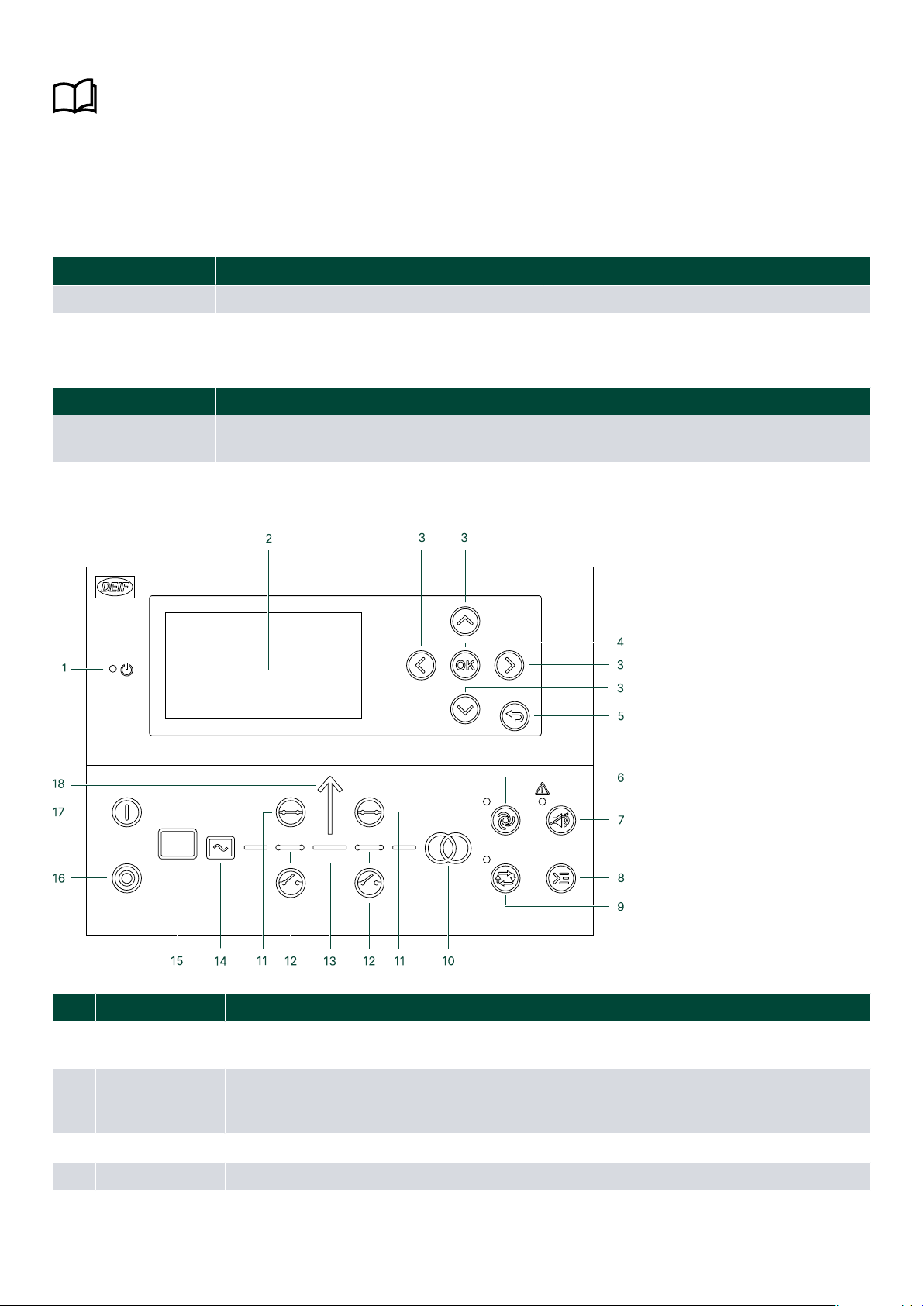
2.3 Display, buttons and LEDs
No. Name Function
1 Power Green: The controller power is ON.
The controller power is OFF.
2 Display screen*
Resolution: 240 x 128 px.
Viewing area: 88.50 x 51.40 mm.
Six lines, each with 25 characters.
3 Navigation Move the selector up, down, left and right on the screen.
4 OK Enter the Menu system.
OPERATOR'S MANUAL 4189341347A EN Page 7 of 32

No. Name Function
Confirm the selection on the screen.
5 Back Go to the previous page.
6 AUTO mode The controller automatically starts and stops (and connects and disconnects) the PV, and
automatically controls the power. No operator actions are needed.
7 Silence horn Turns off an alarm horn (if configured) and enters the Alarm menu.
8 Shortcut menu Access the Jump menu, General Shortcuts, Mode selection, and Lamp test.
9
mode
The operator or an external signal can also open and close the PV breaker. Automatic controller
actions are not possible.
The controller automatically synchronises before closing a breaker, and automatically de-loads
before opening a breaker.
10 Mains symbol
Green: Mains/busbar voltage and frequency are OK. The controller can synchronise and close
the breaker.
Red: Mains/busbar voltage failure.
11 Close breaker Push to close the breaker.
12 Open breaker Push to open the breaker.
13 Breaker symbols
Green: Breaker is closed.
Green flashing: Synchronising or de-loading.
Red: Breaker failure.
14 Inverter
Green: Inverter voltage and frequency are OK. The controller can synchronise and close the
breaker.
Green flashing: The inverter voltage and frequency are OK, but the V&Hz OK timer is still
running. The controller cannot close the breaker.
Red: The inverter voltage is too low to measure.
15 Photovoltaic
Green: There is solar PV system available feedback.
Green flashing: The solar PV system is getting ready.
Red: The solar PV system is not running, or there is no availability feedback.
16 Stop Stops the PV if is selected.
17 Start Starts the PV if is selected.
18 Load symbol
Power management application
Green: The supply voltage and frequency are OK.
Red: Supply voltage/frequency failure.
NOTE * You can use the display to monitor PV operation.
OPERATOR'S MANUAL 4189341347A EN Page 8 of 32

3. Operating the system
3.1 Mimic function
Settings > Basic settings > Controller settings > Display > LED mimic
Parameter no. Item Range
6082 LED mimic Standard
Guided
Standard
The control buttons and LEDs are shown.
If you the stop the photovoltaic system the PVS symbols are
shown in red.
Guided
Active control buttons, LEDs, and the PVS symbols are shown,
inactive are not shown.
Example: The controller is in mode, and the PVS is not
operating. The only possible action is to start the PVS, or open the
mains breaker. Therefore, only the start button, the red PVS
symbols, and the button to open the mains breaker are shown.
All Mimic settings
The breaker symbol is shown in red:
• Breaker position failure
• Breaker close failure
The breaker symbol flashes green:
• The controller is synchronising
• The controller is de-loading
3.2 Running modes
The controller has two running modes:
•AUTO : The controller operates automatically and the operator cannot start sequences manually.
•SEMI-AUTO : The operator must start all sequences. You can do this with the buttons, Modbus commands, or digital
inputs.
SEMI-AUTO mode
Use external signals to operate the controller in mode.
Give an external signal with:
1. Buttons on the display
2. Digital inputs*
OPERATOR'S MANUAL 4189341347A EN Page 9 of 32

3. Modbus commands
NOTE * The controller has a limited number of digital inputs. See Digital inputs in the ASC 150 Solar Designer's
handbook for availability.
Commands in SEMI-AUTO mode
Command Description
Start The start sequence for the photovoltaic system is started. The breaker must be
closed before you can start the system.
Stop The PVS is stopped.
Close the PV breaker The controller closes the PV breaker if there is voltage on the busbar.
Open the PV breaker The controller ramps down and opens the PV breaker at the breaker open point.
Close the mains breaker
In applications with a PV system, a mains, and external gensets, it is only possible to
close the mains breaker if:
• The genset breaker(s) is open
• The PV breaker is closed.
The PV breaker must be closed to make sure there is no voltage on the busbar before
you close the mains breaker.
Open the mains breaker The controller opens the mains breaker instantly.
3.3 Display settings
To adjust for ambient lighting, configure the display settings.
Settings > Basic settings > Controller settings > Display > Display control
Parameter Text Range Default
9151 Backlight dimmer 0 to 15 * 12
9152 Green LEDs dimmer 1 to 15 * 15
9153 Red LEDs dimmer 1 to 15 * 15
9154 Contrast level to 0
9155 Sleep mode timer 1 to 1800 s 60 s
9156 Enable mode timer) OFF
ON ON
9157 Alarm Jump OFF
ON ON
9158 Engineering units Bar/Celcius
PSI/Fahrenheit Bar/Celcius
NOTE * Low numbers are minimum brightness and high numbers are maximum brightness.
3.4 Easy connect
You can use Easy connect in your energy management system if the application consists of only genset or ASC Solar
controllers. Easy connect is a fast and easy way to add more controllers to a new or existing application. Easy connect
commands normally come from the display, but they can also be sent from and Modbus.
More information
See Easy connect in the ASC 150 Solar Designer's handbook for how to activate and use Easy connect.
OPERATOR'S MANUAL 4189341347A EN Page 10 of 32
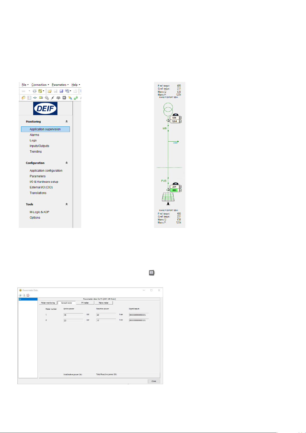
3.5 Utility software
3.5.1 Application supervision
Use the application supervision function in the utility software to see the plant operation. This includes how much power
each power source is producing.
You can find Application supervision in the vertical menu in the utility software.
3.5.2 Data monitoring and counters
Power meter monitoring
Go to Application supervision and select Power meter Data to open the Power meter Data window.
OPERATOR'S MANUAL 4189341347A EN Page 11 of 32

Electrical data monitoring
Go to Application supervision and select Electrical Data to open the Electrical Data window.
Inverter data
Go to Application supervision and select Inverter data to open the Inverter data window. You can monitor the weather
data and performance data as well as individual or shared PV inverter data.
USW counters
You can view and adjust a number of counters using the USW. Click on the Counters icon in the upper horizontal menu
to open the counters window.
More information
See General functions in the ASC 150 Solar Designer's handbook for more information about the functions in the
utility software.
OPERATOR'S MANUAL 4189341347A EN Page 12 of 32

3.5.3 Trending
Use the trending function in the utility software to see real-time operation. Trending is possible when a PC is connected to
the controller and the trending window is open. It is not possible for the controller to save the data.
How to configure trending
1. Click on Trending in the vertical menu on the left to see the trending page.
2. Click on Edit the trending tags .
3. In the pop-up window, select the data you want to trend.
4. Click OK to confirm your selection.
5. Click on the Save a views file button if you want to save the trending data to a .trend file.
6. The trending begins automatically when you have selected the data to trend.
7. You can see the trending data at the bottom of the page. The numerical values are also shown here.
8. Click on the pause button to pause the update of the trending window. The trending continues in the background.
9. When the trending is paused, you can use the zoom buttons and the scroll buttons to navigate the
trending graph.
OPERATOR'S MANUAL 4189341347A EN Page 13 of 32
4. Modes of operation
Operate the ASC Solar controller in AUTO mode or mode. In AUTO mode, the controller automatically starts
and stops the PV, and controls the power automatically. In mode, the operator or an external signal can open
and close the PV breaker, and start the system.
4.1 Island operation
The PV system is non-grid forming. The system can supply the load in island mode if there is a grid-forming source in
the application, for example, a genset. Use the ASC Solar controller to maintain a minimum genset load and support the
generator with reactive load when needed.
G
Consumers
PMS
V
I
V
V
I
V
AGC Genset
ASC Solar
AUTO mode
1. Select AUTO mode.
2. The PV breaker closes automatically when the voltage and frequency are OK.
3. Activate a start signal for the
• Use a digital input or
• Use a time-dependent start command.
4. The PV system starts.
5. When the PVS is ready, the grid-forming source ramps down to the minimum load. The PVS supplies the remaining load.
6. If the PVS cannot supply the load, the genset supplies the extra load.
7. To stop the PVS, activate a stop signal.
• Use a digital input or
• Use a time-dependent stop command.
8. The PVS stops.
SEMI-AUTO mode
1. Push the Close breaker button to close the PV breaker.
2. Push the Start button on the controller to start the PVS.
3. To stop the PVS, push the Open breaker button to open the breaker and stop the PVS.
OPERATOR'S MANUAL 4189341347A EN Page 14 of 32
4.2 Fixed power
In AUTO and mode, the PV system supplies the amount of power configured in the set point for fixed
power.
The controller does not need power measurements from other power sources in fixed power applications.
V
I
V
ASC Solar
Start sequence
1. Activate a start signal.
• AUTO mode:
◦ The PV breaker closes automatically when you select AUTO mode, and the voltage and frequency are OK.
◦ Activate a start signal with digital or time-dependent inputs.
• mode:
◦ Push the Close breaker button to close the PV breaker.
◦ Push the Start button on the controller.
2. The PVS supplies the load configured in the set point for PV fixed power (parameter
3. If the load increases to more than the set point, the mains supplies the extra load.
Settings > Power set points > Fixed Power > Set point
Parameter Text Range Default
7051 Set point to 2000 kW 500 kW
OPERATOR'S MANUAL 4189341347A EN Page 15 of 32

4.3 Mains power export
In this mode a constant level of power through the mains breaker is maintained. The power can be exported to the mains or
imported from the mains, but always at a constant level. The set point can be 0 kW for zero export applications.
Start sequence
1. Activate a start signal for the PV.
• AUTO mode:
◦ The PV breaker closes automatically when you select AUTO mode, and the voltage and frequency are OK.
◦ Activate a start signal with digital or time-dependent inputs.
• mode:
◦Push the Close breaker button to close the PV breaker.
◦ Push the Start button on the controller.
2. The PVS ramps up to reach the MPE kW set point (parameters 7001 and
3. If the PVS cannot supply this load, the mains supplies the remaining load.
Settings > Power set point > Mains power export and peak shaving > Day/night power set
point
Parameter Text Range Default
7001 Mains power, Day to 20000 kW 750 kW
7002 Mains power, Night to 20000kW 1000 kW
7006 MPE/PS scale
OPERATOR'S MANUAL 4189341347A EN Page 16 of 32

Settings > Power set point > Mains power export and peak shaving > Day/night settings
Parameter Text Range Default
7011 Daytime period, start hour 0 to 23 8
7012 Daytime period, start min. 0 to 59 0
7013 Daytime period, stop hour 0 to 23 16
7014 Daytime period, stop min. 0 to 59 0
OPERATOR'S MANUAL 4189341347A EN Page 17 of 32
4.4 Peak shaving
The PV system supplies the extra load when the mains import increases to more than the maximum import set point.
The system runs parallel to the mains.
AUTO mode
1. Select AUTO mode.
2. The PV breaker closes automatically.
3. Activate a start signal.
• Use a digital input or
• Use a time-dependent start command.
4. The PVS supplies the extra load when the mains import is more than the maximum set point for mains import.
SEMI-AUTO mode
1. Push the Close breaker button to close the PV breaker, then push the Start button on the controller.
2. When the PVS is parallel to the mains, the PVS is controlled by the peak shaving set point.
Settings > Power set point > MPE/Peak shaving > Day/night power set point
Parameter Text Range Default
7001 Mains power, Day to 20000 kW 750 kW
7002 Mains power, Night to 20000kW 1000 kW
7006 MPE/PS scale
OPERATOR'S MANUAL 4189341347A EN Page 18 of 32

Settings > Power set point > MPE/peak shaving > Day/night settings
Parameter Text Range Default
7011 Daytime period, start hour 0 to 23 8
7012 Daytime period, start min. 0 to 59 0
7013 Daytime period, stop hour 0 to 23 16
7014 Daytime period, stop min. 0 to 59 0
OPERATOR'S MANUAL 4189341347A EN Page 19 of 32
5. Menus
5.1 Menu structure
The controller has two menu systems, which can be used without password entry:
•The View menu system: Shows the operating status and values. The system has 20 configurable windows, that can be
entered with the arrow buttons.
•The Settings menu system: The operator can see the controller's parameters. A password is necessary to change the
parameter settings.
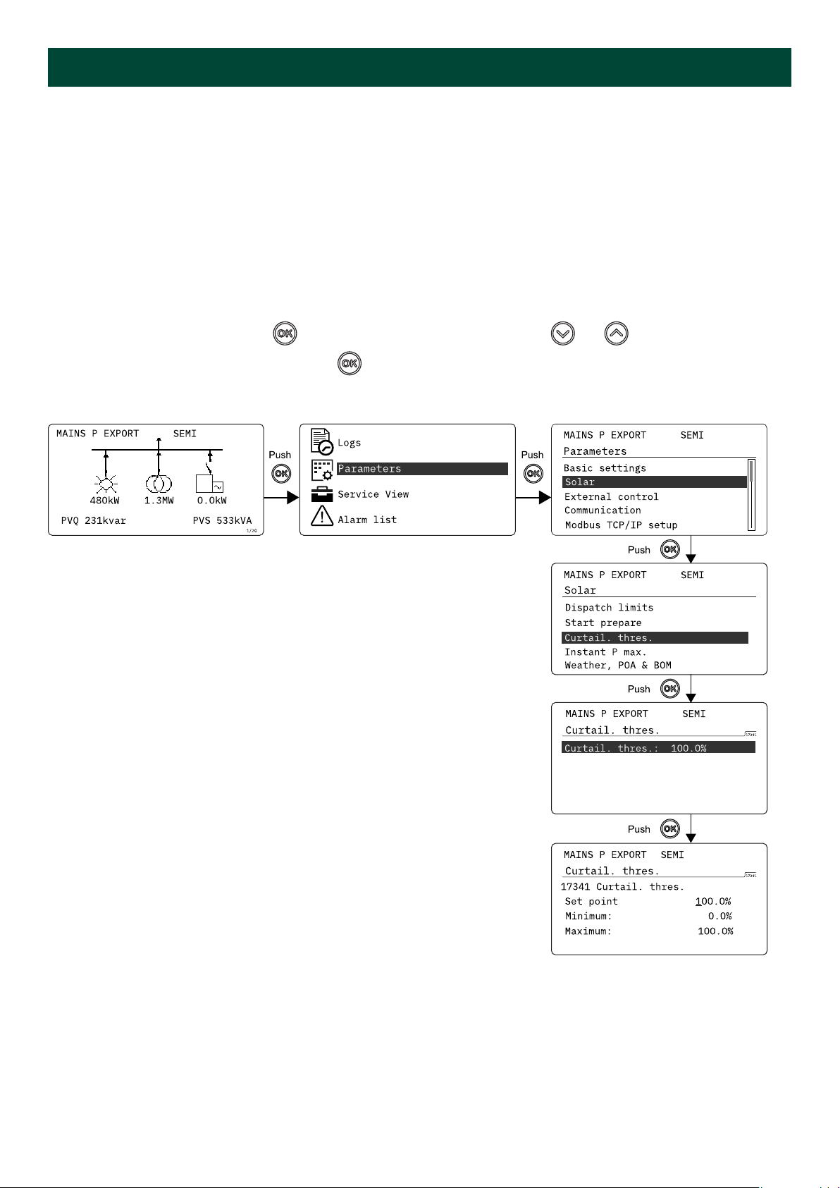
5.2 Settings menu
You can configure the controller in the settings menu and you can also find information, which is not available in the view
menu. From the view menu, push the button to find the settings menu. Use the and buttons to find the
different settings parameter and select with the button.
Settings menu example
OPERATOR'S MANUAL 4189341347A EN Page 20 of 32
Table of contents


