SteamSpa S 450 User manual
STEAM BATH GENERATOR USER GUIDE
4.5KW
6KW
7.5KW
9KW
10.5KW
12KW
MODELS
BLACK SERIES
V2.1
W
H
I
S
P
E
R
Q
U
I
E
T
B
U
I
L
T
-
I
N
A
U
T
O
D
R
A
I
N
C
O
N
T
I
N
U
O
U
S
S
T
E
A
M
Q
U
I
C
K
S
T
A
R
T

SteamSpa PHONE: 800-856-0172 FAX: 866-560-1060 http://steamspa.com [email protected]
Page 3
INSTALLATION & USER GUIDE
TABLE OF CONTENTS
PROLOGUE....................................................................................................................... 4
USER INSTRUCTIONS ......................................................................................................... 4
CHOOSING THE RIGHT LOCATION .......................................................................................... 4
INSTALLATION DRAWING OF STEAM GENERATOR ..................................................................... 5
PLUMBING INSTALLATION ................................................................................................... 8
STEAM GENERATOR SPECIFICATIONS................................................................................... 10
ELECTRICAL REQUIREMENTS ............................................................................................. 11
ASSEMBLY GRAPH FOR POWER WIRE .................................................................................. 12
INSTALLATION OF THE TOP LIGHT........................................................................................ 14
STEAM GENERATOR DISSECTION DIAGRAM........................................................................... 15
CARE & USE FOR THE CONTROL PANEL ................................................................................ 16
CONTROLLER BOX CONTENT .............................................................................................. 16
CONTROL PANEL INSTALLATION INSTRUCTIONS ..................................................................... 17
TESTING THE MACHINE ..................................................................................................... 18
CONTROL PANEL DIAGRAM................................................................................................ 18
CONTROL PANEL OPERATION ............................................................................................. 19
STEAM GENERATOR MAINTENANCE ..................................................................................... 25
TECHNICAL PARAMETERS.................................................................................................. 29
WIRING DIAGRAMS.......................................................................................................... 30
IMPORTANT!
PRIOR TO INSTALLATION, LET WATER RUN THROUGH THE WATER PIPE TO CLEAN ANY POSSIBLE
DEBRIS BEFORE CONNECTING THE GENERATOR.

SteamSpa PHONE: 800-856-0172 FAX: 866-560-1060 http://steamspa.com [email protected]
Page 4
INSTALLATION & USER GUIDE
PROLOGUE
Thank You for choosing SteamSpa for health, beauty and relaxation. Now you can enjoy your own private sanctuary in the comfort
of your own home. Let your stress melt away as you relax in your state of the art Steam Room.
For Centuries people have recognized the health benefits of saunas. Leave your stress behind and enter a world of total relaxation,
ridding you of pain, toxins, and sore muscles as well as increasing your blood circulation etc., leaving your skin glowing. Besides
these physical effects, a SteamSpa Session will leave you totally relaxed by providing you a peaceful and relaxing environment
away from all.
Our advanced technology, engineering, and product development provides Steam Generators that enhance the lifestyles of people
throughout the world. SteamSpa is continuously refining, updating and developing their products assuring the optimum quality
and performance of their products. Working with the industries top engineers we have developed the most efficient, dependable
and highest quality products.
USER INSTRUCTIONS
1. Check for visible damages upon delivery of Generator. Any damages to packaging should be reported immediately to shipping
company delivery representative and SteamSpa’s Customer Service Dept.
2. Check model and accessories are correct, including voltage input. Any discrepancies are to be reported to SteamSpa’s
Customer Service Dept. within 48 hours of delivery.
3. Read installation instructions in detail for a secure and effective installation of SteamSpa generators.
4. SteamSpa recommends the use of a licensed plumber and electrician for proper installation of SteamSpa generators.
5. SteamSpa shall not be responsible for product damage or malfunction caused by self-installation or installation procedures
which do not comply with user manual.
6. SteamSpa generators should be installed indoors only.
CHOOSING THE RIGHT LOCATION
1. The generator should be less than 25ft from the steam room for best performance.
2. The steam generator should not be installed in the steam room
3. Do not install outdoor or in any places that will influence the performance of the machine by the environment.
4. Do not install in a frigid location or any places where the water will freeze.
5. Do not install near flammable chemicals.
6. Install in a dry place where the ventilation is good.
7. Install an exhaust fan outside of the steam room for the excess steam to be expelled from the shower room.
8. The steam generator has a hanging groove for wall installations..
9. Both sides and the top of the steam generator need to reserve at least 12 inches space.
10. The area where the machine is installed must be easily cleaned up and convenient for the disassembly of the machine.
11. The installation area must be convenient for the steam generator draining system.
12. The steam tube, safety valve, drain valve, water tube and steam outlet remain very heated after the steam generator has
stopped working for some time.
13. The controller panel should be installed away from the steam head to avoid false readings,please read the instructions for the
controller’s installation and operation.

SteamSpa PHONE: 800-856-0172 FAX: 866-560-1060 http://steamspa.com [email protected]
Page 5
INSTALLATION & USER GUIDE
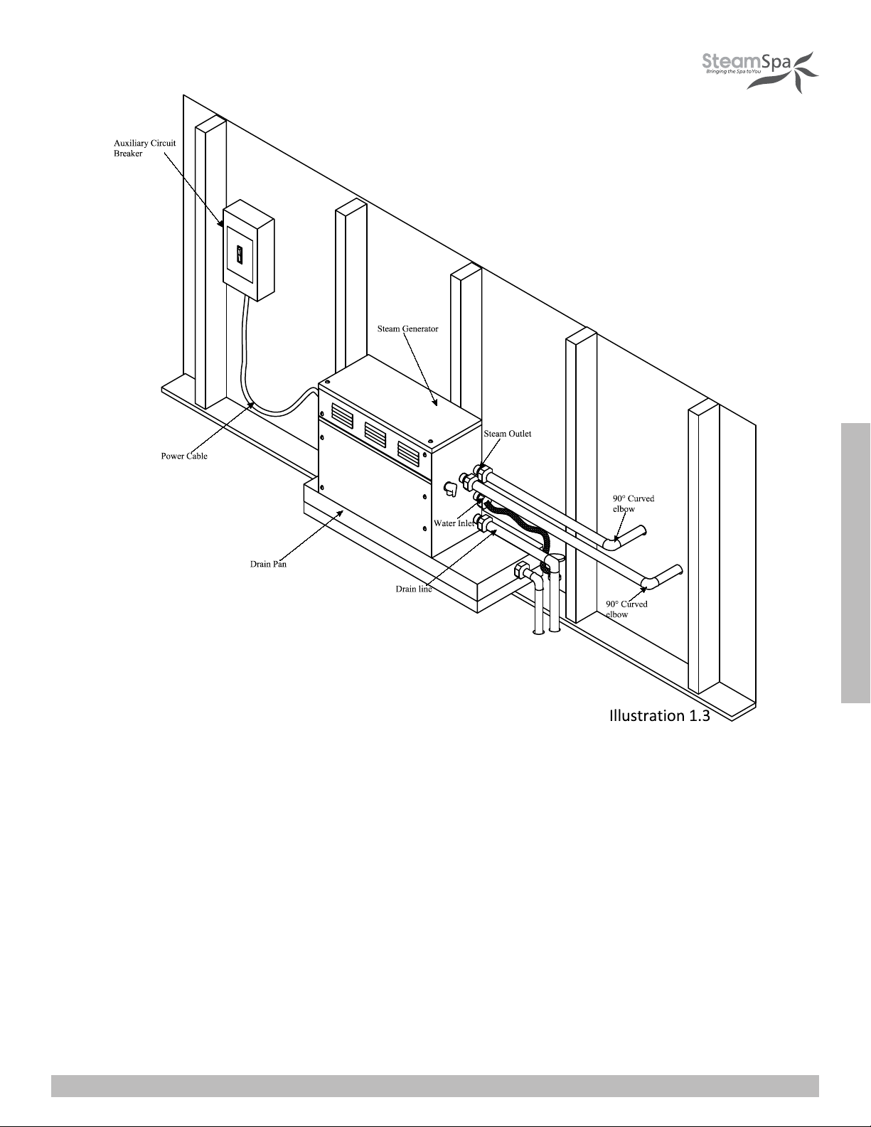
INSTALLATION DRAWING OF STEAM GENERATOR
ATTENTION! The drawing is only for explanation purposes. As for practical design of steam room, please consult with a qualified
designer, architect or builder.
SteamSpa PHONE: 800-856-0172 FAX: 866-560-1060 http://steamspa.com [email protected]
Page 6
INSTALLATION & USER GUIDE
ATTENTION! The drawing is only for explanation purposes, please consult with a qualified designer, architect or builder.
IMPORTANT! All pipe connections should have unions and adapters for easy disconnect.

SteamSpa PHONE: 800-856-0172 FAX: 866-560-1060 http://steamspa.com [email protected]
Page 7
INSTALLATION & USER GUIDE
ATTENTION! The illustration is just an example; the practical installation must comply with the nation’s electrical criteria, and be
done by a professional electrician.
The steam generator maybe installed in these location.
1. In closet located behind the shower.
2. In Attic
3. In basement etc.
ATTENTION! If the installation of the steam generator will be more then 10 to 15 feet away from the steam room. It is
recommended to increase the size of the generator 1 or 2 kilowatts higher to increase the steam flow.
110

SteamSpa PHONE: 800-856-0172 FAX: 866-560-1060 http://steamspa.com [email protected]
Page 8
INSTALLATION & USER GUIDE
PLUMBING INSTALLATION
WARNING! The installation of all water supply lines should be in accordance to all national and local codes by a licensed plumber.
1. Use unions when connecting pipes.
2. Use brass pipes or copper pipe only.
3. Do not use black and galvanized or PVC pipes.
WATER SUPPLY PIPE (1/2’’)
1. Connect hot water or cold water pipes. However it should not exceed 160F.
2. Install a shut off valve in the water supply line.The shut off valve should be installed in a place where it is easily accessible in
case of an emergency.
3. Flush the water supply line completely before connecting the water pipe to the steam generator, to remove any sediments in
the water.
4. Use a 3/8” steel braded flex hose with a shut off valve to connect the main waterline to the generator. See page 5 illustration
1.2.
5. The shut off valve should be open approximately 25% to reduce water pressure to the generator. The water pressure to the
generator should be between 15 to 20 PSIG if necessary, decrease the pressure accordingly.
6. It is highly recommended to install a pressure reducing valve to reduce the water pressure between 15 to 20 PSI.
STEAM PIPE (3/4’’)
1. Do not install any stop valves in the steam pipes. The steam can never be obstructed.
2. Install a ¾” copper pipe between the steam generator and the steam nozzle for all generators, except the 4.5KW which
requires a ½” copper pipe.
3. If needed, the heat insulation material used to insulate the steam pipe should be resistant to temperatures as high as 240F or
higher.
4. The shorter the distance, the better. Use curved elbows when connecting pipes to allow the steam to flow smoothly through
the steam pipe.
STEAM HEAD (3/4’’)
ATTENTION! Steam Head and the steam outlet gets very hot, try to avoid installing the steam head in a position which will easily
come into contact with the person bathing.
1. Install the steam head approximately 12 inches above the ground floor. If the steam room material is acrylic or non-heat-
resistant sheet, please consult with material manufacturer about steam room applications.
2. The steam head outlet should be installed face down. To prevent scalding bather with steam or water.
ATTENTION! Tighten steam head by hand. Do not use a spanner or other tools, use a little soap water and soft sponge to wipe,
and do not use erosive chemical solutions or crude cleaning tools.
IMPORTANT!
1. Please consult manufacturer of materials like acrylic, fiber glass or other anti-heat sheet about the installation of the steam
head.
2. In the entire steam room, it is required that steam does not leak out. The pipes, its accessories and the holes should be air
proof by applying sealant so that no steam will enter the holes in the wall.

SteamSpa PHONE: 800-856-0172 FAX: 866-560-1060 http://steamspa.com [email protected]
Page 9
INSTALLATION & USER GUIDE
DRAINPIPE (1/2’’)
ACCORDING TO THE NATIONAL AND LOCAL PLUMBING CODES: The steam generator drain valve should be equipped with
a drainpipe. The steam generator drains the water by gravity.Check local code requirements for drain valves. Do not connect the
safety valve or steam line to drain line.
SAFETY VALVE (3/4’’)
1. Safety valve is an automatic system that is actuated by pressure in order to prevent steam pressure increasing in the interior
of the generator .
2. The pressure limit range of the safety valve is 15 PSIG and the pressure will begin to decrease if pressure should come over
this value.
3. If it is allowed by local codes, provide the safety valve with exterior drainpipe.
4. Do not dismantle the pressure relief valve while generator is in operation..
5. To maintain the proper automatic operation of the safety valve, make sure the safety valve connection pipe is smooth.

SteamSpa PHONE: 800-856-0172 FAX: 866-560-1060 http://steamspa.com [email protected]
Page 10
INSTALLATION & USER GUIDE
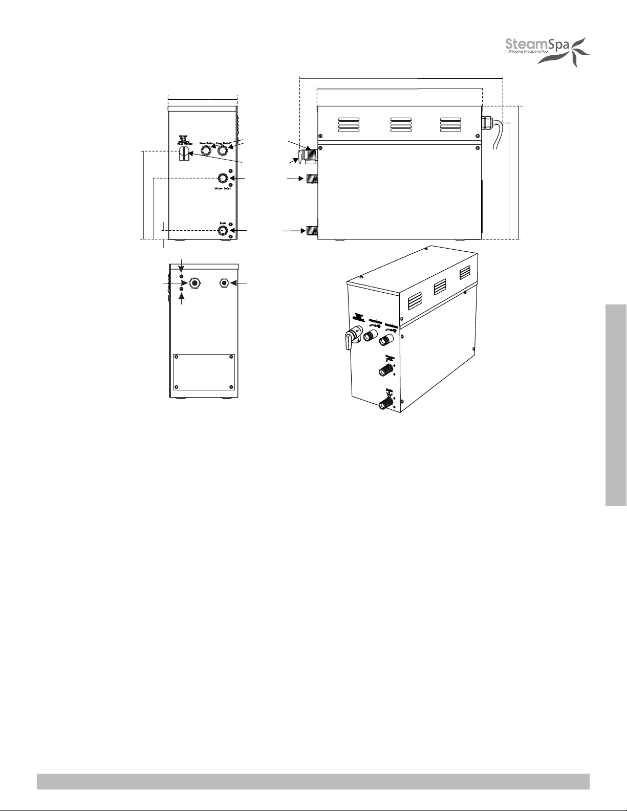
STEAM GENERATOR SPECIFICATIONS
4.5kW
6kW/7.5kW/9kW
Safety valve
Steam out let
Wat er inl et
Wat er
drainage
206mm
188mm
151mm
32mm
43mm
142mm
266 mm
302mm
395mm
Fuse for wire power supply
Power wire hol e C o n tr o l le r w i r e
and l i ght wire hole
304mm
400mm
160m m
100m m
30mm
30mm
180mm
260m m
370mm
Steam outlet
S a f e t y
valve
Water inlet
Water drainage
Fus e for w ire pow er s upply
Pow er wire hole
C o n tro ller wire
an d lig h t wir e
hole
Fuse for wire
power supply
Fuse for wire
power supply
62mm
72mm
SteamSpa PHONE: 800-856-0172 FAX: 866-560-1060 http://steamspa.com [email protected]
Page 11
INSTALLATION & USER GUIDE
ATTENTION! To facilitate maintenance, keep the steam engine clean. If the information provided is limited, do not operate on the
pipeline and electric equipment arbitrarily as shown in the figure for proportion.
ELECTRICAL REQUIREMENTS
ELECTRICAL SUPPLY CIRCUITRY
1. Test the voltage of the power supply and make sure suitable voltage is used for the steam generator.
2. Insulated copper wire should be used with an anti-heat temperature of 90 C and a specified voltage of 300V. Refer to national
or local electricity consumption code for the specifications. Refer to the ammeter for the ampere.
3. Connect suitably sized equipment grounding wire into the ground terminal.
4. All the connections must be in accordance with national and local electricity consumption codes and be installed by
professional electricians.
10.5kW/12kW/15kW
535mm
435mm
Steam outlet
Safety valve
Water inlet
Water
drainage
Fuse for wire power supply
Power wire hole Controller wire and
light wire hole
35 0mm
38 5mm
234mm
273mm
183mm
34mm
Fuse for wire
power supply

SteamSpa PHONE: 800-856-0172 FAX: 866-560-1060 http://steamspa.com [email protected]
Page 12
INSTALLATION & USER GUIDE
The data provided above is for 240V single-phased motors. Install an independent circuit breaker between supply line and steam
generator. Install a power disconnect within sight of steam generator to cut-off power when not in use.
ASSEMBLY GRAPH FOR POWER WIRE
ATTENTION! To avoid damage to the equipment, do not connect electric current directly to heating elements.
WARNING! This graph is for explanation only. For actual installation, refer to national and local electricity consumption codes by
professional electricians.
Ampere Meter
Ty p e Power KW
S600
S750
6
7.5
9
240V
240V
240V
25
32
38
10
8
8
150
225
300
Ap p l i cab l e s p ace o f
the room (cu.Ft. *)
E l e c t r i c i t y
supply (1PH) E l e c t r i c
current (A)
Specifications for
power wire (AWG)
10.5 240V 44 6400
12 240V 50 6
450
S900
S1050
S1200
S450 4.5 240V 19 12
90
240V
( 2 4 0 V ~ 1PH)
Power con nectio n term inal
( 4 . 5 - 1 2kW )
L1
Ground Hot
L2
L1 L2
L2
L1
SteamSpa PHONE: 800-856-0172 FAX: 866-560-1060 http://steamspa.com [email protected]
Page 13
INSTALLATION & USER GUIDE
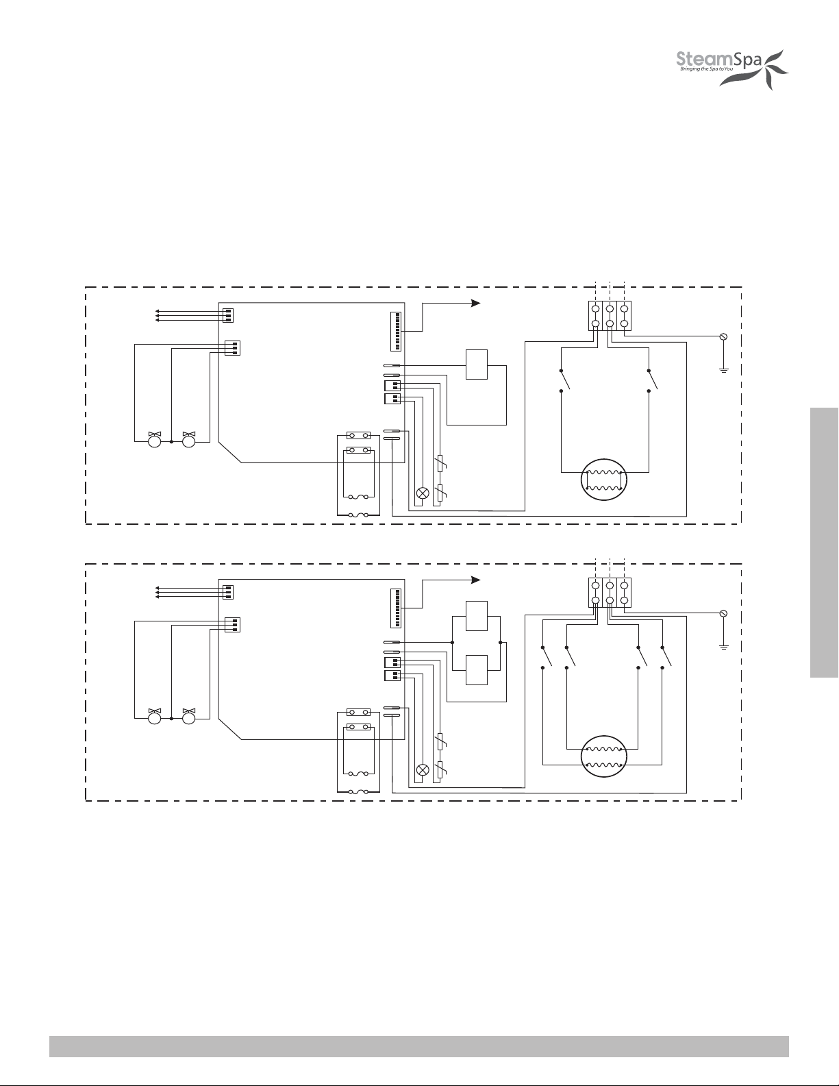
WIRING DIAGRAM
J1-1
J2-1
J2-2
J1-2
J1J2
S S
L1 G
S600
Su p p ly
Red
Black
R e d
B l a c k
Black
L2
Red
Red
T o C o nt r ol P a n e l
Fill water valve
Drain water valve
T e rm i n a l B l o c k
Ye l l ow / G r e e n
R e d
B l a c k
R e d
Black
White
B la c k
Yel low
R e d
B l a c k
Red
Red Red
Red
Wa te r L e ve l Se n sor
Red ( S h o r t P i n )
Bl ack ( L o n g P i n )
Yel l o w ( Mi d d l e P i n )
T o C o nt r ol P a n e l
Fill water valve
Drai n water valve
T e rm i n a l B l o c k
J1-1
J2-1
J3-1
J3-2
J2-2
J1-2
J1J2J3
S S
G
Ye l l ow / G r e e n
R e d
B l a c k
Red
Black
White
Black
Yellow
R e d
B l a c k
Red
Red Red
Red
Su p p ly
R e d
B l a c k
RedBlack
L1L2
Wa te r L e ve l Se n sor
Red ( S h o r t P i n )
Bl ack ( L o n g P i n )
Yel l o w ( Mi d d l e P i n )
Red
Red
Red
S750 S900
Red Red
Black
Black
Black
Black
Black
Blac k
Red
Black
J1-1
J1-2
J1
S S
L1 G
S450
Su p p ly
Red
R e d
B l a c k
Black
L2
Red
T o C o nt r ol P a n e l
Fill water valve
Drain water valve
T e rm i n a l B l o c k
Ye l l ow / G r e e n
R e d
B l a c k
R e d
Black
White
B la c k
Yellow
R e d
B l a c k
Red
Red Red
Red
Wa te r L e ve l Se n sor
Red ( S h o r t P i n )
Bl ack ( L o n g P i n )
Yel l o w ( Mi d d l e P i n )
Bla ck
SteamSpa PHONE: 800-856-0172 FAX: 866-560-1060 http://steamspa.com [email protected]
Page 14
INSTALLATION & USER GUIDE
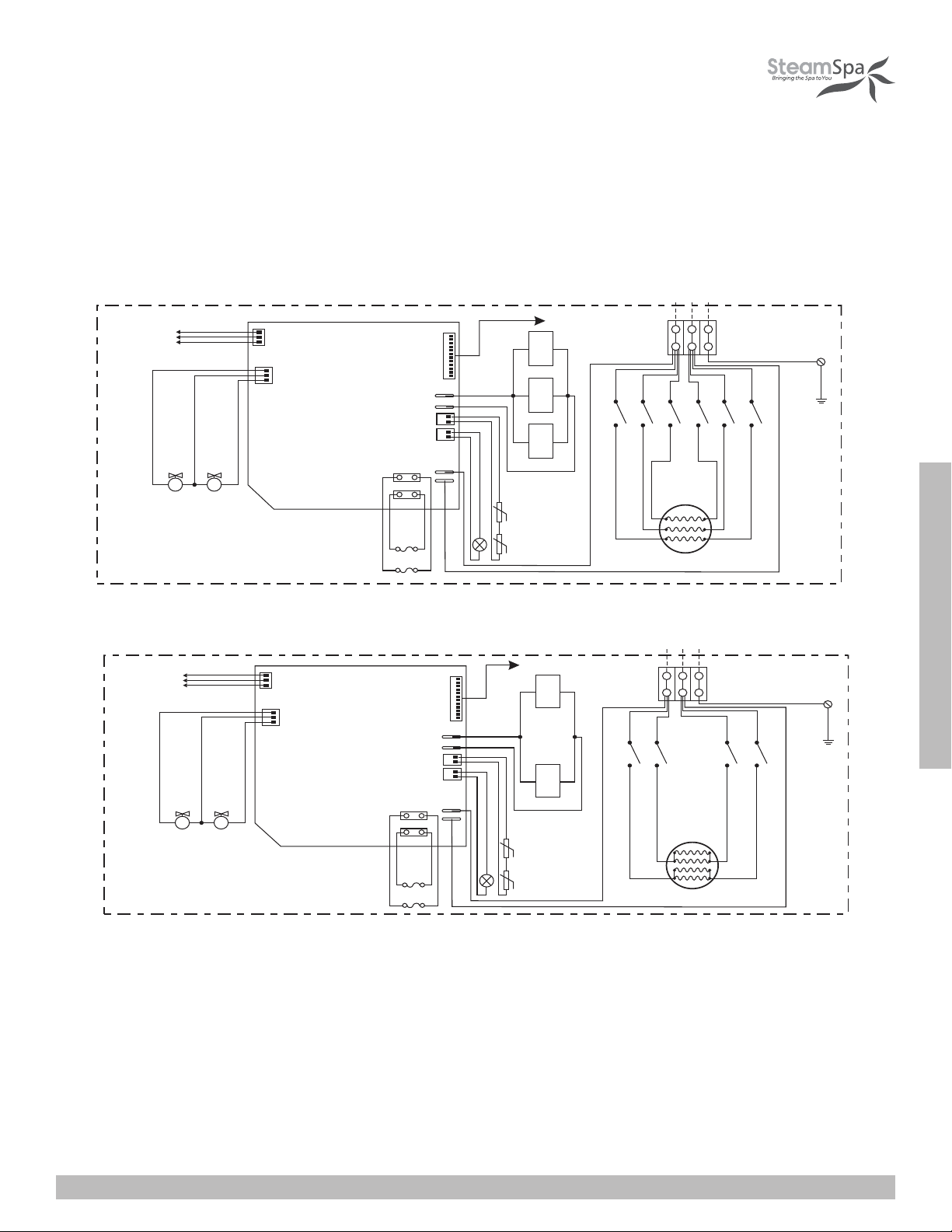
WIRING DIAGRAM
J1-1
J2-1
J2-2
J1-2
J1J2
S S
L1 G
S600
Su p p ly
Red
Black
R e d
B l a c k
Black
L2
Red
Red
T o C o nt r ol P a n e l
Fill water valve
Drain water valve
T e rm i n a l B l o c k
Ye l l ow / G r e e n
R e d
B l a c k
R e d
Black
White
B la c k
Yel low
R e d
B l a c k
Red
Red Red
Red
Wa te r L e ve l Se n sor
Red ( S h o r t P i n )
Bl ack ( L o n g P i n )
Yel l o w ( Mi d d l e P i n )
T o C o nt r ol P a n e l
Fill water valve
Drai n water valve
T e rm i n a l B l o c k
J1-1
J2-1
J3-1
J3-2
J2-2
J1-2
J1J2J3
S S
G
Ye l l ow / G r e e n
R e d
B l a c k
Red
Black
White
Black
Yellow
R e d
B l a c k
Red
Red Red
Red
Su p p ly
R e d
B l a c k
RedBlack
L1L2
Wa te r L e ve l Se n sor
Red ( S h o r t P i n )
Bl ack ( L o n g P i n )
Yel l o w ( Mi d d l e P i n )
Red
Red
Red
S750 S900
Red Red
Black
Black
Black
Black
Black
Blac k
Red
Black
J1-1
J1-2
J1
S S
L1 G
S450
Su p p ly
Red
R e d
B l a c k
Black
L2
Red
T o C o nt r ol P a n e l
Fill water valve
Drain water valve
T e rm i n a l B l o c k
Ye l l ow / G r e e n
R e d
B l a c k
R e d
Black
White
B la c k
Yellow
R e d
B l a c k
Red
Red Red
Red
Wa te r L e ve l Se n sor
Red ( S h o r t P i n )
Bl ack ( L o n g P i n )
Yel l o w ( Mi d d l e P i n )
Bla ck
T o C o nt r ol P a n e l
Fill water valve
Drain water valve
T e rm i n a l B l o c k
J1-1
J2-1
J2-2
J1-2
J1J2
S S
G
Ye l l ow / G r e e n
R e d
B l a c k
R e d
Black
White
B la c k
Yellow
R e d
B l a c k
Red
Red Red
Red
Su p p ly
R e d
B l a c k
Black
L1
Wa te r L e ve l Se n sor
Red ( S h o r t P i n )
Bl ack ( L o n g P i n )
Yel l o w ( Mi d d l e P i n )
S1200
L2
Red
Black
Red
Red
Black
Black
Red
S1050
T o C o nt r ol P a n e l
Fill water valve
Drain water valve
T e rmi na l B l o c k
J1-1
J2-1
J2-2
J1-2
J1J2
S S
G
Ye l l ow / G r e e n
R e d
B l a c k
R e d
Black
White
B la c k
Yellow
R e d
B l a c k
Red
Red Red
Red
R e d
B l a c k
Black
L1
Wa te r L e ve l Se n sor
Red ( S h o r t P i n )
Bl ack ( L o n g P i n )
Yel l o w ( Mi d d l e P i n )
L2
Red
Black
Red
Red
Black
Black
Red
J3-1
Black Black
J3-2
Red Red
S1500
SteamSpa PHONE: 800-856-0172 FAX: 866-560-1060 http://steamspa.com [email protected]
Page 15
INSTALLATION & USER GUIDE
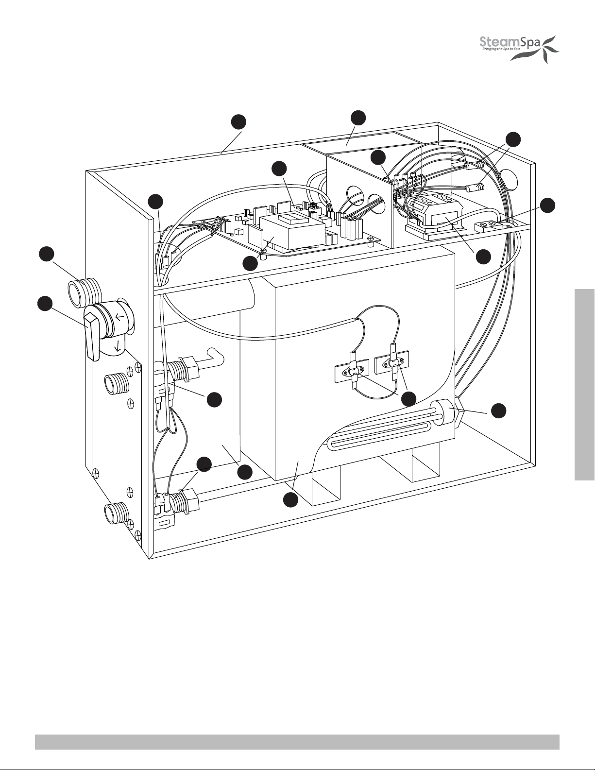
STEAM GENERATOR DISSECTION DIAGRAM
12
3
4
6
5
7
13
14
12
9
11
8
10
15
17
16
1. ENCLOSURE
2. INSULATION BRACKET
3. CIRCUIT BOARD
4. STEAM OUTLET
5. PRESSURE RELIEF VALVE
6. WATER FILL VALVE
7. WATER DRAIN VALVE
8. SUBSIDIARY WATER TANK
9. MAIN WATER TANK
10.HEATING ELEMENT
11.221 F HI-LIMIT
12.TRANSFORMER
13.TERMINAL BLOCK
14.FUSE
15.GROUND WIRE CONNECTOR
16.RELAY
17.WATER LEVEL SENSOR

SteamSpa PHONE: 800-856-0172 FAX: 866-560-1060 http://steamspa.com [email protected]
Page 16
INSTALLATION & USER GUIDE
CARE & USE FOR THE CONTROL PANEL
1. Use soft cloth with a little soap water to clean the control panel.
2. Do not use crude cleaning tools.
3. If the decorating facade is damaged, contact service electrician to change it.
Do not install any SteamSpa controls without reading and understanding the SteamSpa generator Installation and Instruction
manual. Failure to read and understand these instructions will result in inoperative control, generator, hazardous overheating, and/
or inadequate heating of the steam room.
Do not route control wiring inside or close to power lines conduit, hot water or steam piping. Doing so may result in an inoperative
control, generator, and/or hazardous installation.
Do not install SteamSpa controls with other than SteamSpa compatible steam generators. Doing so may result in possible
generator damage or inoperative installation.
Single Control Panel with Temperature sensor must be installed inside bathing area 5 feet above floor. Do not install Control
directly above Steam Head or below shower head but rather in the seating area on a vertical wall. Doing so may result in improper
temperature reading and/or inoperable control.
Turn power to the steam generator off before connecting the control to the generator. Failure to turn the power off generator prior
to connecting controls will result in an inoperable control.
Discontinue use of the steam generator or control if the steam generator is damaged. Continue to do so may result in an
inoperative or hazardous installation.
CONTROLLER BOX CONTENT
• One (1) SteamSpa Black Control Console
• Two (2) Chroma Color Light
• One (1) LED White Light
• Two (2) Shower Speakers with Grills
• One (1) Rim Extension
• One (1) Control Box
• Four (4) Extension Cables
• User guide

SteamSpa PHONE: 800-856-0172 FAX: 866-560-1060 http://steamspa.com [email protected]
Page 17
INSTALLATION & USER GUIDE
1. 7
WITH EXTENSION RIM
NO EXTENSION RIM
0
0 . 9 2 I NCH
I NCH
0.89 I NCH
4. 37 I NCH
4. 7 8 INCH
4. 4 1 INCH
4 I NCH
3 . 2 0 I NCH
3 . 1 0 I NCH
2 . 0 7 I NCH
5. 5 4 INCH
1. 7 0 I NCH
0.9 2 INCH
0.31 INCH
5. 54 I NCH
4. 41 I NCH
4 I NCH
4. 37 I NCH
3 . 2 0 I NCH
3 . 1 0 I NCH
CONTROLLER SPECS
SteamSpa PHONE: 800-856-0172 FAX: 866-560-1060 http://steamspa.com [email protected]
Page 18
INSTALLATION & USER GUIDE
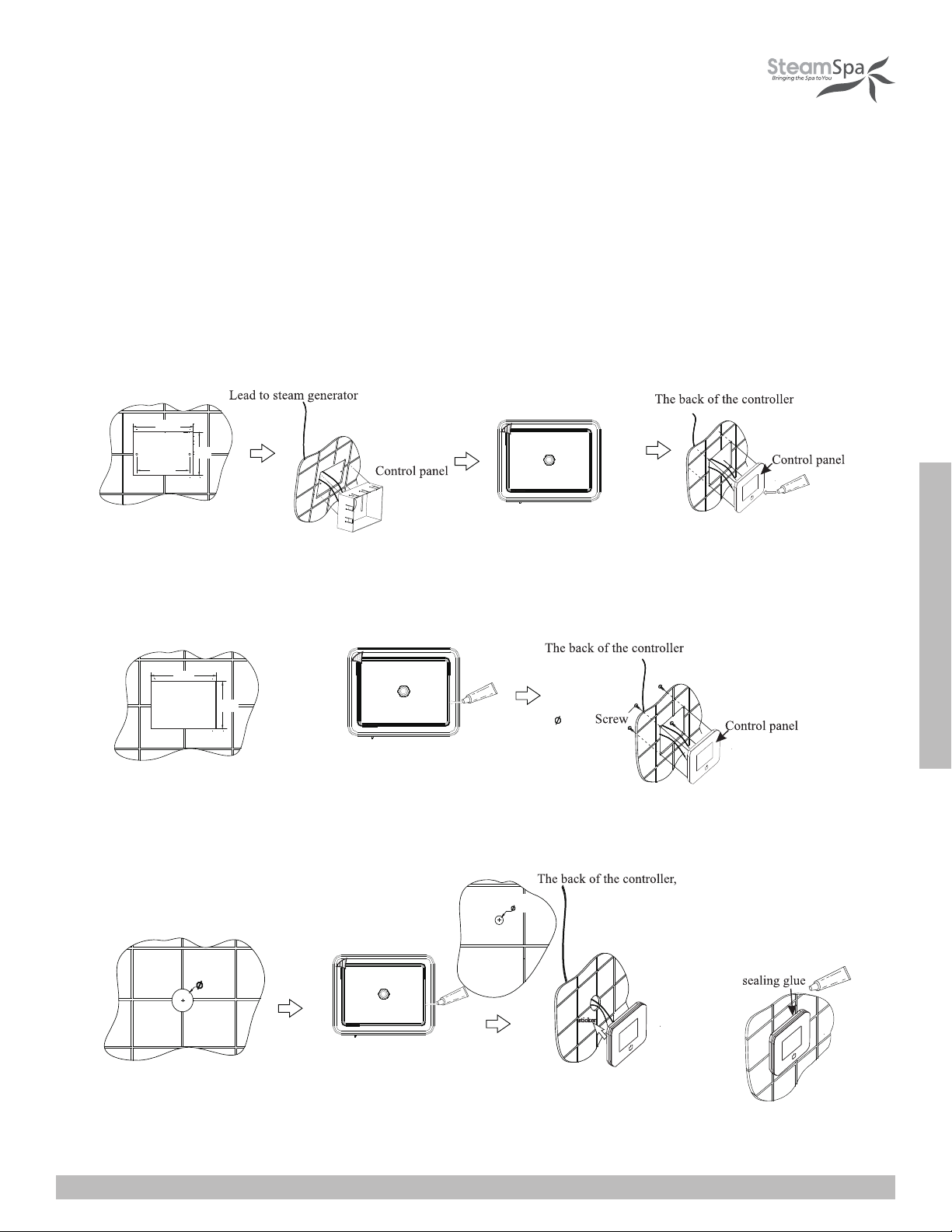
CONTROL PANEL INSTALLATION INSTRUCTIONS
STEP ONE
Determine the installation location of the control panel. The master control panel is designed to be installed in the steam room only,
please install:
1. 4-5 feet from the ground.
2. Keep away from the steam head and do not expose under the direct spray of steam.
3. Install in the perpendicular wall.
4. The position of installation should facilitate easy operation and convenient wiring.
Create the hole for control
box. Make it 47 to 50 inches
from the ground.
Create the hole for mounting
plate. Make it 47 to 50 inches
from the ground.
Open a hole as shown above.
Make it 47 to 50 inches from
the ground.
A. Recess mount onto the wall using the control box.
B. Recess mount with mounting plate.
C. Using the double-sided adhesive.
Place control box into the
hole. Insert screws to hold
control box in place.
Fix the control panel to the control
box. Add a bead of silicone around
the edge to seal.
Fix the control panel to
the mounting plate.
Apply the sticker to the back
of the controller. And press
onto the wall.
Apply the double sided tape.
Apply the double sided tape to the
back. And add a bead of silicone
around the inner lip to seal.
Apply the double sided tape to the
back. And add a bead of silicone
around the inner lip to seal.
Make sure to add the extension rim
behind the control panel’s edge.
1.25”
.4”
4.5”
3.3”
4.72”
3.5”
2.95”
.15”

SteamSpa PHONE: 800-856-0172 FAX: 866-560-1060 http://steamspa.com [email protected]
Page 19
INSTALLATION & USER GUIDE
LED LIGHT
FUNCTIONS
OPERATIONAL APPROACH
BLUETOOTH
STEAM
CHROMA LIGHT
1.START-UP/SWITCH OFF
POWER ON
START-UP
The control panel will BEEP when it’s connected to a power source.
When the system is under stand-by mode, press the key to start-up. The current
ambient temperature in the room and bluetooth music icon will be displayed on the
screen as shown in Figure 1. After the interface is fully displayed, press the function
key on the screen to unlock.
If a user has set the a scheduled start up function, when the secduled time arrives, the
system will start-up automatically and begin the process of producing steam.
Press the key to power down the control panel and enter standby mode. During this
mode the clock will be displayed on screen.
The system will power-off automatically when the pre-set time is reached. (The
system will be shut down after 2 minutes of the steam function closed.)
POWRE-OFF
2.Control of White LED Light (If Equipped)
After power-on, the lighting section interface is shown in Figure 4 as follows: Press
to turn on the light ; Press to turn off the light.
3.Control of Color Changing Light (If Equipped)
When the system is power-on, enter in the lighting interface as shown in Figure 4:
Press key to turn on the Color-Changing light, and then press key to
change the color of the light. Press the key to turn off the Colored-light Function
after the color-changing light function is started.
SteamSpa PHONE: 800-856-0172 FAX: 866-560-1060 http://steamspa.com [email protected]
Page 20
INSTALLATION & USER GUIDE
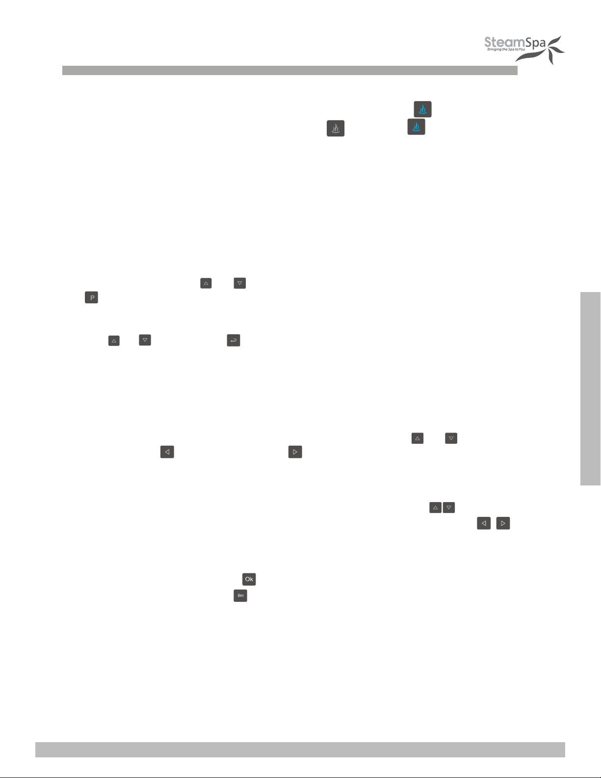
4.STEAM FUNCTION
Select the steam interface shown in Figure 1 after power-on: Press to start the
steam function; The steam key is shown as Figure ; Press the again to stop
the steam Function.
Steam temperature setting: Set temperature by pressing the key of "temperature+" or
"temperature-". Steam time Settings: Set to 5-60 minutes of steaming in 5 minute steps
by pressing the “time+” or “time-” keys.
Save user information: Through the user interface shown in Figure 5; select the user
bar to be used by pressing or key, then save your temperature and timing by pressing
the button.
To select your setting: Through the user interface shown in Figure 5: Select the setting to be used
with the or key, and press to select the saved user setting.
Scheduled start-up setting: Select the function bar of "Working Mode" shown in
Figure 6 on the setting interface, press OK key to enter the interface shown in Figure 7
to set relative parameters.
① Time setting: Stop the cursor on the desired “Timing” by using the or key, set
hours by pressing key, and minutes by key. The parameters are set in loop
with 1 hour increments and a range of 0-23 hours; And a 10 minute increments and a
range of 0-50 minutes.
② Working mode: Move the cursor from Sunday to Monday bar with key, Then
select the function options of: off, one-time schedule, or repeat schedule with
key. If the one-time schedule mode is selected, the system will change the
setting to “off ”automatically after one-time scheduled cycle is complete.
③ Save information by pressing key and run as per the set parameters. Exit the
setting interface by pressing the key.
④ When system is running under the scheduled start-up mode, the temperature and
steamer working time set by user1 shall be taken as default. For example, if the
temperature is 110℉and the working time is 30 minutes set by user1, then the
temperature shall be 110℉and the working time shall be 30 minutes under the
scheduled start-up mode. If the working time is adjusted after start-up, the scheduled
shut off time shall subject to the final set time.
This manual suits for next models
5
Table of contents
Other SteamSpa Inverter manuals

Popular Inverter manuals by other brands

SolaX Power
SolaX Power ZDNY Series user manual

Sunbeam
Sunbeam Luna installation manual

Freedom Won
Freedom Won Encore 8K user manual

Eaton
Eaton Cutler-Hammer SPI9000 user manual

Alpha Group
Alpha Group OutBack Power GS3548E installation manual

EINHELL NEW GENERATION
EINHELL NEW GENERATION STE 5000D operating instructions


