Falco Systems WMA-IB-LN User manual

USER MANUAL
●Drive 2 WMA-200 high voltage amplifiers to 700Vpp output voltage in
bridge mode
●Ultra low noise: with 2 WMA-200 high voltage amplifiers ~105µVrms
●Fully differential signal path and connectors + additional BNC input
●DC – 100kHz power bandwidth with two WMA-200 amplifiers
●±10V maximum differential input and output voltage
About this manual
This user manual is an integral part of the
Falco Systems WMA-IB-LN ultra-low noise
phase inverter - buffer product. Please
read it carefully and pay attention to the
recommendations and instructions for safe
use.
Operation of the phase inverter
The WMA-IB-LN is an ultra-low noise
phase inverter – buffer designed to drive
one or two Falco Systems WMA-200 high
voltage amplifiers. It can be used:
!To drive two amplifiers in bridge mode by
using both the buffered output and the
inverting output, or
!As a buffer between a signal source
and the amplifier
The BNC and differential input can be
used with signals up to ±10V input voltage.
The signal on the BNC connector is
converted to a differential signal to drive
the high voltage amplifier(s). The
differential outputs have a low impedance
and are short-circuit protected.
The WMA-IB-LN ships with a customized
Mean Well GS25B28-P1J power supply.
The power supply connector, 315mAT
fuse and on-off switch are on the rear
panel of the WMA-IB-LN enclosure. A blue
led indicates that the WMA-IB-LN is on.
The outputs are on the left of the front
panel to accommodate neat cabling to
high voltage amplifiers that typically have
their inputs on the left side too.
Bridge mode
The WMA-IB-LN can be used to double
the maximum output voltage driving a
load, such as a piezo actuator, EO
(electro-optical) modulator, or MEMS
(electromechanical systems) device,
among many others. This is achieved by
driving two high voltage amplifiers both
Falco Systems WMA-IB-LN Ultra-Low Noise Phase Inverter - Buffer

with the same signal, but with opposite
polarity. The outputs of the amplifiers are
connected in bridge mode. Fig. 1 shows
the concept of the bridge mode circuit.
Figure 1. Doubling the maximal output
voltage by using ‘bridge mode’
The WMA-IB-LN inverts the signal and
provides the signal for both amplifiers. The
outputs of the two amplifiers are
connected to the floating, ungrounded
load. The WMA-IB-LN phase inverter -
buffer amplifies 1x. If both amplifiers
amplify e.g. 20x, the total output voltage
across the load will be doubled in bridge
mode, i.e. 40x in this case.
Fig. 2 shows an actual setup with the ultra-
low noise phase inverter buffer connected
to two high voltage amplifiers to drive them
in bridge mode.
Figure 2. Connecting the high-speed
phase inverter buffer and two amplifiers for
bridge mode operation
When two amplifiers are driven in bridge
mode, the high voltage output signal with
twice the amplitude of the individual high
voltage amplifiers is available between the
inner pins of the two high voltage amplifier
BNC outputs and can be connected to the
load (Fig 3). Make sure that the load is not
grounded to the same ground as the
amplifiers, as this would short-circuit one
of the two high voltage amplifiers. This will
not damage the amplifier (if it is short-
circuit proof) but would reduce the output
voltage available to that of a single
amplifier only.
Figure 3. Connecting a load in bridge
mode to two WA-200 high voltage
amplifiers
Connecting the load
The ultra-low noise phase inverter - buffer
in combination with two Falco Systems
high voltage amplifiers is capable of both
relatively high bandwidth and ultra-low
noise performance. This performance can
only be obtained with correct shielding of
the cables connecting to the load and, if
possible, shielding of the load itself. Solid
BNC connectors and/or short, high quality
BNC cables are recommended.
Some loads, such as certain EO-
modulators, have a differential connector
available, or two individual connectors, to
drive them differentially (Fig. 4).
Figure 4. Shielded, differentially driven
load for bridge mode operation
The housing of the modulator is connected
to the shield of the cables this way,
resulting in good interference rejection.
-1x
Vin
Amp Amp
Load
Load%
Load
Cable 1 Cable 2
Shielding enclosure

This scheme is also the recommended
one if the user has the possibility to design
the connections of the load him/herself.
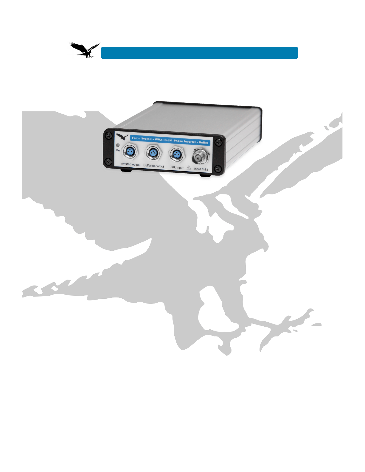
In situations where driving the load
differentially with two connectors is
impossible, e.g. because the load has a
single connector, both amplifier outputs
have to be connected together at the load,
as depicted in Fig. 5.
Figure 5. Driving a single-connector load
in bridge mode
If one of the two connections of the
connector is connected to the (conductive)
housing of the load, check that
!the housing/outside of the load floats
with respect to the ground of the
amplifiers, i.e. it makes no contact with the
electrical circuit to which the amplifiers
belong, other than via the output cables,
and
!the housing/outside of the load and the
BNC connector itself cannot be touched,
as it carries the full output voltage of one
of the high voltage amplifiers. For this
reason the sign is present on the type
plate of the enclosure of the WMA-IB-LN.
The use of an insulated BNC connector is
recommended.
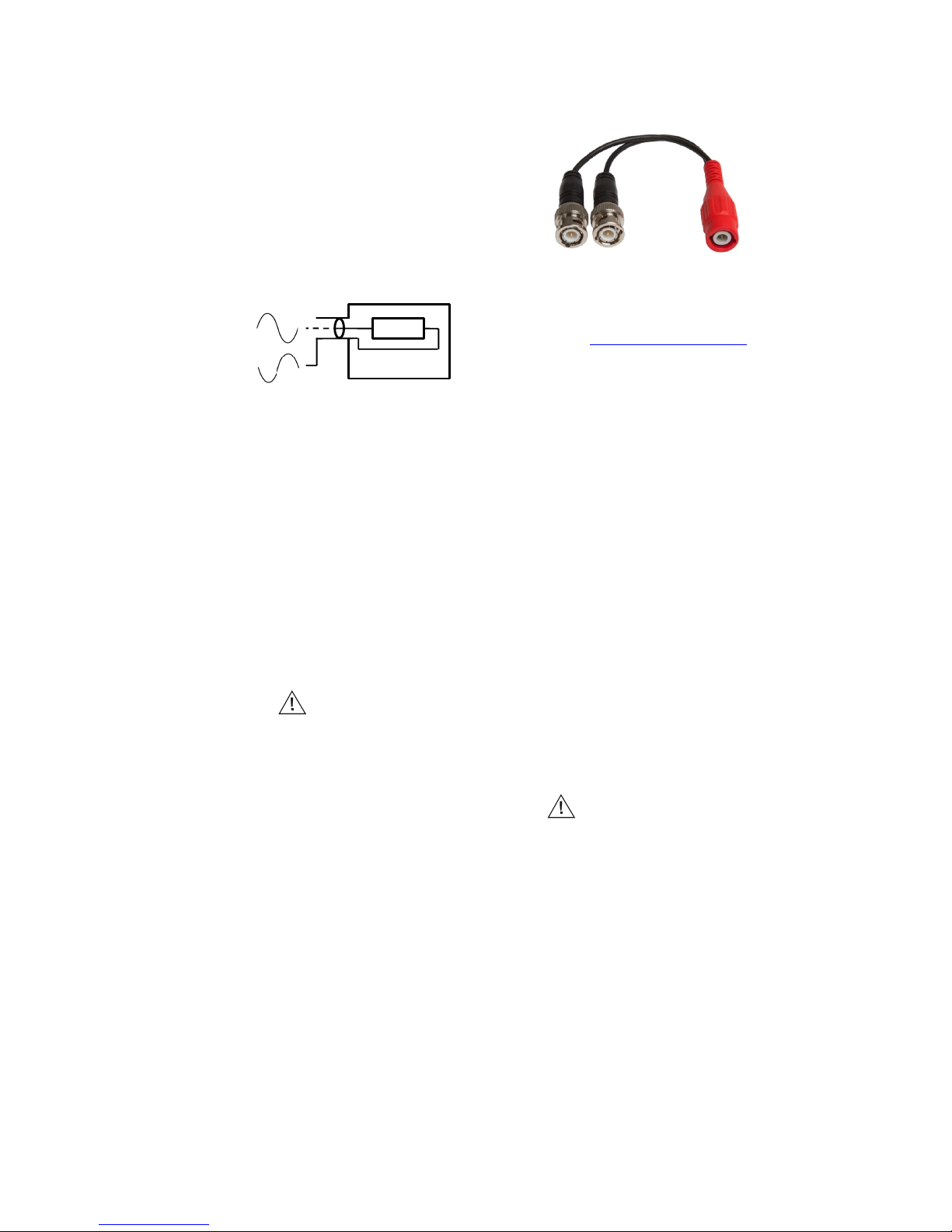
To aid in connecting floating loads in
bridge mode, Falco Systems offers a
special ‘bridge mode insulated tee-cable’
(Fig. 6). This cable takes the two amplifier
cables on BNC connectors, and has a
third BNC connector, where the inner
conductor of one input cable is connected
to the inner pin, and the inner conductor of
the other cable to the outer ring, which is
normally associated with the 0V shield.
This functionality is very different from a
normal BNC tee-adapter, which is only
used to connect the inner conductor of a
BNC cable to two cables, with all inner
pins connected together.
Figure 6. A ‘bridge mode’ tee-cable for
connecting the load is available from Falco
Systems, and can be purchased on the
website www.falco-systems.com
Required amplifier properties
The WMA-IB-LN phase inverter - buffer
has been designed for use with the ultra-
low noise Falco Systems WMA-200 high
voltage amplifiers. Another model, the
Falco Systems WMA-IB-HS high speed
phase inverter – buffer is a better choice
for use with most other high voltage
amplifiers due to its larger bandwidth,
switchable input impedance, and BNC
connectors.
Recommendations and safety
Recommendations:
!Heed the advice in the ‘connecting the
load’ section of the manual. In short: do
not short circuit one of the amplifiers by
grounding the load, and make sure the
voltage-carrying parts of the load cannot
be touched during operation
!Never apply more than +10V (or less
than -10V) to the phase inverter/buffer
input to prevent damage. This is indicated
by the sign between the two inputs.
!The phase inverter/buffer cannot be
damaged by a short-circuit condition or
capacitive loading, but two situations
should be avoided:
- Connecting a charged capacitor to the
input or output.
- Connecting a highly inductive load to
the output (such as a coil).
!Do not connect anything to the phase
inverter/buffer that can act as an antenna.
!This product should only be cleaned with
a soft, slightly moist cloth. Disconnect the
phase inverter/buffer from the power
supply and all equipment before cleaning.
Load
Cable inner
conductor
Enclosure
Cable outer
shield
Cable

Safety:
!The Falco Systems WMA-IB-LN ultra-low
noise phase inverter - buffer is only
suitable for indoor use in a class II
environment (domestic, light industrial).
!Use the power supply adapter supplied
by Falco Systems only: Mean Well
GS25B28-P1J, 100-240V~ 50/60Hz in,
28V 25W DC out, with custom MiniDIN
connector
!Only replace fuses with the correct type:
5x20mm 315mAT 230V fuse on the rear
panel
!This product cannot be powered by non-
sinusoidal mains power generators.
!Only replace a damaged power cord with
an equivalent type: H03VVH2-F 2X 0,75
mm2, with Euro to C7 equipment
connector
!The airflow to and from the WMA-IB-LN
should not be blocked or impeded, to allow
for adequate ventilation
Transmitter mode
This high speed phase inverter - buffer
can generate a significant amount of
power at frequencies used for radio
transmission and reception. It should not
be used for telecommunication as
described in the R&TTE directive 95/5/EC.
Always use shielded cables.

WMA-IB-LN Ultra-Low Noise Phase Inverter - Buffer characteristics
Figure 7. Buffered output signal of the WMA-IB-LN; 10kHz 16Vpp differential square wave
signal
Figure 8. Inverted output signal of the WMA-IB-LN; 10kHz 16Vpp differential square wave
signal
Figure 9. Bandwidth of the WMA-IB-LN from input to output, stand-alone operation
-15
-10
-5
0
5
10
15
250200150100500
Time%(μs)%
Differen.al%output%voltage%(V)%
Time%(μs)%
Differen.al%output%voltage%(V)%
-15
-10
-5
0
5
10
15
250200150100500
!"#$%#&'()*+,-)
1.0
0.8
0.6
0.4
0.2
102103104105106107
./0&)

Figure 10. Bandwidth of the WMA-IB-LN when used with two WMA-200 high voltage
amplifiers in bridge mode. Shown is the measured bandwidth of a 600Vpp differential sine
wave signal between the two WMA-200 high voltage amplifier outputs
Figure 11. Measured differential output voltage noise between two WMA-200 high voltage
amplifier outputs, with short-circuited WMA-IB-LN inputs. The effective differential voltage
noise between the two WMA-200 high voltage amplifier outputs is 130µVrms measured in a
bandwidth of DC - 1MHz bandwidth, and 105µVrms in a bandwidth of DC - 100kHz.
600
500
400
300
200
100
0
102103104105106107
!"#$%#&'()*+,-)
./0#"#&123)4%56%5)743528#)*966-)
400
200
0
-200
-400
50403020100
Time%(ms)%
Differen-al%output%voltage%(μV)%

Technical specifications
Inputs: 1kΩ0.1% input impedance, ±10V max input voltage; single-ended BNC and
differential connector
Outputs: ±5V maximum output voltage (differential ±10V), short-circuit proof
Gain: buffered out: +1x, inverted out: -1x. The single ended BNC signal will appear buffered
and inverted on the two outputs with 0.5x gain each, making a total differential gain of 1x
Bandwidth DC – 100kHz @-3dB typical at the WMA-200 high voltage amplifier outputs
Differential output noise between the WMA-200 high voltage amplifier outputs: ~130µVrms
measured in a bandwidth of DC - 1MHz bandwidth, and ~105µVrms in a bandwidth of DC -
100kHz
Operating temperature: 15 – 30°C
Storage temperature: 0 – 60°C
Relative humidity: 30 – 70% non-condensing
Maximum usage height: 2000m
Dimensions and weight: 190x106x34mm, 0.4 kg
Power: 28V DC, 200mA maximum, with 315mAT 5x20mm 230V fuse and on/off switch on
rear panel. Use the power supply adapter supplied by Falco Systems only: Mean Well
GS25B28-P1J, 100-240V~ 50/60Hz in, 28V 0.75A DC out, 25W, with custom MiniDIN
connector
Country of origin: The Netherlands
Specifications may be subject to change
Harmonized standards
This prototype product complies with the
following standards:
Safety: EN61010-1
EMC: EN61326
The mark is present on the WMA-IB-
LN device to indicate compliance of this
equipment with the European Union safety
and EMC regulations, while the mark
has been added to indicate compliance
with the United States FCC regulations.
WEEE and RoHS
Do not dispose of this product as standard
waste, but bring it to a WEEE electronic
waste collection point. This is indicated by
the sign on the WMA-IB-LN. The
WMA-IB-LN has been built in compliance
with the RoHS directive.
Warranty
Falco Systems products are guaranteed
against malfunction due to defects in
materials or workmanship for a period of 1
year from the date of shipment.
If a malfunction occurs during this period,
the product will be repaired or replaced
without charge. The product will be
returned to the customer prepaid.
The warranty does not apply to:
!Exterior finish or appearance
!Malfunction resulting from use or
operation of the product in other ways than
specified in the user manual
!Malfunctioning due to misuse or abuse of
the product
!Malfunctioning occurring after changes
or repairs have been made by anyone
other than Falco Systems.
To obtain warranty service, the customer
has to inform Falco Systems first via
info@falco-systems.com to receive further
instructions.
Falco Systems will not be liable for any
consequential damages, including, without
limitation, devices or equipment connected
to the product, injury to persons or
property or loss of use. See for more
details the Falco Systems Standard Terms
and Conditions of Sale, which can also be
obtained via info@falco-systems.com.

User manual version
User manual version: 1.2
Date: October 29, 2018
Falco Systems
Falco Systems
Remisestraat 1
2225 TH Katwijk aan Zee
The Netherlands
Tel. +31 (0)6 21840996
Fax. +31 (0)20 2031445
Email: info@falco-systems.com
www.falco-systems.com
Table of contents
Other Falco Systems Inverter manuals
Popular Inverter manuals by other brands

Wen
Wen GN9500 instruction manual

Mastervolt
Mastervolt WHISPER 16 ULTRA user manual

Schweizer
Schweizer MSP-FR-EW Mounting instructions

LG
LG LG N3K-V6 Series installation manual

SALUPO
SALUPO SOFT START PLUS 1 Instruction and installation manual

Scheppach
Scheppach SG1200 Translation from the original instruction manual