Deimic One Master User manual

INSTALLATION GUIDE


Thank you for choosing the DEIMIC products.
We hope that this instruction will help you
to perform the device installation by yourself.
In case of any trouble please contact us:
www.deimic.com

CONTENT
WARNINGS 3
1. DEiMiC ONE MASTER DEVICE SPECIFICATION 4
1.1. DESCRIPTION 4
1.2. TECHNICAL DATA 5
1.3. DEIMIC ONE MASTER PINOUT DESCRIPTION 6
1.4.
DEIMIC ONE EXPANDER PINOUT DESCRIPTION 8
1.5. APPLICATIONS 10
2. ASSEMBLY 11
2.1. PREPARATION TO ASSEMBLY 11
2.2. GUIDELINES 11
2.2.1. Wires 12
2.2.2. Electrical switchgear 17
2.2.3. Connections inside electrical switchgear 17
2.2.4. Marking 19
2.2.5. Good advices 19
3. EXAMPLES OF WIRING DIAGRAMS 20
3.1. OUTPUTS CONNECTION – SHUTTERS 20
3.2. OUTPUTS CONNECTION – CONTACTORS 21
3.3. OUTPUTS CONNECTION - LIGHTS 22
3.4. POWER SUPPLY CONNECTION 23
3.5.
INPUTS CONNETION – SWITCHES AND BUTTONS
24
3.6. OUTPUS CONNECTIONS – LED LIGHTS 25
3.7. MOVING SENSORS CONNECTION 26
3.8. NETWORK CONNECTION
27
3.9.
OUTPUTS CONNECTIONS – GATES, GATEWAYS
28
3.10. EXTENSIONS MODULES CONNECTION 29
3.11. ALARM CONNECTION 30
4. FIRST START 31
4.1. Test button 31
4.2. DEiMiC ONE MOBILE APPLICATION 31
4.3. FIRST START OF DEiMiC ONE APPLICATION 31
5. GUIDELINES 32
5.1. ROLLER BLINDS, SHUTTERS AND MARQUISE 32
5.2. GATE DRIVERS 33
5.3. CENTRAL HEATING 33
6. REVISION HISTORY 35
7. INSTALLER NOTES 36
8. WARRANTY 38
TERMS OF THE WARRANTY 38
9. PRODUCT REMARKS 39
10. REPAIRS 40

This instruction is a part of the product and
shall be kept for future reference. Before instal-
lation you should read product documentation,
which contains important information on
the device settings and operation.
The module is comply with EU directives,
including EMC 2004/108/EC, LVD2006/95/
EC. Declaration of Conformity is available
on www.deimic.com.
The producer takes no responsibility for dam-
ages caused by inappropriate usage of the de-
vice, inappropriate assembly or not obeying
assembly instructions.
The installation must be performed in accordance
with every safety standards for electrical installa-
tions and electrical regulations.
The device should be installed by qualied elec-
trician.
Every installation work should be done with
power o.
Every repairs must be performed be authorized
service only. Device modications or repairs
done by anyone who is not authorized by
the producer are forbidden and means lose
of the warranty.
To avoid risk of electrical shock never open
the device and do not touch any inside compo-
nents of the device with your hands.
For safety reasons it's necessary to obey all
the instructions in this document. Failure to
follow these instructions may result in death
or serious injury.
DEiMiC company products are not intended
for use in medicine, avionics and industry.
DEiMiC company devices should be installed
inside rooms, in places available for a tter
and conservator.
Remember to ensure proper ventilation for
the device and do not expose it to the eects
of weather conditions.
Because of continuing products development,
the producer reserves the right to change
and modify the device and its documentation
without notice.
Utilization of waste electrical and electron-
ic equipment is regulated by the EU directive
2002/96/EC.
The Directive prohibits disposal of waste
electrical and electronic equipment with other
garbage under penalty of a ne.
According to the law, worn out devices must
be separately collected and sorted. Custom-
ers should contact their local authorities
or the seller to get information about disposal
of a waste electrical and electronic equipment.
WARNINGS

The DEiMiC system will intergrate all electrical equipment in your home! Remote control will make your
live easer and a brief description will familiraze you with our special product.
Following the ideal, we developed a device adjusted to individual needs of every our client - there is no
need for making compromises. The system was developed basing on exibility, comfort and easy-in-
stallation criteria. There is also a possibility of expanding the system capabilities by additional Expander
modules.
1. DEIMIC ONE MASTER DEVICE SPECIFICATION
1.1. DESCRIPTION

1.2. TECHNICAL DATA
DEIMIC ONE MASTER Value
Relay outputs 39
LED outputs 4
Digital inputs 55
Maximum number of modules in system 1
Gate outputs up to 4
Heating control up to 10 sections
LAN port 1
USB port 1
Recuperator control Yes
Alarm control Yes
DEIMIC ONE EXPANDER Value
Relay outputs 39
LED outputs 4
Digital inputs 55
Maximum number of modules in system 10
Gate outputs -
Heating control up to 10 sections
LAN port -
USB port -
Recuperator control Yes
Alarm control -

1.3. DEIMIC ONE MASTER PINOUT DESCRIPTION


1.4.
DEIMIC ONE EXPANDER PINOUT DESCRIPTION

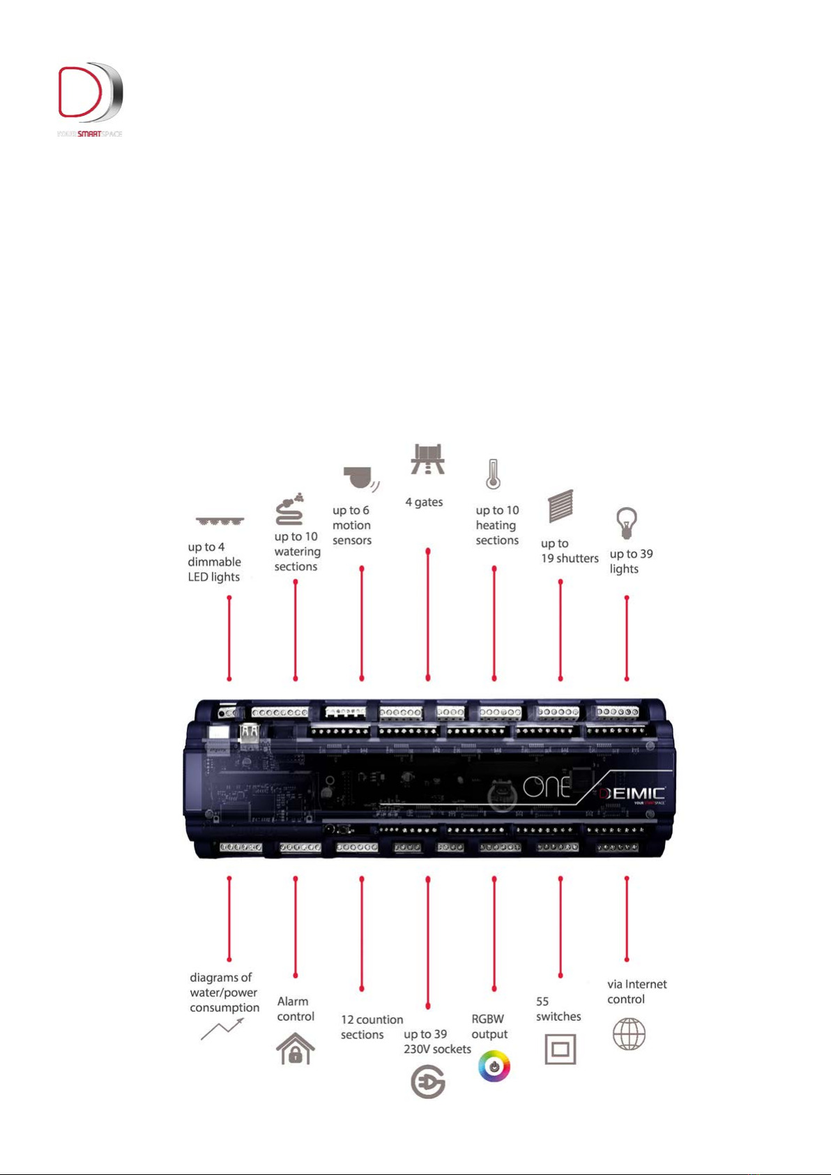
1.5. APPLICATIONS
DEiMiC smart home system provides control of all electrical devices inside a building such
as lights, shutters, car gates and garage gates, heating devices, alarms, irrigation devices,
ventilation and sound systems. The device is cooperating with motion sensors, temperature sensors
and switches. Thanks to LAN network connection, the DEiMiC system can be controlled via
tablet or smartphone, providing the user all information about the system state from almost
every place in the world.

2.1. PREPARATION TO ASSEMBLY
During assembly the following tools may be useful:
phillips screwdriver,
slotted screwdriver,
precision pliers,
at pliers,
driller,
drill-driver,
nippers for cable cutting,
digital multimeter,
connectors crimper,
cable stripper,
soldering tool.
Before assembly it is recommended to prepare a object plane. Preparation of the object
plane and putting there all system devices, switches and sensors will make easier future work.
2. ASSEMBLY
EVERY INSTALLATION WORK SHOLUD BE DONE WITH POWER OFF
BEFORE ASSEMBLY, IT IS NECESSARY TO READ THE INSTRUCTION, ESPECIALLY
THE WARNINGS ON PAGE 1
2.2. GUIDELINES
During wires installation it is recommended to ensure appropriate space between low-voltage
wires and mains electricity wires. It is recommended to avoid situations where signals
wires are placed parallel to the mains electricity wires.
The control cabinet should be protected against unauthorized access.

2.2.1. Wires
You should use good quality cables only. Choose UTP cat. 5 cables which are made from copper.
Do not use shielded cables to the switches, especially high-class cables
Every wire connection which diers from above rules must be consulted with the system installer.
1. All standard light sections should be routed
from an electrical switchgearwith a 3x1,5mm2
wire or other according to the lampproducer
recommendations.
2. Every roller blinder, marquise, shutter should
be routed directly to anelectrical switchgear
with 4x1,5mm2wire or other according to
the driver producer recommendations.
3. Gate driver should be routed from an electrical
switchgear accordingto producer specication
UTP cat. 5 cable to the controller.
4. Every motion sensor should be connected with
another UTP cat. 5 cabledirectly from an electrical
switchgear.
5. One UTP cat. 5 cable should be placed between
Ethernet router and anelectrical switchgear.
6. A 1,5mm2multi-conductor cable should be
lead to heating distributors(number of the cable
conductors = quantity of valves + 2).
7. A UTP cat. 5 cable should be placed in
the all switch boxes directly froman electrical
switchgear (if any localization have more than
6 buttons, it necessary to add one more
UTP cat. 5).
8.A UTP cat. 5 cable should be lead to the tempera-
ture sensors directly froman electrical switchgear.
9.Chosen switchable electric socket should be
connected directly do anelectrical switchgear.
10. LED and RGB lighting circuits – Power sup-
pliers should placed in anelectrical switchgear;
connection: 2 or 4 multi-conductor cable with
cable cross-section adjusted to cables length
and lighting power.
11. Gelled wires only should be placed inside
ground and outside the object.
12. A UTP cat. 5 wire form an electrical switchgear
should be lead to a gate electro connector.


2.2.3. Connections inside electrical switchgear
2.2.2. Electrical switchgear
The control cabinet should be protected against unauthorized access
1. Dimensions of an electrical switchgear should
be adjusted to quantity onstallation modules
and protections. One DEiMiC module uses space
of 18 modules.
2. Electrical equipment, protective and re-
sidual-current devices should bechosen and
installed by a electrician only.
3. One protection should be done for every
6 lighting circuits.
4. One protection should be done for every
6 shutters.
5. DEiMiC system needs one B6 circuit breaker.
6. Whole electrical switchgear must be described
in details and sent to ainvestor.
1. Every building outgoing wire, which are
not controlled by the DEiMiC system (electric sock-
ets, furnace, alarm, fridge power supplies etc.)
should be connected to circuits breakers
like in traditional installations.
2. Circuits controlled by DEiMiC system should be
connected according to following rules:
a) Neutral wires connected on terminal strips com-
ply with residual-current devices.
b) Ground wires connected to grounded strips.
c) Lighting hot wires led out at single terminal.
d) Shutters hot wires led out at two single
terminal, where rst one sets the direction
up (apply the same rule for roof windows and
other mechanisms where direction is controlled
by wire connection sequence), second one
– the direction down.
e) Switchable electric sockets hot wires led out
at single terminal.
f) Switches UTP cables led to an electrical switch-
gear with description and enough free space to al-
low access for every place in the switchgear.
g) Sensors UTP cables led to an electrical
switchgear with description and enough free
space to allow access for every place in the
switchgear.
h) Temperature sensors cables led to an elec-
trical switchgear with description and enough
free space to allow access for every place in
the switchgear.
i) Heating distributors outgoing wires should be
connected with valves, insidehermetic boxes,
led out with terminal form an electrical switch-
gear side and described according to docu-
mentation delivered by central heating installer
(room names assigned to the valves).
j) All terminals leading out to devices which are
power supplied by voltage lower than 230V should
be marked and dierent terminal colors should be
used.

Other manuals for One Master
1
Table of contents
Other Deimic Home Automation manuals


