DELAIR UX5 HP User manual

USER GUIDE
UX5 HP AERIAL IMAGING SOLUTION
Version 2.2.8
Revision A
October 2017
Delair-Tech |676, Rue Max Planck – 31670 Toulouse-Labège, France |Tel: +33 (0) 5 82 95 44 06 |www.delair.aero
Capital: 238 110,30 € - APE: 3030Z – Intra-Community VAT number: FR90 53 09 69 781 – 530 969 781 R.C.S. Toulouse
This document is the sole property of Delair-Tech and cannot be used or reproduced without the written authorization of Delair-Tech. 1
Legal Information
Delair-Tech SAS
www.delair.aero
Copyright and Trademarks
© 2017, Delair-Tech SAS. All rights reserved.
Delair and its logo are trademarks of Delair-Tech SAS
registered in France and in other countries.
Microsoft and Windows are either registered trademarks
or trademarks of Microsoft Corporation in the United
States and/or other countries.
The Bluetooth word mark and logos are owned by the
Bluetooth SIG, Inc. and any use of such marks by Delair-
Tech SAS is under license.
Wi-Fi is a registered trademark of the Wi-Fi Alliance.
All other trademarks are the property of their respective
owners.
COCOM Limits
The U.S. Department of Commerce requires that all
exportable GPS products contain performance limitations
so that they cannot be used in a manner that could
threaten the security of the United States. The following
limitations are implemented on this product:
– Immediate access to satellite measurements and
navigation results is disabled when the receiver velocity is
computed to be greater than 1,000 knots, or its altitude is
computed to be above 18000 meters. The receiver GPS
subsystem resets until the COCOM situation clears. As a
result, all logging and stream configurations stop until the
GPS subsystem is cleared.
Notices
United States
Certification number:
FCC ID HSW-DNT2400P.
This equipment has been tested and found to comply with
the limits for a Class A digital device, pursuant to part 15 of
the FCC Rules. These limits are designed to provide
reasonable protection against harmful interference when
the equipment is operated in a commercial environment.
This equipment generates, uses, and can radiate radio
frequency energy and, if not installed and used in
accordance with the instruction manual, may cause
harmful interference to radio communications. Operation
of this equipment in a residential area is likely to cause
harmful interference in which case the user will be
required to correct the interference at his own expense.
Changes and modifications not expressly approved by the
manufacturer or registrant of this equipment can void
your authority to operate this equipment under Federal
Communications Commission rules.
Canada
Under Industry Canada regulations, this radio transmitter
may only operate using an antenna of a type and
maximum (or lesser) gain approved for the transmitter by
Industry Canada.
To reduce potential radio interference to other users, the
antenna type and its gain should be so chosen that the
equivalent isotropically radiated power (e.i.r.p.) is not
more than that necessary for successful communication.
This device complies with Industry Canada license-exempt
RSS standard(s). Operation is subject to the following two
conditions:
(1) this device may not cause interference, and
(2) this device must accept any interference, including
interference that may cause undesired operation of the
device.
This Class A digital apparatus complies with Canadian
ICES-003.
Certification number: IC 4492A-DNT2400P.
This apparatus complies with Canadian RSS-210.
Conformément à la réglementation d'Industrie Canada, le
présent émetteur radio peut fonctionner avec une antenne
d'un type et d'un gain maximal (ou inférieur) approuvé
pour l'émetteur par Industrie Canada.
Dans le but de réduire les risques de brouillage
radioélectrique à l'intention des autres utilisateurs, il faut
choisir le type d'antenne et son gain de sorte que la
puissance isotrope rayonnée équivalente (p.i.r.e.) ne
dépasse pas l'intensité nécessaire à l'établissement d'une
communication satisfaisante.
Le présent appareil est conforme aux CNR d'Industrie
Canada applicables aux appareils radioexempts de licence.
L'exploitation est autorisée aux deux conditions suivantes:
(1) l'appareil ne doit pas produire de brouillage, et
(2) l'utilisateur de l'appareil doit accepter tout brouillage
radioélectrique subi, même si le brouillage est susceptible
d'en compromettre le fonctionnement.
Cet appareil numérique de la classe A est conforme à la
norme NMB-003 du Canada.
Numérique de certification IC: 4492A-DNT2400P.
Cet appareil est conforme à la norme CNR-210 du Canada.
Europe
The product covered by this guide are intended to be used
in all EU member countries, Norway, and Switzerland.
This equipment is classified as Group 1, Class A equipment
according to EN 55011. Group 1 is applicable for all
equipment within the scope of EN 55011 that is not
classified as Group 2 equipment, which contains all ISM RF
equipment. Class A equipment is equipment suitable for
use in all establishments other than domestic. Using Class
A equipment in domestic environments may cause
difficulties ensuring electromagnetic compatibility.
CE Declaration of Conformity
Hereby, Delair declares that this product is in
compliance with the essential requirements
and other relevant provisions of:
Delair-Tech |676, Rue Max Planck – 31670 Toulouse-Labège, France |Tel: +33 (0) 5 82 95 44 06 |www.delair.aero
Capital: 238 110,30 € - APE: 3030Z – Intra-Community VAT number: FR90 53 09 69 781 – 530 969 781 R.C.S. Toulouse
This document is the sole property of Delair-Tech and cannot be used or reproduced without the written authorization of Delair-Tech.2

– EMC Directive (2014/30/EU)
– Radio Equipment Directive (2014/53/EU)
– RoHS Directive (2011/65/EU)
– Machine Directive (2006/42/EC)
Note– Deviation from Machine directive 2006/42/EC:
The CE marking for the UX5 HP system is placed on the
UX5 HP eBox and is only visible when the eBox is
removed from the UX5 HP wing.
Japan
Certification numbers for the DNT2400P RFM radio
module: 007WWCUL0739 and 003UVA110681
Brazil
Este produto está homologado pela Anatel, de acordo com
os procedimentos regulamentados pela Resolução nº.
242/2000 e atende aos requisitos técnicos aplicados,
incluindo os limites de exposição da Taxa de Absorção
Específica referente a campos elétricos, magnéticos e
eletromagnéticos de radiofrequência de acordo com as
Resoluções nº. 303/2002 e 533/2009.
Manter distância mínima de 2,5 cm do corpo humano.
Para maiores informações, consulte o site da ANATEL
www.anatel.gov.br.
Australia and New Zealand
This product conforms with the regulatory
requirements of the Australian Communications
and Media Authority (ACMA) EMC framework,
thus satisfying the requirements for C-Tick Marking and
sale within Australia and New Zealand.
Taiwan – Battery Recycling Requirements
The product contains a removable lithium polymer
battery. Taiwanese regulations require that waste batteries
are recycled.
廢電池請回收
Waste Electrical and Electronic Equipment (WEEE)
For product recycling instructions and more
information, please fill in a contact form at
www.delair.aero or mail a request for recycling
instructions to:
Delair-Tech
676 rue Max Planck
31670 Toulouse-Labège
France
FCC Declaration of Conformity
We, Delair-Tech SAS,
676 rue Max Planck
31670 Toulouse-Labège
France
+33 5 82 95 44 06
Declare under sole responsibility that DoC
products comply with Part 15 of FCC Rules.
Operation is subject to the following two
conditions:
(1) This device may not cause harmful
interference, and
(2) This device must accept any interference
received, including interference that may cause
undesired operation.
China – Reminder before first use
初次使用前提醒
在第一次使用无人机前,拥有人应当在无
人机实名登记系统 HTTPS://UAS.CAAC.GOV.CN 中
进行实名登记。信息填报后,系统自动给
出包含登记号和二维码的登记标志图片,
并发送到登记的邮箱。请将登记标志图片
打印在不干胶贴牌上(包装中提供)。最
后,登记标志图片应当粘贴在机身中电池
预留位置EPP泡沫材料上。
注意: 不实名登记或不按要求粘贴登记标
志图片而擅自飞行有可能会被追究法律责
任。
Before the first flight, the owner shall register
this system on HTTPS://UAS.CAAC.GOV.CN, a CAAC
(Civil Aviation Administration of China) online
real name registration platform. After having
fulfilled information online, the owner will
receive by email an image consisting in a
registered number and a 2D barcode. This
image should be printed on a sticker provided
in the package and then attached to the EPP
foam underneath the battery in the UAS body.
Please note: The owner is held responsible for
any legal consequence if he or she fails to fulfill
the above obligations.
Delair-Tech |676, Rue Max Planck – 31670 Toulouse-Labège, France |Tel: +33 (0) 5 82 95 44 06 |www.delair.aero
Capital: 238 110,30 € - APE: 3030Z – Intra-Community VAT number: FR90 53 09 69 781 – 530 969 781 R.C.S. Toulouse
This document is the sole property of Delair-Tech and cannot be used or reproduced without the written authorization of Delair-Tech.3

Environmental hazards
The product complies with international RoHS regulations.
Toxic and hazardous substances and elements
Part name Lead
(Pb)
Mercury
(Hg)
Cadmium
(Cd)
Hexavalent
Chromium
(Cr6+)
Poly-brominated
biphenyls
(PBB)
Poly-brominated
diphenyl ethers
(PBDE)
Lithium polymer rechargeable
battery
X O O O O O
Power supply X O O O O O
Printed circuit board assembly X O O O O O
Radio module X O O O O O
Chassis O O O O O O
Plastic enclosure O O O O O O
Paper manual O O O O O O
4
Delair-Tech |676, Rue Max Planck – 31670 Toulouse-Labège, France |Tel: +33 (0) 5 82 95 44 06 |www.delair.aero
Capital: 238 110,30 € - APE: 3030Z – Intra-Community VAT number: FR90 53 09 69 781 – 530 969 781 R.C.S. Toulouse
This document is the sole property of Delair-Tech and cannot be used or reproduced without the written authorization of Delair-Tech.
Contents
1 Introduction 7
The UX5 HP aerial imaging solution 8
System components 9
Installing the Aerial Imaging software 10
Projects, blocks, and flights 12
Project phases 12
Software overview 13
Changing the system settings 16
Performing maintenance 17
2 Planning a Project 19
Designing a flight plan to meet the project requirements 20
Creating a project 23
Preparing the project map 24
Defining the blocks 27
Obstacle clearances 33
Defining the flights 37
Exporting the project 45
Checking flight permissions and conditions 45
3 Preparing Equipment 49
Flight case contents 50
Parts of the UX5HP aerial imaging rover 51
Inserting the eBox and gBox 54
Checking the launcher 56
Checking the rover 56
Charging the UX5 HP batteries 59
Charging the tablet batteries 63
Preparing the camera 63
Binding the tracker transmitter and receiver 67
Locating your equipment 67
4 Completing a Flight 69
Importing the project 70
Keeping an eye on the weather 70
Validating the blocks 70
Validating the flights 70
Completing the flight checklist 71
Launching the rover 83
Monitoring and controlling the rover during flight 84
Landing the rover 93
Completing the post-flight checklist 95
Disassembling the launcher 97
5
Delair-Tech |676, Rue Max Planck – 31670 Toulouse-Labège, France |Tel: +33 (0) 5 82 95 44 06 |www.delair.aero
Capital: 238 110,30 € - APE: 3030Z – Intra-Community VAT number: FR90 53 09 69 781 – 530 969 781 R.C.S. Toulouse
This document is the sole property of Delair-Tech and cannot be used or reproduced without the written authorization of Delair-Tech.

5 Analysis and Export 98
Transferring the images 99
Returning the project to the Aerial Imaging Desktop software 99
Exporting flight data for processing 100
Exporting the flight trajectory for analysis 101
6 Troubleshooting 102
System errors and warnings 103
Landing issues 109
Aerial Imaging software issues 109
Battery charger errors 110
eBox LED status 111
gBox LED status 112
Technical support 112
7 Specifications and Settings 113
Operation limitations 114
UX5 HP specifications 115
Launcher specifications 116
Camera specifications 116
Sony a7R camera settings 117
UX5 HP battery safety 121
FAA conditions and limitations of operation 129
Glossary 133
6
Delair-Tech |676, Rue Max Planck – 31670 Toulouse-Labège, France |Tel: +33 (0) 5 82 95 44 06 |www.delair.aero
Capital: 238 110,30 € - APE: 3030Z – Intra-Community VAT number: FR90 53 09 69 781 – 530 969 781 R.C.S. Toulouse
This document is the sole property of Delair-Tech and cannot be used or reproduced without the written authorization of Delair-Tech.

1 Introduction
nThe UX5 HP aerial imaging solution
nSystem components
nInstalling the Aerial Imaging software
nProjects, blocks, and flights
nProject phases
nSoftware overview
nChanging the system settings
nPerforming maintenance
The UX5 HP Aerial Imaging Solution User Guide
provides detailed information about operating the
components of the Delair® UX5 HP.
Even if you have used other unmanned aviation
systems before, please read this user guide carefully
to familiarize yourself with the UX5 HP.
7
Delair-Tech |676, Rue Max Planck – 31670 Toulouse-Labège, France |Tel: +33 (0) 5 82 95 44 06 |www.delair.aero
Capital: 238 110,30 € - APE: 3030Z – Intra-Community VAT number: FR90 53 09 69 781 – 530 969 781 R.C.S. Toulouse
This document is the sole property of Delair-Tech and cannot be used or reproduced without the written authorization of Delair-Tech.

The UX5 HP aerial imaging solution
The Delair UX5 HP aerial imaging rover is an unmanned aerial vehicle (UAV). An unmanned aerial vehicle is a
generic term, and refers to an aircraft that is operated remotely. The UX5HP aerial imaging roverfollows a
pre-programmed path where takeoff, flight, and landing require minimal human intervention. If required,
the crew operating the aircraft from the ground can intervene to change the flight path or to land. In some
cases, such as communications failure or loss of GPS signal, a pre-programmed intervention is
automatically activated to re-establish signal loss or to terminate the flight early and complete a safe
landing.
The UX5HP aerial imaging roverholds a camera that takes aerial images over the defined area. During the
flight, all pictures are acquired at a specified height, along parallel lines with specified overlap between the
image exposures. At the same time, precision GNSS-based position information is recorded during a
postprocessing kinematic (PPK) survey to achieve highly accurate position information for the captured
images. When processed in image processing software such as Trimble Business Center software, the PPK
data produces high absolute accuracy deliverables.
About postprocessed kinematic surveys
A postprocessed kinematic survey enhances the accuracy of position data derived from satellite-based
positioning systems by using data from at least two GNSS receivers: a base (reference) receiver and a rover
(moving) receiver.
The base receiver remains stationary at a site with precisely known coordinates. The coordinates of the
rover are unknown. They are determined relative to the reference position using measurements recorded
simultaneously at the two receivers. The positioning accuracy obtained with this technique is usually
centimeter accuracy. This is mainly because the measurements of two (or more) receivers simultaneously
tracking a particular satellite contain more or less the same errors and biases. The shorter the distance
between the two receivers, the more similar the errors. By calculating the difference between the
measurements of the two receivers, common errors are removed and those that are spatially correlated
are reduced, depending on the distance between the reference receiver and the rover.
For a PPK survey, the data collected by the rover is processed and corrected after the measurements have
been made. This provides the following advantages compared to a real-time kinematic (RTK)survey:
lMore accurate results as the data throughput is not limited by the real-time communication link.
lCommunication link-related problems, such as signal obstruction or limitation of coverage, are
avoided.
lNo accuracy degradation due to data latency.
lMore accurate results due to more flexibility in editing and cleaning of the collected GPS data.
Typical applications
Image acquisition can be used for:
lOrthophoto creation
lDigital Elevation Model (DEM) or Digital Surface Model (DSM)
lPhotogrammetry
8
Delair-Tech |676, Rue Max Planck – 31670 Toulouse-Labège, France |Tel: +33 (0) 5 82 95 44 06 |www.delair.aero
Capital: 238 110,30 € - APE: 3030Z – Intra-Community VAT number: FR90 53 09 69 781 – 530 969 781 R.C.S. Toulouse
This document is the sole property of Delair-Tech and cannot be used or reproduced without the written authorization of Delair-Tech.

The resulting data is useful for a range of applications, including:
lTopographical surveying, particularly in remote or difficult to access areas, typical in the mining and
dredging industries
lVegetation monitoring
lInfrastructure mapping
Postprocessed kinematic survey data is generally used in applications where centimeter-level precision is
needed, such as:
lMapping out a feature such as a fault scarp or a shoreline
lRecording the locations of sample sites
lMeasuring the positions of markers such as stakes on a glacier to determine ice velocities
ISAconditions
All operating specifications provided in this guide for the UX5HP aerial imaging roverare determined using
International Standard Atmosphere (ISA) conditions. The ISA conditions used to determine the
specifications for the UX5HP aerial imaging roverare:
Specification Value
Humidity 0 %
Air pressure 1013.25 hPa (760 mm Hg)
Temperature 15 °C (59 °F)
Air density 1.225 kg/m³ (0.076 lb/ft³)
System components
The UX5 HPaerial imaging system comprises the following components:
lUX5 HP aerial imaging rover
lCamera
lGround control station
lLauncher
lTracker (optional)
UX5HP aerial imaging rover
The UX5HP aerial imaging roverconsists of the wing kit (or body), the eBox and the gBox.
The eBox is a removable box containing the autopilot that controls the UX5HP. The eBox is connected to a
GPS antenna for navigation and a radio antenna for communicating with the ground control station. It is
also connected to the camera for sending trigger commands and recording shutter feedback events.
The gBox is a removable box containing a Delair precision GNSS receiver that provides centimeter-level
positioning technology. The gBox is connected to a GNSS antenna for recording positions and to the
camera for recording the shutter feedback events.
9
Delair-Tech |676, Rue Max Planck – 31670 Toulouse-Labège, France |Tel: +33 (0) 5 82 95 44 06 |www.delair.aero
Capital: 238 110,30 € - APE: 3030Z – Intra-Community VAT number: FR90 53 09 69 781 – 530 969 781 R.C.S. Toulouse
This document is the sole property of Delair-Tech and cannot be used or reproduced without the written authorization of Delair-Tech.

Camera
The camera captures images during the flight. The full frame camera has a large 36.4 megapixel CMOS
sensor that provides sharp, detailed images. The standard RGB solution includes a UV HAZE 1 filter. The
optional NIR (near infrared) solution is for use in specialized applications such as agriculture and includes a
B+W 040 (orange) filter.
The camera can be fitted with a 15 mm, 25 mm, or 35 mm lens.
Ground control station
The ground control station (GCS) is used to control the UX5HP aerial imaging roverfrom the ground. It
comprises a GPS-enabled tablet running the Delair™ Aerial Imaging software. The UX5HP modem is
connected to the tablet to enable radio communication to the rover.
Launcher
The launcher is a mechanical device that provides a safe way to launch the UX5 HP aerial imaging roverin
the direction of takeoff.
Tracker
The tracker consists of a transmitter inserted in the body of the UX5 HP aerial imaging roverand a receiver.
If required, the receiver is used to track the transmitter signal so the UX5 HPcan be located once it has
landed. The exact type of tracker used depends on the country where the system is being used. Check with
your Delair distributor what is available for your location.
Installing the Aerial Imaging software
Use the Delair Aerial Imaging software to plan, manage, and monitor your flights.
The Aerial Imaging Desktop software is installed on an office computer. The field version of the Aerial
Imaging software is installed on the tablet. The field software provides all of the functionality included in the
office software. In addition, you can use the field software to monitor the aircraft during flight.
Aerial Imaging Desktop installation
1. To install the Aerial Imaging Desktop software, go to https://www.delair-analytics.com/tools/ and
download the Aerial Imaging Desktop Installer (setup wizard).
lMake sure you download the installer for the desktop version:
aerialdesktop-windows-i686-Vx.x.xx.xxxx.exe
(where Vx.x.xx.xxxx is the actual version and build number).
lIf upgrading the software, only install a new version if its version number is greater than the
currently installed version.
(Downgrading may require additional steps, please consult the Delair support bulletins and the
Delair community portal, https://mydelair.com – and also carefully read the product’s Release
Notes.)
10
Delair-Tech |676, Rue Max Planck – 31670 Toulouse-Labège, France |Tel: +33 (0) 5 82 95 44 06 |www.delair.aero
Capital: 238 110,30 € - APE: 3030Z – Intra-Community VAT number: FR90 53 09 69 781 – 530 969 781 R.C.S. Toulouse
This document is the sole property of Delair-Tech and cannot be used or reproduced without the written authorization of Delair-Tech.

2. Launch the installer and follow the instructions.
3. When the software is successfully installed, click Finish.
Aerial Imaging Tablet installation
Note – Make sure Windows® 7 is installed on the tablet.
1. On a brand new installation, upon the first execution, you will be prompted to enter a license key.
Contact your Delair distributor or Sales representative.
2. To install the Aerial Imaging Tablet software, go to https://www.delair-analytics.com/tools/ and
download the Aerial Imaging Installer (setup wizard).
lMake sure you download the installer for the tablet version:
aerialimaging-windows-i686-Vx.x.xx.xxxx.exe
(where Vx.x.xx.xxxx is the actual version and build number).
lIf upgrading the software, only install a new version if its version number is greater than the
currently installed version.
(Downgrading may require additional steps, please consult the Delair support bulletins and the
Delair community portal, https://mydelair.com – and also carefully read the product’s Release
Notes.)
3. Launch the installer and follow the instructions.
4. When the software is successfully installed, click Finish.
5. Launch the Aerial Imaging software.
6. If you do not already have a license, the Delair License Manager opens and prompts you to enter your
license key. Make sure you have Internet access, and then enter your key to activate the software.
Software notifications
When the Aerial Imaging software starts and Internet access is available, the software checks for available
updates.
A pop-up will inform you when newer versions of the Aerial Imaging software are available. To install
updates, download the installer and proceed as stated above.
Software uninstallation
To uninstall the Aerial Imaging software, run the regular Windows installation and configuration service
(Windows icon /Control Panel /Programs).
Windows then lists all programs that were installed on your system. Select the Aerial Imaging software by
clicking on it, and proceed to uninstallation.
Make sure you have Internet access. As part of the uninstallation steps, the Delair License Manager will
open, allowing you to properly release your license. The license key will be displayed, and may be reused
afterwards.
11
Delair-Tech |676, Rue Max Planck – 31670 Toulouse-Labège, France |Tel: +33 (0) 5 82 95 44 06 |www.delair.aero
Capital: 238 110,30 € - APE: 3030Z – Intra-Community VAT number: FR90 53 09 69 781 – 530 969 781 R.C.S. Toulouse
This document is the sole property of Delair-Tech and cannot be used or reproduced without the written authorization of Delair-Tech.

Projects, blocks, and flights
Aproject consists of all activities needed to acquire aerial imagery of your area of interest. The area of
interest consists of one or more blocks and blocks are added to flights. A flight can cover more than one
block, as long as the total flight time is less than the maximum flight time. If the estimated flight time for a
block exceeds the maximum flight time, the block can be split into smaller parts.
Projects, blocks, and flights can be copied so it is easy to set up similar projects or flights. Copy blocks to
easily repeat flights at different heights or to redo a flight regularly, for example to track changes or
progress over the block area.
Note – Block and flight planning are usually done in the office but must be validated in the field after
checking actual conditions.
For example, a farmer wants to aerially photograph his potato fields. The farmer has two potato fields,
located 500 m apart from each other. In his project, he creates a block for each field. One field can be
mapped in an estimated flight time of 20 minutes. But one field is so large the estimated flight time is 40
minutes. It cannot be mapped in one flight because the maximum flight time is 35 minutes. Therefore, the
farmer splits the block into two blocks. He could split the block into two equal blocks of 20 minutes, but
then that would result in a total of three separate blocks that have to be flown as three separate flights.
Instead, the farmer splits the larger block into one 10 minute block and one 30 minute block. Then the
farmer adds the new 10 minute block to the flight for the existing 20 minute block. The farmer can now map
both fields in two flights, each of 30 minutes duration.
Project phases
The typical phases of a project are:
lBackground map definition: In the office you can prepare the background map, adding details such as
avoidance zones.
lBlock definition: Define one or more blocks to be aerially photographed. You can specify the planned
direction the rover will fly over the block(s) in the office, but you must validate the block properties in
the field to take into account the actual environment.
lFlight definition: Prepare one or more flights to cover the block(s) and suggest the takeoff and landing
locations. If the flight preparation is done in the office, then you must validate the flight properties in
the field, including the selected takeoff and landing locations.
lFlight scheduling: Flight scheduling is completed outside of the Aerial Imaging software. Complete
checks for flight permissions, weather, and site suitability and schedule the flight. Before heading to
the site, check all equipment for any damage from previous flights and fully charge all batteries.
lPPK operation: If you need centimeter-level absolute accuracy the rover should operate with PPK. PPK
requires data from a reference station. This station can be a local base station (with or without a
precisely known position) that you set up before the flight or a network reference station, such as
CORS, that you access after the flight.
lFlight operation: Complete the flight checklist to ensure that the system is ready for the flight. After
launching the rover, monitor the flight using the ground control station. After the rover lands,
complete the post-flight checklist to transfer the flight data to the tablet.
lAnalysis and export: Analyze the flight and captured images to make sure they are synchronized and
then export the data in the appropriate file format for image processing.
12
Delair-Tech |676, Rue Max Planck – 31670 Toulouse-Labège, France |Tel: +33 (0) 5 82 95 44 06 |www.delair.aero
Capital: 238 110,30 € - APE: 3030Z – Intra-Community VAT number: FR90 53 09 69 781 – 530 969 781 R.C.S. Toulouse
This document is the sole property of Delair-Tech and cannot be used or reproduced without the written authorization of Delair-Tech.
lPostprocessing: Also known as baseline processing. Refine the GNSS data collected during the flight to
achieve highly accurate image positions, using postprocessing software such as Trimble Business
Center software. The output is called a trajectory.
lImage processing: Use the postprocesseddata to create high absolute accuracy deliverables such as
orthophotos and point clouds, using image processing software such as Trimble Business Center
software.
Software overview
lThe Home screen, page 13
lThe Projects screen, page 14
lSoftware tabs, page 14
lTitle bar buttons, page 15
lStatus icons, page 15
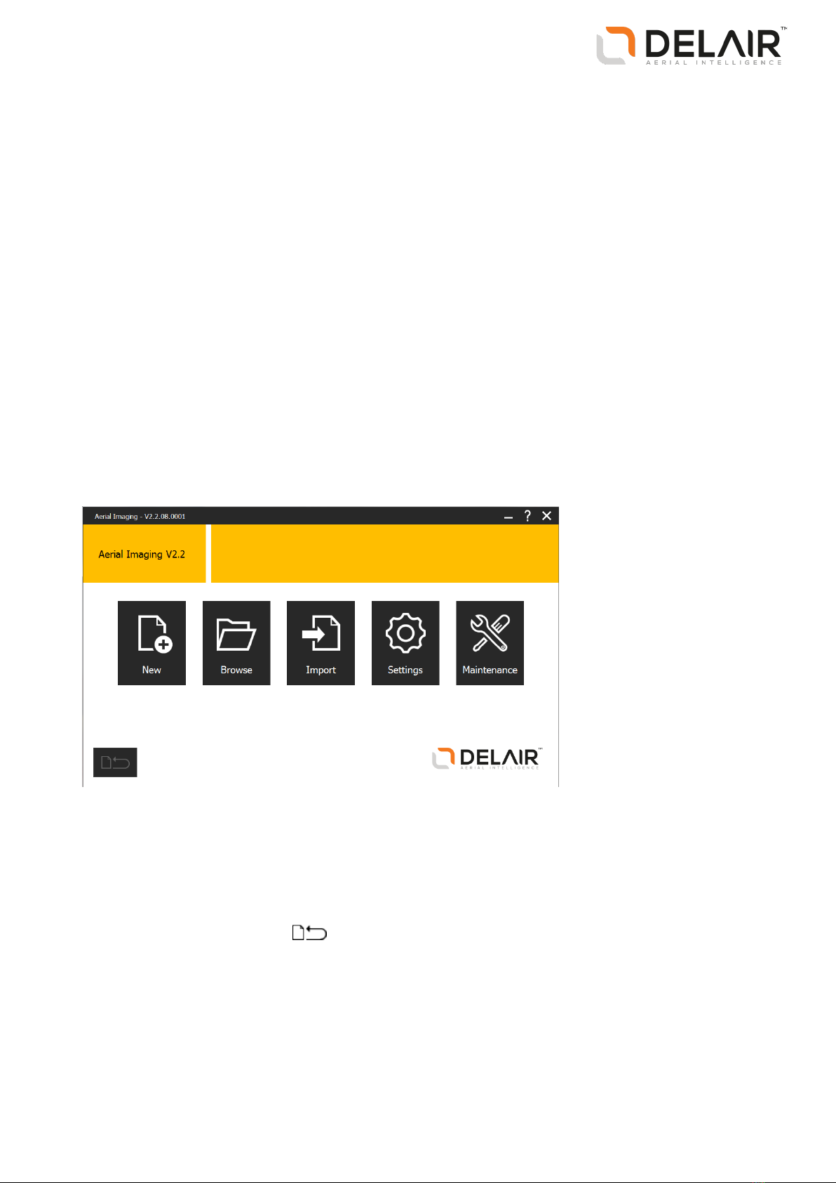
The Home screen
When you open the Aerial Imaging software, the Home screen appears.
The Home screen is shown below:
From this screen you can:
lCreate a new project or import a project. Alternatively, browse to the Projects screen to view available
projects. See The Projects screen, page 14.
lChange system settings. See Changing the system settings, page 16.
lAccess the Maintenance screen. See Performing maintenance, page 17.
To return to the current job, click .
13
Delair-Tech |676, Rue Max Planck – 31670 Toulouse-Labège, France |Tel: +33 (0) 5 82 95 44 06 |www.delair.aero
Capital: 238 110,30 € - APE: 3030Z – Intra-Community VAT number: FR90 53 09 69 781 – 530 969 781 R.C.S. Toulouse
This document is the sole property of Delair-Tech and cannot be used or reproduced without the written authorization of Delair-Tech.

The Projects screen
To view the Projects screen, click in the Home screen. Existing projects are displayed in the thumbnail
carousel on the left and in the list to the right.
To search for a project, enter the project name in the search bar above the list, or browse the project
thumbnails.
To change the order of projects listed, toggle the Sort by icon above the list:
Click... To list projects...
Alphabetically from A to Z
Reverse alphabetically from Z to A
Chronologically from earliest date modified to latest
Reverse chronologically from last date modified to earliest
To view project details, click beside the project name.
You must select a project before some of the buttons are enabled. You can do the following:
Click... To... For more information, see...
Create a new project. Creating a project, page 23
Import a project GWT file. Importing the project, page 70
Export the project GWT file. Exporting the project, page 45
Export a flight as a KML file or GPX file for
viewing the flight trajectory in software such as
Google Earth.
Exporting the flight trajectory for analysis,
page 101
Export project data as JXL or CSV/TXT files for
processing.
Exporting flight data for processing, page 100
Copy the project and all its content.
Open the project. The Map layers screen
appears.
Preparing the project map, page 24
Delete the project and associated flight data.
Software tabs
The Aerial Imaging software provides tabs that allow you to easily move between the different levels of
project information and phases of a project. When you open a project, the following tabs appear:
Tab Tab name Function
Map layers tab Define the background map and create
avoidance zones.
Blocks tab Define the area to aerially photograph and set
block properties, such as GSD and height.
Flights tab Add flights, and define flight properties, such
14
Delair-Tech |676, Rue Max Planck – 31670 Toulouse-Labège, France |Tel: +33 (0) 5 82 95 44 06 |www.delair.aero
Capital: 238 110,30 € - APE: 3030Z – Intra-Community VAT number: FR90 53 09 69 781 – 530 969 781 R.C.S. Toulouse
This document is the sole property of Delair-Tech and cannot be used or reproduced without the written authorization of Delair-Tech.

Tab Tab name Function
as the takeoff and landing locations.
Flight checklist tab Complete the flight checklist.
Dashboard tab Monitor the rover during flight.
Post-flight checklist tab Transfer the flight data from the rover to the
tablet.
Title bar buttons
The title bar of the software includes the following buttons:
Click... To...
Return to the Home screen.
Return to the Projects screen.
Show or hide the keyboard. If you are using the Aerial Imaging Desktop software, this button is
not displayed.
Save the project.
View the Aerial Imaging Help and the software About dialog.
Minimize the software screen.
Close the software.
Status icons
At the bottom of each screen, the footer shows the following information:
Icon Accompanying information Notes
GPS coordinates of the location of the cursor
on the map.
If you are using the Aerial Imaging Tablet
software, this icon is not displayed.
GPS coordinates of the location of the GCS. If the GCS has no GPS lock, the text "no GPS
lock" is displayed. If the GCS has issues with its
GPS hardware, the text "no GPShardware
detected" is displayed.
If you are using the Aerial Imaging Desktop
software, this icon is not displayed.
GPS coordinates of the location of the rover. If the rover has no GPS connection, this icon is
not displayed.
If you are using the Aerial Imaging Desktop
software, this icon is not displayed.
The battery level of the tablet. If you are using the Aerial Imaging Desktop
software, this icon is not displayed.
15
Delair-Tech |676, Rue Max Planck – 31670 Toulouse-Labège, France |Tel: +33 (0) 5 82 95 44 06 |www.delair.aero
Capital: 238 110,30 € - APE: 3030Z – Intra-Community VAT number: FR90 53 09 69 781 – 530 969 781 R.C.S. Toulouse
This document is the sole property of Delair-Tech and cannot be used or reproduced without the written authorization of Delair-Tech.

Icon Accompanying information Notes
The current local date and time (read from the
tablet).
If you are using the Aerial Imaging Desktop
software, this icon is not displayed.
Changing the system settings
To change settings for the Aerial Imaging software, click the Settings button in the Home screen.
After configuring the settings, do one of the following:
lClick to accept the settings.
lClick to discard the changes you have made to the settings and return to the Home screen.
General settings
Use the settings in the General group to specify:
lThe language used for the Aerial Imaging software.
If you change this setting, you are prompted to restart the Aerial Imaging software.
lThe source for online maps.
Note – Delair does not guarantee the accuracy of any mapping data source. It is your responsibility
to double-check the precision of the coordinates.
lThe status of Wi-Fi® and Bluetooth® wireless technology during fight. By default, Wi-Fi and Bluetooth
are turned off during flight.
lPreferred units for speed, distance, altitude, and area.
lThe delimiter for the CSV file, exported for processing.
Network settings
Use the settings in the Network group to specify the proxy settings for the Internet connection.
Select the check box to enable proxy settings for the Internet connection and then enter the settings to
use. If you change these settings, you are prompted to restart the Aerial Imaging software.
Note – You may need to configure the Internet proxy settings before you can view online maps. For the
correct settings to use, consult your network administrator.
External GNSS
(Available only when using the Aerial Imaging Tablet software.)
Use the settings in the External GNSS group to specify the communication interface on the tablet for an
external GNSS dongle.
The external GNSSdongle should:
lSupport the NMEA 0183 data protocol
lHave a serial port (such as USB)
16
Delair-Tech |676, Rue Max Planck – 31670 Toulouse-Labège, France |Tel: +33 (0) 5 82 95 44 06 |www.delair.aero
Capital: 238 110,30 € - APE: 3030Z – Intra-Community VAT number: FR90 53 09 69 781 – 530 969 781 R.C.S. Toulouse
This document is the sole property of Delair-Tech and cannot be used or reproduced without the written authorization of Delair-Tech.
Privacy
Select whether to allow user feedback gathering.
At Delair we believe that the data we collect should only be used to help us provide you with the highest
quality products, services, and support. Delair Aerial Imaging gathers information on how you use the
software and on which platform it runs. It does not store any IPaddresses, locations, or any other
individually identifiable data.
Performing maintenance
Check all equipment after each flight to ensure the equipment is in good working order. For more
information, see Preparing Equipment, page 49.
To perform maintenance on system components, click in the Home screen to view maintenance
procedures. If you note any issues not covered by the maintenance procedures, contact your Delair
distributor.
To exit the Maintenance screen and return to the Home screen, click in the title bar.
The following maintenance procedures are available:
lRover:
lReplacing the drive unit
lReplacing a servo
lReplacing a propeller blade
lReplacing the camera filter
lReplacing a winglet
lChecking the pitot tube
lReplacing the GNSSantenna
lReplacing the hot shoe cable
lCamera:
lAssembling the body and lens
lDisassembling the body and lens
lAdjusting the focus
lChecking the trigger and eBox feedback events
lLauncher:
lReplacing the launcher cord
lReplacing the wheels of the launcher dock
lCommunication:
lBinding the modem and eBox
lUnbinding the modem and eBox
lBinding the tracker transmitter and receiver
17
Delair-Tech |676, Rue Max Planck – 31670 Toulouse-Labège, France |Tel: +33 (0) 5 82 95 44 06 |www.delair.aero
Capital: 238 110,30 € - APE: 3030Z – Intra-Community VAT number: FR90 53 09 69 781 – 530 969 781 R.C.S. Toulouse
This document is the sole property of Delair-Tech and cannot be used or reproduced without the written authorization of Delair-Tech.

lFirmware:
lgBox:
lChecking the firmware version
lUpdating the firmware
leBox:
lChecking the firmware version
lUpdating the firmware
Note – Some maintenance procedures are only available in the Aerial Imaging Tablet software.
Updating the eBox firmware
The Aerial Imaging software automatically checks that the eBox firmware is up to date when the connection
between the GCS and the rover is established during the flight checklist procedure. If firmware updates are
available you are prompted to perform an update. It takes about 30 minutes to update the eBox firmware.
To manually initiate a firmware update, tap Updating the firmware in the Maintenance screen (see
Performing maintenance, page 17). To check the firmware version, tap Checking the firmware version in the
Maintenance screen.
1. When you are prompted to perform an update, do one of the following:
lTo dismiss the update checklist, tap . The flight checklist is aborted because the software does
not allow you to fly when the firmware version is not in sync with the Aerial Imaging software.
lTo start the firmware update, tap . The update checklist appears.
2. When prompted, attach the modem to the GCS. Tap to update the modem firmware.
3. When prompted, connect the download cable to the eBox and the modem. Tap to update the eBox
firmware.
4. The eBox firmware update consists of several automatic steps. When the firmware has finished
updating, disconnect the download cable from the eBox and the modem.
Depending on whether the Update firmware checklist was started automatically or manually, either
the start of the flight checklist or the Maintenance screen appears.
18
Delair-Tech |676, Rue Max Planck – 31670 Toulouse-Labège, France |Tel: +33 (0) 5 82 95 44 06 |www.delair.aero
Capital: 238 110,30 € - APE: 3030Z – Intra-Community VAT number: FR90 53 09 69 781 – 530 969 781 R.C.S. Toulouse
This document is the sole property of Delair-Tech and cannot be used or reproduced without the written authorization of Delair-Tech.

2 Planning a Project
nDesigning a flight plan to meet the project
requirements
nCreating a project
nPreparing the project map
nDefining the blocks
nObstacle clearances
nDefining the flights
nExporting the project
nChecking flight permissions and conditions
This chapter describes how to plan a project,
including preparing the project map, and creating
blocks and flights.
19
Delair-Tech |676, Rue Max Planck – 31670 Toulouse-Labège, France |Tel: +33 (0) 5 82 95 44 06 |www.delair.aero
Capital: 238 110,30 € - APE: 3030Z – Intra-Community VAT number: FR90 53 09 69 781 – 530 969 781 R.C.S. Toulouse
This document is the sole property of Delair-Tech and cannot be used or reproduced without the written authorization of Delair-Tech.

Designing a flight plan to meet the project requirements
There are many factors that can influence the success of a project. Good project planning is one of them.
A carefully planned project will ensure that flights are executed safely and that the captured data can be
processed successfully.
The quality of a project’s deliverable is often linked to its accuracy, referring to the positional accuracy of
the final output result. A project is processed based on geospatial coordinates, which are automatically
acquired during the flight. The output result has a relative accuracy of several times the GSD.
The GSD (ground sample distance) specifies the distance on the ground represented by the pixel of a
captured image. It depends on the camera sensor’s pixel size and lens focal length. The smaller the GSD
value, the more detailed the images. The GSD and the height at which the rover flies are linked. The higher
the rover flies, the larger the distance on the ground represented by each pixel in the images acquired
during the flight.
Other factors that impact the final output result include PPK, ground control points (GCPs), image overlap,
and camera settings.
If you need centimeter-level absolute accuracy, the rover should operate with PPK. PPK requires data from
a reference station. This station can be a local base station (with or without a precisely known position) that
you set up before the flight or a network reference station, such as CORS, that you access after the flight.
The absolute accuracy can be much improved by using ground control points (GCPs) if PPK is not available.
A ground control point is an accurately surveyed coordinate location for a physical feature that can be
identified on the ground. Use at least 5 GCPs, which are evenly spread over the area of interest.
The percentage of image overlap allows processing software to correct for errors in the position and
orientation of the aerial images (a rover is a dynamic platform with position and orientation sensors that
are not that precise). Delair recommends having a forward and sideward overlap of 80% which gives the
most accurate results while minimizing flight and processing time. There are some cases where increasing
the overlap may be beneficial. Examples are when flying over dense tree canopy, bodies of water, or large
areas of sand or snow. These often have a shortage of identifiable features in the images that can be used
as tie points for the image adjustment.
Image overlap also varies with changing terrain elevation and features. Use blocks at different heights to
ensure the same level of overlap for all areas of interest (see the images below). The image on the left does
not take into account the terrain elevation, which results in a varying amount of overlap. The image on the
right does take into account the terrain elevation, ensuring the same level of overlap for all areas of
interest.
20
Delair-Tech |676, Rue Max Planck – 31670 Toulouse-Labège, France |Tel: +33 (0) 5 82 95 44 06 |www.delair.aero
Capital: 238 110,30 € - APE: 3030Z – Intra-Community VAT number: FR90 53 09 69 781 – 530 969 781 R.C.S. Toulouse
This document is the sole property of Delair-Tech and cannot be used or reproduced without the written authorization of Delair-Tech.
Table of contents


