Hangzhou Qifei Intelligence Technology 3WD4-QF-10B User manual

User’s Manual
Q10Plant protection drone
Model: 3WD4-QF-10B
Q10Plant protection drone controller
Model: QF-T-1000
V 1.0.0
Hangzhou Qifei Intelligence Technology Co.,Ltd.

1
Table of Contents
1 Product Introduction.................................................................................................................................................9
1.1 Overview............................................................................................................................................................9
1.2 Features..............................................................................................................................................................9
2 Structures and software...........................................................................................................................................11
2.1 Aircraft.............................................................................................................................................................11
2.1.1 Product Dimensions..................................................................................................................................11
2.1.2 Structural Components..............................................................................................................................11
2.2 spray system.....................................................................................................................................................13
2.3 Remote Control and the GCS ..........................................................................................................................13
2.3.1 Appearance and components ....................................................................................................................13
2.3.2 Charger......................................................................................................................................................15
2.3.3APP interface.............................................................................................................................................15
3 Flight Preparation ...................................................................................................................................................18
3.1 preparation and inspection...............................................................................................................................18
3.1.1 remote control settings..............................................................................................................................18
3.1.2 Remote Control Calibration......................................................................................................................22
3.1.3 Accelerometer Calibration........................................................................................................................23
3.1.4 Magnetic Compass Calibration.................................................................................................................23
3.1.5 Setting Control Parameters .......................................................................................................................24
3.1.6 Voltage Reading and Setting.....................................................................................................................25
3.1.7 Setting crop protection Functions.............................................................................................................26
3.1.8 Setting flight parameters...........................................................................................................................26
3.1.9 Starting/stopping the motor.......................................................................................................................26
3.1.10 Motor Test...............................................................................................................................................27
3.2 Charge..............................................................................................................................................................28
3.2.1 Charge the Aircraft Battery.......................................................................................................................28
3.2.2 Charge the Remote Controller..................................................................................................................29
3.3 Prepare Aircraft................................................................................................................................................30
3.3.1 Unfold propeller........................................................................................................................................30
3.3.2 Install smart battery...................................................................................................................................30
4 Enable Flight...........................................................................................................................................................32
4.1 Overview..........................................................................................................................................................32
4.2 Manual Mode...................................................................................................................................................33
4.2.1 Flow Introduction of Manual Flight..........................................................................................................33
4.2.2 Unlock Flight Control...............................................................................................................................33
4.2.3 Manual Takeoff.........................................................................................................................................33
4.2.4 Manual Flight Control...............................................................................................................................34
4.2.5 Manual RTH and Landing........................................................................................................................35
4.2.6 Manual Lock.............................................................................................................................................35
4.3 Intelligent Mode...............................................................................................................................................36
4.3.1 Overview...................................................................................................................................................36
4.3.2 Intelligent Flight Mode.............................................................................................................................37
4.3.3A、B point operation mode......................................................................................................................42

2
4.3.4 Electric fence system ................................................................................................................................43
5 End Flight ...............................................................................................................................................................46
5.1 Cleaning after work .........................................................................................................................................46
5.2 Maintenance.....................................................................................................................................................46
6 Upgrade...................................................................................................................................................................47
7 Appendix I Specifications.........................................................................................................................................1
8 Appendix II Description ofAircraft Status Indicators..............................................................................................2
Legal Statement

3
Copyrights
© 2018 QiFei Intelligent Technology. All rights reserved.
Any or full contents of the user’s manual cannot be copied, transmitted, distributed, partially or wholly, by any
means, without the prior written notice of QiFei Intelligence Technology. (herein after “QiFei”).
QiFei or the third party may reserve the right of the product described in this user’s manual. Without the prior
written approval of the corresponding party, any person cannot (including but not limited to) copy, distribute,
amend, reverse compile, disassemble, engineering, rent, reverse engineer, reverse compile or disassemble the
software.
Trademark
are the trademarks or registered trademarks of the QiFei in various jurisdictions.
Other trademarks and registered trademarks mentioned are the properties of their respective owners.
Update and Modification
In order to enhance the product security and provide better user experience, QiFei may improve the product via
software auto update, but QiFei doesn't need to inform in advance and isn't liable to any responsibility.
QiFei reserves the right to modify any information in this document at any time, the modified contents will be
added into the new version without prior announcement. There may be minor difference about some product
functions after it is updated.
Preface

4
Document Overview
The document is to comprehensively introduce the product function features, structure parameters, installation
dismounting and flight guide etc.
Applied Model
Q10Plant protection drone
Model: 3WD4-QF-10B
Q10Plant protection drone controller
Model: QF-T-1000
Application Objective
The main readers of the manual are terminal users.
Reading Guide
Chapter
No.
Chapter
Name
Main Content
1
Product
Overview
It is to introduce the function features and application scenarios of the
product.
2
Product
Component
It is comprehensively to introduce the main components of the product.
It is recommended to read the chapter before use, which is to understand
the application methods of product structure and main components.
3
Flight
Preparation
It is to introduce the complete flow of aircraft unlock before takeoff in
details.
It has to strictly conform to the installation debudding sequence of the
chapter, install each component and make initial debugging before first
use.
If it is not the first time to use the device, you can select the installation
content according to the dismounting situation last time, but it has to be
confirmed that all the components (unnecessary steps excluded) listed in
the chapter have been stably installed.
4
Enable Flight
It is to introduce the complete flow of aircraft formal launch and landing
in details.
It has to complete the preparation steps listed in the chapter 3.
It needs to confirm that all the inspection items including environment
and the device itself have conformed to flight requirements before
enabling flight.
Please operate by strictly conforming to the steps described in the
chapter, the operation sequence can't be reversed.
5
End Flight
It is to introduce the operation steps after aircraft landing in details.
Please operate by strictly conforming to the steps described in this
chapter, the operation sequence can't be reversed.
6
Upgrade
It is to introduce upgrade methods and attentions.
7
Appendix 1
It is to introduce the technical parameters.
8
Appendix 2
It is to introduce the indicator definition of the aircraft.
5
Symbol Definition
The following symbol may appear in the document, please refer to the table below for the respective definition.
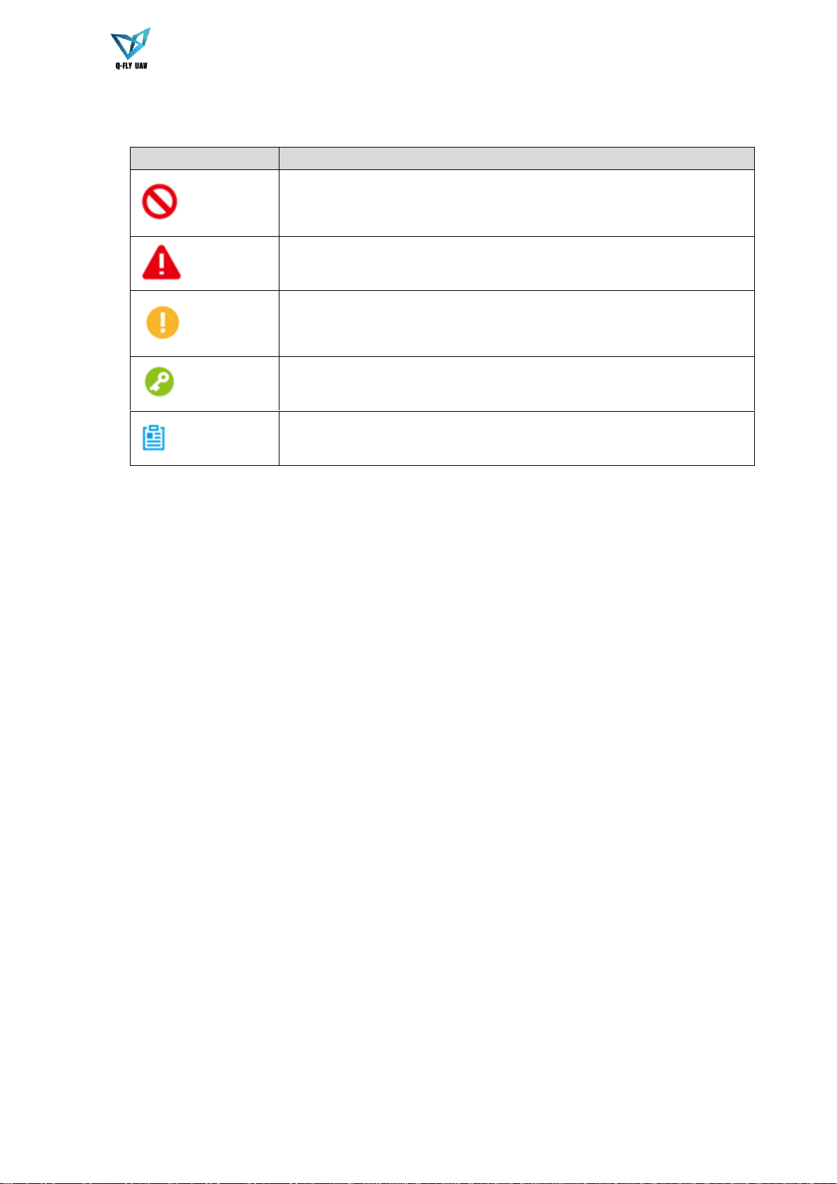
Symbol
Note
Danger
It means highly potential danger. It will cause severe injury or casualties if it
fails to avoid.
Warning
It means moderate or low potential danger. It may cause slight or moderate
injury if it fails to avoid.
Caution
It means potential risk. It may cause device damage, weaker performance or
other unpredictable consequences if it fails to avoid.
Tips
It means that it can help you to solve some problem or save your time.
Note
It means the additional information, which is the emphasis and supplement of
the main body.
Document Material
The product includes the following document materials, you can search according to your requirements:
<Quick Start Guide>
It can be applied to the first flight. Please refer to <User Manual> for operation details when it is used for the second
time or it has to use some other advanced functions.
Check the paper material affiliated in the packaging or log in www.qifeizn.com to acquire more details.
<User Manual> (the document it is)
It comprehensively introduces the product function features, structure parameters, installation dismounting and flight
guide etc.
Log in www.qifeizn.com and search 3WD4-QF-10B to acquire more details.

6
Important Safeguards and Warnings
The following description is the correct application method of the device. Please read the manually carefully before use
in order to prevent danger and property loss. It has to strictly conform to the manual during application and keep it
properly after reading.
Danger
Please fly the aircraft in an environment that meets the flight conditions, away from the no-fly zone.
Please do not touch the rotating parts to prevent injury.
The pesticide is toxic. Please use it with caution and operate according to the pesticide use specifications.
When using pesticides, please wear protective equipment to prevent direct contact with pesticides.After the
aircraft operation is completed, please clean the skin and clean the aircraft and remote control (wipe with a damp
cloth).
When using pesticides, it is strictly prohibited to pollute rivers and drinking water sources.
The use of highly toxic and special fluids is prohibited.
Warning
Please transport, use, and store the product and all other components in a compliant environment.
When disassembling the device, strictly follow the procedures described in the manual. Do not unduly remove
other components.
The use of 3WD4-QF-10BPlant protection drone has security risks and is not suitable for people under 18 years of
age.
Caution
Please operate the device by strictly conforming to the steps described in the chapter, the operation sequence can't
be reversed.
It needs to understand the local laws and regulations before using the aircraft. Please apply to local authorities for
flight permission if necessary.
Please select open wide environment outdoors for the first flight. It is to unlock the aircraft and take off when the
number of GPS satellites reaches more than 8.
Please make sure the device antenna has been properly installed before enabling the power of remote control,
ground station or aircraft, otherwise it may cause damage to internal module or make the control distance shorter.
When dispensing, please use clean water, it may cause the nozzle to be blocked. If there is any blockage during
use, please clean it up before use.
Avoid using powder pesticides, it may affect the service life of the spraying system.
Flight Environment
Warning
Please make flight in the environment which meets the following conditions:

7
Keep away from no-fly zone, please do not enter no-fly zone.
Maximum flight radius: 1 km.
Please do not fly the aircraft in rain, snow and thunder weather.
Please do not fly in narrow and small space.
Do not fly above the crowd to avoid personal injury or poisoning.
Please do not get close to high-voltage power line.
Power Requirements
Caution
Please strictly conform to your local electrical safety codes.
Make sure the power supply is correct before operating the device.
The power source shall conform to the requirement of the Safety Extra Low Voltage (SELV) standard, and supply
power with rated voltage according to the Limited Power Source requirement of IEC60950-1. Please note that the
power supply requirement is subject to the device label.
Prevent the power cable from being trampled or pressed, especially the plug, power socket and the junction
extruded from the device.
Battery Attentions
Warning
It has to use the exclusive power adapter to charge the device provided by QiFei, otherwise it may cause damage
to the battery or other unpredictable consequences.
It has to charge the device at a temperature which is between 0 and 50℃.
It has to distinguish positive and negative when charging the device, which is to prevent short circuit.
Please do not place the device close to fire source or inflammables.
Please do not charge and discharge the device in a situation where it is not guarded by people.
Please do no use undesignated battery to the device.
Please do not dismantle and destroy the battery without permission, water is not allowed to enter the device,
damages caused by human is not covered by warranty.
Please do not throw the battery into fire or make it exposed to the environment with high temperature.
Please do not dismantle or modify the battery, or make the battery transformed.
Avoid contact short circuit between positive and negative (Please do not place the battery together with the objects
such as necklace and hairpin etc. when carrying or storing the battery).
Please replace new battery in time when it is damaged.
Please charge the battery or discharge it to 30%~40% of remaining battery if it won't be used for a long time, and
place it in a dry and cool environment.
If the battery leaks and the liquid enters eyes accidentally, please do not rub your eyes, you should wash your eyes
with clean water and see a doctor immediately.
Caution
It is normal the battery heats up after it is running for a period of time, because the discharge power is quite big.
It is normal the battery heats up when it is being charged.

8
The cycle times of power battery is 300 in normal application situation.
Application Environment Requirements
Please transport, use and store the device in the allowed humidity and temperature range.
Please do not let any liquid flow into the device.
Please do not vibrate or soak the device.
Please pack the device with default package or material with equivalent quality.
Operation and Maintenance Requirements
Warning
Please do not dismantle the device unprofessionally.
Please use soft dry cloth or use clean soft cloth and dip a little mild detergent to clean the device.
Please use the accessories provided by manufacturer and it shall be installed and repaired by professional staff.
Disclaimer
This manual is for reference only. Please refer to the actual product for more details.
Minor differences might be found in user interface, and there might be deviation between the actual value of some
data and the value provided in the manual due to the reasons such as the real environment is not stable. Please
refer to the final explanation of the company if there is any doubt or dispute.
All the designs and software are subject to change without prior written notice. The manual will be regularly
updated according to the product upgrade without prior announcement.
Please contact the supplier or customer service if there is any problem occurred when using the device.
Other trademarks and registered trademarks mentioned in the document are the properties of their respective
owners.
Please use this product within the scope allowed by local laws. Qifei shall not be liable for any illegal use.
This product belongs to a low-level crop protection UAS. Please strictly abide by the relevant product's
operating specifications. Hangzhou Qifei Intelligence Technology Co., Ltd. shall not be responsible for any
performance, safety and legal liability caused by any operation and usage control.
Please fly under the guidance of professionals. Install and use this product according to this manual. Qifei is
not responsible for accidents caused by improper installation, configuration, operation, etc.

9
1Product Introduction
1.1Overview
The series is a four-axis unmanned aerial vehicle (UAV). It is designed for agriculture and forest areas. Drones are
mainly divided into Two modes: automatic and manual flight mode.
The product consists of flight platforms, spray systems, remote controls and ground control stations (GCS).
Flight platform: It consists of navigation system, flight control system and power system.
Spray system: Spray control system, pump, pipeline, medicine box, nozzle and other components.
Remote control: It consists of a remote controller and a digital radio station.
GCS: Composed of aAndroid smart phone andAPP software.
1.2Features
Integrated Design
The propeller adopts a folded structure. No need to install a propeller before takeoff.
The remote control integrates a mobile phone, a digital radio station, which is easy to operate.
The pesticide tank is fixed on the body and is not disassembled.
Accurately Positioning
GPS accuracy: 1.5m
Terrain Following Function
Millimeter-wave radar
Wireless Transmission
The aircraft has several antennas. They are used for: remote control receiver, communication with ground
station and GPS antenna, RTK spiral antenna (only RTK version includes this component).
Low Battery Level Protection
When the low battery level triggers the aircraft to return to home, it can trigger low battery level protection
such as alarm, return to home and landing.
Flight Log
The ground station automatically records the flight record logs.
Intelligent Battery
Anti-shock and wear-resistant housing to extend battery life.
LED automatic power display.
Charging smart alarm to prevent overvoltage, overcurrent, and high temperature damage to the battery and
eliminate potential safety hazards.
Low-voltage smart alarm (buzzer).
When the battery is not used for a long time, it will automatically discharge to the storage voltage, extending
the battery life.
Logging function.
Automatic shutdown function.If it is not used for more than 3 minutes, the battery will automatically shut
down to save power.

10
Parameter specifications:
Output voltage: 39.6 ~ 50.4 V Nominal voltage: 44.4V
Charging voltage: 50.4V Battery weight: 4.40kg
Charge Current: MAX 24A (1.5C) Nominal Capacity: 16000mA
Flight Control
The aircraft adopts a four-axis structure and has multiple control modes,which is simple and safe.
Maximum taking off weight 28.5kg.
Electronic Fence
Support electronic fence (e-fence) function in case the aircraft is out of the specified flight zone.
Support customized e-fence settings.
Battery alert
LED1
LED2
LED3
LED4
Current power
○
○
○
○
0%-8%
●
○
○
○
8%-25%
●
○
○
○
25%-37.5%
●
●
○
○
37.5%-50%
●
●
○
○
50%-62.5%
●
●
●
○
62%-75%
●
●
●
○
75%-92%
●
●
●
●
92%-100%

11
2Structures and software
This series product includes aircraft, sprinkler systems, remote control, and ground control station (GCS).
This chapter introduces the structures of these four components and the software used for ground stations. The
detailed operations will be introduced in chapter 3.
Note
All figures listed below and all dimensions listed here for reference only. The figure and the dimensions may be
slightly different from the user data due to measure position, measure accuracy, and position indicator. Please refer
to the actual product for detailed information.
2.1Aircraft
For detailed operation please refer to Chapter 3
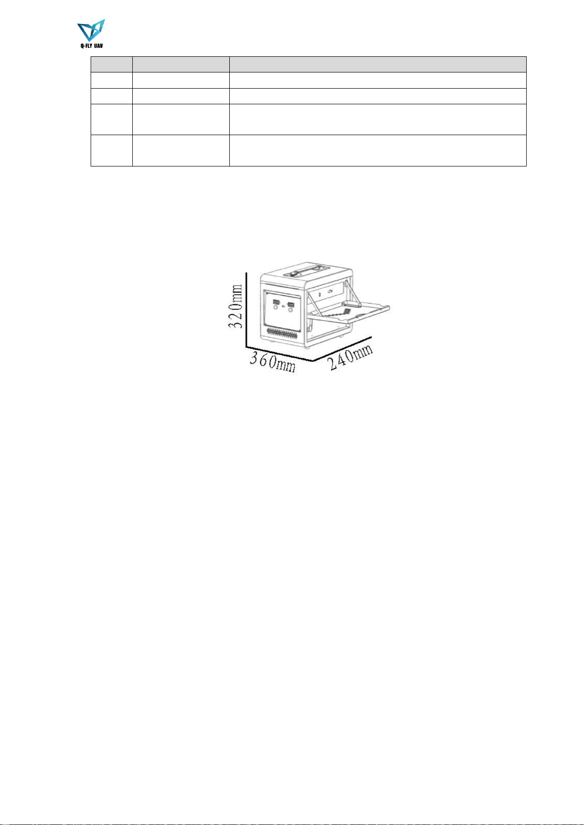
2.1.1 Product Dimensions
The aircraft is shown as in Figure 2-1.
Figure 2-1
2.1.2 Structural Components
The structure of the aircraft is shown as in Figure 2-2.

12
Figure 2-2
For details, please refer to the following table.
No.
Name
description
1
propeller
High-speed rotation provides lift,folding paddles to save space.
2
Motor
Drive propeller rotation.
3
Sprinkler pipe
Connecting pesticide pipes and nozzles.
4
nozzle
Spray and atomized pesticides.
5
Direction indicator
Indicate the direction.
6
Arm
Non-folding arm with higher strength, stronger and durable.
7
Pesticide tank
As a container for pesticides, volume: 10L.
8
radar
detect height and follow terrain.
9
Entrance for pesticide
loading
Entrance for pesticide loading.
10
Landing gear cushion
Reduce shock when landing.
11
landing gear
Support the aircraft.
12
LED flight status
indicator
Indicate the status of each flight. For details, please refer to the
appendix Instructions for indicating the status of the aircraft.
13
Battery retention hook
To fix the battery
14
Battery installation
position
Where to install the battery
15
Aircraft shell
Protect internal components
16
Pump
pumping pesticides.

13
No.
Name
description
17
Pesticide delivery
pipeline
Transport pesticides
18
pesticide outlet connector
Connection of the pump and the pipe.
19
Flow Meter
Measure real-time flow data and feed back to the sprinkler system
20
Night light
Illumination at night
21
GPS
Positioning
22
Aircraft body
Support the overall structure of the aircraft
2.2spray system
3WD4-QF-10BPlant protection drone spray system adopts 12V diaphragm pump and Y-type pressure
spraying, which can achieve forward and backward switchable spraying. During operation, parameters such as
spray flow rate, spray width, and flight speed can be adjusted based on actual operating conditions.
Spraying flow: 1600-2000 ml/min.
Spray width: 1-20 meters (depending on flight altitude).
Flow meter: Real-time monitoring of the spray system (such as: flow , flow rate, remaining amount of
pesticide, etc.), automatic return or hovering when the drug is broken.
See Figure 2-2 for details.
2.3 T1000 Remote Control and the GCS
2.3.1 Appearance and components
The remote control T1000 is shown as below. See Figure 2-3 ,Figure 2-4,Figure 2-5.
Figure 2-3

14
Figure 2-4
Figure 2-5
For details, please refer to the following table.
No.
Name
description
1
Remote control
antenna
Communicate with aircraft
2
Phone bracket hole
The hole used to install the phone holder
3
Left stick
The default left stick's Y axis is channel 3 (THRO) and X axis is
channel 4 (YAW).
4
Right stick
The default right stick's X axis is channel 1 (ROLL) and theY axis is
channel 2 (PITCH).
5
Power switch
Power switch of the remote control.
6
One-click return key
It defaults to channel 6 (return).
7
work indicator
It defaults to red
8
Power indicator
Display the power of the remote control.
9
Mode switch
It is also called a three-state switch and defaults to channel 5
(MODE)
10
Left wheel
Not Enabled
11
Right wheel
The switch is used to record the A, B points
12
Channel 9
Not Enabled
15
No.
Name
description
13
Channel 10
Pump switch
14
Channel 11
Not Enabled
15
Micro USB Socket
It is used to connect the phone. Remote control software can be used
to adjust the mode.
16
USB TYPE C
Socket
It is used to connect the phone,and communicate with your smart
phone.
2.3.2 Charger
The shape and size of the charger are shown in Figure 2-6.
Figure 2-6
Product parameters
1. Input voltage: AC 190 ~ 220V
2. Maximum charging current: Channel CH1: 20.0A; Channel CH2: 20.0A
3.Average output voltage: Channel CH1: 50.4V; Channel CH2: 50.4V
4. Maximum balanced current: 400mA
5. Maximum static power consumption: 320mA
6. Display mode: LED display
7. Support battery type: 12S
8. Working environment temperature: 0 ~ 40°C
9. Weight: 12KG
2.3.3 APPinterface
Advantages: simple operation, high degree of intelligence (voice broadcast the real-time data of each
module ), complete functions.
2.3.3.1 Flight data interface
This screen shows the aircraft's flight status and basic flight operation buttons. At the top , the icons from left
to right are flight mode, battery voltage value, GPS star number (satellite display), connection status (all sensors
are displayed abnormally), remote control signal (connection will turn green), data link status(the connection will
turn green), parameter settings. On the left side, From top to bottom there are take-off button, return flight button,
route planning function button and human/aircraft positioning button. The upper right side is the status information
bar, and the two buttons at lower right are the map type switching button and the map rotation button. See Figure

16
2-7 and Figure 2-8.
Figure 2-7
Figure 2-8
2.3.3.2 Description of the top menu bar
Flight Mode: Displays the flight mode of the current aircraft.
Battery voltage value: Displays the current battery level.
Satellite display: Displays the current number of searched stars for flight control.
Connection Status: Displays the status of all sensors connected to the flight controller. The icon
turns green when the connection is normal.
Remote control signal: Displays the remote control signal status.
Digital Radio Link: Shows the connection status of the data link. After the connection is normal, the
icon will turn green.
17
Parameter settings: Click to set the relevant parameters of the flight control.
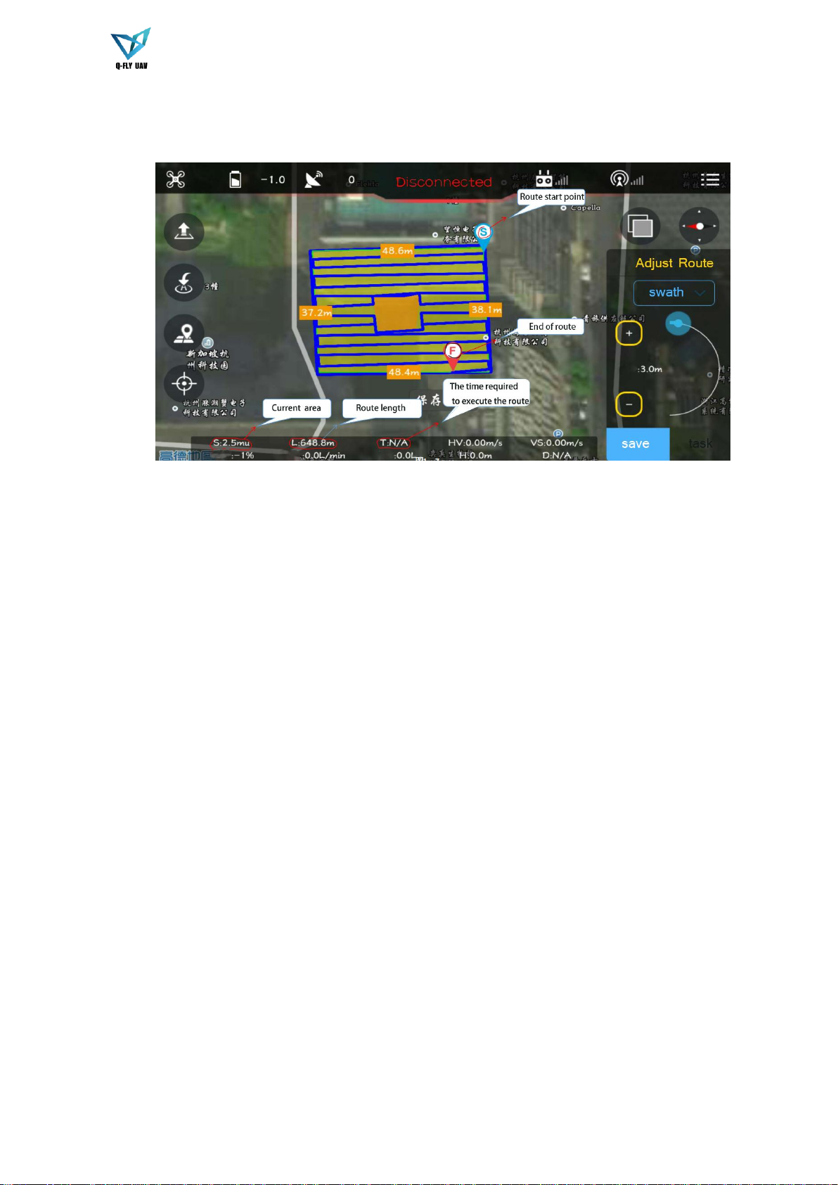
2.3.3.3 Route planning interface
Figure 2-9
18
3Flight Preparation
Note
The following chapter is going to introduce complete flow in details before the aircraft unlocked and takes off.
Please select operation according to the actual situation after the first flight is over if it is not the used for the
first time.
Caution
Please operate by strictly conforming to the steps described in this chapter; the operation sequence can't be
reversed.
3.1preparation and inspection
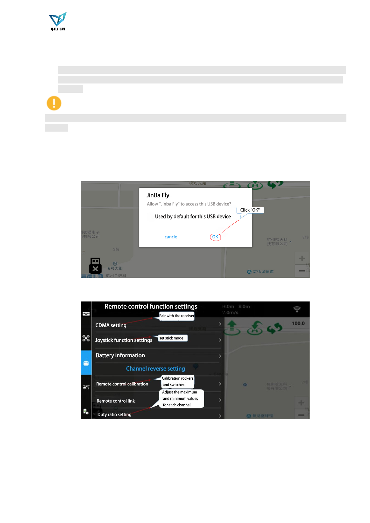
3.1.1 T1000 remote control settings
There are 6 steps (as shown in Figure 3-1 to Figure 3-11):
Figure 3-1
Figure 3-2

19
Figure 3-3
Figure 3-4
Figure 3-5
Table of contents
Other Hangzhou Qifei Intelligence Technology Drone manuals


