DeLaRue MACH 12 User manual
u
uu
us
ss
se
ee
er
rr
rg
gg
gu
uu
ui
ii
id
dd
de
ee
e
M
MM
MA
AA
AC
CC
CH
HH
H1
11
12
22
2
Coin Sorter and Counter
MICS Control w/RS232 Interface


i
DE LA RUE
CASH SYSTEMS INC.
Box 200
705 S. 12th Street
Watertown, WI 53094 USA
Tel: ( 920 ) 262--3300 ( Sales )
( 800 ) 527--2638 ( Supplies )
Fax: ( 920 ) 261--1783 ( Sales )
( 920 ) 262--3374 ( Supplies )
Web: http://www.delarue.com
De La Rue
Cash Systems Inc.
a division of
De La Rue International Ltd.
Registered Office
Box 200
705 S. 12th Street
Watertown, WI 53094 USA
Dear Customer,
Thank you for purchasing the Mach 12 Coin Sorter/Counter from De La Rue. This product is yet
another step to fulfilling our mission:
To enable the secure and cost effective availability of cash
when and where people need it.
This innovative product incorporates the very latest technology for you to process coins faster
and more accurately than ever before. It contains De La Rue designed and patented components
which make this product unique.
Additional benefits of the Mach 12 are:
SOne of the fastest Coin Sorters available, sorting coins at speeds of up to 4500 per minute
SCapable of sorting up to nine denominations of coin
SAutofeed system improves throughput
SFew moving parts and simplified electronics, making it easy to use and maintain
With over 100 years’ experience in the design, development and manufacture of world class coin
processors, De La Rue supplies more products world-wide than any other manufacturer. Quality
is paramount in our manufacturing process, and we are proud to hold certificates for European
Quality Directives for both safety and electromagnetic standards. In addition to this,
manufacturing sites have been awarded ISO9001 quality certificates.
To ensure maximum life from your Sorter, we recommend that it is regularly serviced. To assist
you, we provide worldwide service and support through our network of branch offices and
authorized distributors. Please contact them for the location of your nearest service office.
We wish you many years of carefree Mach 12 use.
De La Rue
Cash Systems Inc.

ii
FCC Interference Statement
Warning
This equipment generates, uses and can radiate radio frequency energy and if not installed and used in
accordance with the instruction manual may cause interference to radio and television reception. It has
been tested and found to comply with the limits for a Class A or Class B computing device pursuant to
Subpart J of Part 15 of FCC Rules which are designed to provide reasonable protection against such
interference in a residential installation. However, there is no guarantee that interference will not occur
in a particular installation. If this equipment does cause interference with radio or television reception,
which can be determined by turning the equipment off and on, the user is encouraged to try to correct
the interference by taking one or more of the following measures:
nReorient the receiving (radio/TV) antenna
nMove the sorter to the right or left with respect to the receiver
nMove the sorter away from the receiver
nPlug the sorter into a different outlet so that the sorter and receiver are on different branch circuits.
Warning: Only equipment certified to comply with the Class A or Class B limits may be attached.
Operation with noncertified equipment is likely to cause radio and TV reception interference.
Peripherals should be interfaced using only shielded cables to maintain FCC Class A or Class B certifi-
cation and to reduce the possibility of interference with radio and television reception.
Reference material
If this equipment does cause reception interference, the user should contact an authorized sales or
service representative for suggestions. Two booklets, the CIB Interference Handbook and the CIB Tele-
phone Interference Booklet are provided by the Compliance and Information Bureau of the Federal
Communications Commission. To obtain copies, call the Bureau at (202) 418-1100 or on the Internet at
http://www.fcc.gov/cib.
De La Rue International Limited is pleased to give detailed specifications of its products in this manual
but expressly reserves the right to vary these at its discretion at any time without notice. As the Compa-
ny’s products and services are continuously being developed it is important for customers to check that
the information herein includes the latest particulars. This guide is for general guidance only and may
contain inappropriate information under particular conditions of use. All recommendations and sugges-
tions issued by or on behalf of the Company in whatever form, are subject to the Company’s terms and
conditions of sale, of which a copy will be supplied on request. This document is not part of a contract
or license, save insofar as may be expressly agreed.
De La Rue International Limited 1997
All items of technical information, advice, knowhow, drawings, designs, specifications and other items
communicated in this document are confidential and remain the property of De La Rue International
Limited and shall not be disclosed to a third party without written consent of De La Rue International
Limited.
The above duty of confidence also entails a prohibition of reproduction of this text without authority, in
writing from De La Rue International Limited.

iii
user guide
MACH 12
Coin Sorter and Counter
MICS Control
w/RS232 Interface
The information contained herein is proprietary
and is not to be used for purposes other than
as an aid in the operation and/or maintenance
of the equipment described herein and is fur-
ther not to be released or reproduced by any-
one without the written permission of:
DE LA RUE
CASH SYSTEMS INC.
BOX 200
705 SOUTH 12TH STREET
WATERTOWN, WISCONSIN 53094
USA
#0000605 COPYRIGHT 2000 Printed
REV 04 ALL RIGHTS RESERVED in USA
SAFE OPERATION OF THIS PRODUCT IS DEPENDENT UPON PROPER
INSTALLATION WITH COMPATIBLE EQUIPMENT AND BY AN AUTHORIZED SALES
OR SERVICE REPRESENTATIVE. INCOMPLETE OR INCORRECT INSTALLATION
MAY RESULT IN DAMAGE TO THE EQUIPMENT OR PERSONAL INJURY.
ACCIDENTS AND COUNTING INACCURACIES CAN BE AVOIDED IF THE
OPERATOR IS COMPLETELY FAMILIAR WITH THIS PRODUCT AND ITS
OPERATION. ONLY COINS / TOKENS WITHIN THE RANGES DESCRIBED IN THE
SPECIFICATIONS SECTION OF THIS GUIDE SHOULD BE PROCESSED. ANY / ALL
OTHER OBJECTS SHOULD BE REMOVED FROM THE COIN MIX BEFORE
PROCESSING. NEVER ALLOW TOOLS, FINGERS, HAIR OR LOOSE CLOTHING
NEAR MOVING PARTS. NO ATTEMPT SHOULD BE MADE TO DISASSEMBLE THIS
PRODUCT. IF SERVICE IS REQUIRED, CONTACT YOUR AUTHORIZED SERVICE
REPRESENTATIVE.
THIS IS NOT A
SELF--SERVICE PRODUCT.
OPERATION OF THIS PRODUCT
SHOULD BE PERFORMED ONLY
BY PROPERLY TRAINED
PERSONS.
DELARUE ACCEPTS NO LIABILITY FOR
ANY LOSS OR DAMAGE ARISING OUT OF
THE UNAUTHORIZED USE, MODIFICATION
OR ADJUSTMENT OF THE PRODUCT OR
RELATED EQUIPMENT DESCRIBED OR
REFERRED TO IN THIS DOCUMENT.
iv
Declaration of conformity
Manufacturer & responsible person Details of product
DE LA RUE Coin Sorter / Counter
CASH SYSTEMS INC.
Box 200
705 S. 12th Street Model types
Watertown, WI 53094 USA
Telephone: (920) 262 - 3300 6400000 -- 6499999 (230V)
Fax: (920) 261 - 1783
This product conforms to the essential requirements of:
Directive 89 / 336 / EEC Electromagnetic compatibility
Directive 73 / 23 / EEC Low voltage electrical equipment (safety)
and conformity has been demonstrated by meeting the applicable requirements of the
following standards:
user guide

v
contents
1. INTRODUCTION 1....................
2. MODEL IDENTIFICATION 2............
3. SPECIFICATIONS 3...................
4. OPTIONS 4..........................
5. INSTALLATION
UNPACK 5...........................
COIN BAGS / POWER CORD 6.........
POWER / INTERLOCK SWITCHES 7....
PRINTER PAPER 8....................
6. OPERATOR CONTROL MODULE
OVERVIEW 9.........................
FUNCTION KEYS 10..................
ICONS 11.............................
DISPLAY SCREENS
HOME 16............................
HOME ALL CLEAR 17.................
FULL BAG DISPLAY 18................
ID ENTRY 19.........................
VIEW ID 20...........................
SUB ID TOTALS 21....................
GRANDIDTOTALS 22.................
MEDIA 23............................
NOTE (CURRENCY) ENTRY 24.........
BAGSTOP ENTRY 25..................
BATCH HEADER SUMMARY 26.........
BATCHCOINSUMMARY 27............
BATCH NOTE (CURRENCY)
SUMMARY 28........................
SUB HEADER SUMMARY 29...........
SUB COIN SUMMARY 30..............

vi
contents
6. OPERATOR CONTROL MODULE (CON’T)
SUB NOTE (CURRENCY) SUMMARY 31.
GRAND HEADER SUMMARY 32........
GRAND COIN SUMMARY 33...........
GRAND NOTE (CURRENCY)
SUMMARY 34........................
BAG COUNT DISPLAY 35..............
7. OPERATING THE SORTER
APPLYING POWER 36.................
SETTING TIME / DATE 37..............
PROCESSING COIN 43................
DISPLAYING QUANTITIES
AND / OR TOTALS 45..................
ACCEPTING QUANTITIES
AND / OR TOTALS 56..................
CLEARING QUANTITIES
AND / OR TOTALS 57..................
WHEN YOU REACH A BAGSTOP 59....
CHANGING THE BAGSTOP
QUANTITY 60........................
CHANGING THE NUMBER OF
BAGSTOPS 62.......................
BAGSTOP ENTRY ERROR 63..........
OPERATOR DATA ENTRY
BATCHIDENTRY 64..................
INDIVIDUAL ID VIEWING 65............
SUB ID ENTRY / VIEWING 66...........
GRANDIDENTRY/VIEWING 68........
PRODUCT (ID NUMBER) TOTALS 70....
ID NUMBER EXAMPLE 71..............
ENTERING PARTIAL BAG COUNTS 76..
MEDIA ENTRIES 78...................
MEDIA ENTRY ERROR 80.............

vii
contents
7. OPERATING THE SORTER (CON’T)
THE FEE FUNCTION 81...............
THE CURRENCY INPUT FUNCTION 87..
OPERATION W / CURRENCY
COUNTER INPUT 88..................
FOR “BRANDT” NOTE (CURRENCY)
COUNTERS 89.......................
OPERATION (W/MODEL 2800) 91.......
ERRORS / BAGSTOPS 93..............
8. OPERATOR DISPLAY MESSAGES
INTRODUCTION 94...................
COVER OPEN / COIN JAM 94..........
RAM / ROM ERROR 95................
ILLEGAL KEY OR CLEAR SEQUENCE 96
CLEAN SENSOR 97...................
COIN BAG PRESENCE 98.............
NO ACCEPT WHILE COUNTING 99.....
PRINTER BUSY 100...................
COMMUNICATIONS ERROR 101........
ID ENTRY ERROR 102.................
DUAL BAG DIVERTER ERROR 103.....
9. PROGRAMMING
ICONS 105...........................
DEFAULT SETTINGS 107..............
INITIALIZING CONTROL FOR
INTERNAL PRINTER OPERATION 110...
INITIALIZING CONTROL FOR
EXTERNAL PRINTER OPERATION 114..
INITIALIZING CONTROL FOR
REMOTE DISPLAY OPERATION 117....
PROGRAMMING KEY FUNCTIONS 120..
10.CIRCUIT PROTECTION 153............
11. SORTER CLEANING / JAM REMOVAL154
12.SERVICE 158.........................

viii

1
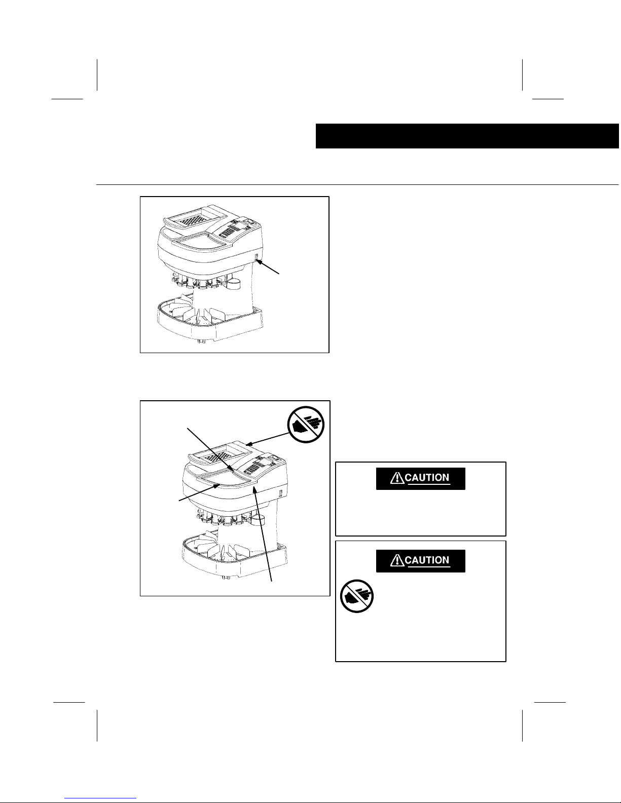
overview
Introduction
The Mach 12 Coin Sorter and Counter is de-
signed for ease of operation. Coins are sorted
and counted at a rate of up to 6,000 coins per
minute (depending on the coin mix). Both the
denomination and quantity totals are registered
on the Operator Control Module located on the
front of the Sorter.
1. Inspection Pan
Allows inspection of coin mix and removal of
unwanted objects before coins enter the
Sorting Area.
2. Power Switch
Turns Main Power to Sorter on and off.
3. Operator Control Module
Communications link between the Sorter
and the operator. All Sorter operation is
controlled here.
4. Display
Visual communications link between the
Sorter and the Operator.
5. Keylock
Allows access to programming mode.
6. Access Cover (Work Surface)
Convenient work space for operator.
Note: Remove to raise Top Housing for ac-
cess to Sorting Module and / or other inter-
nal components.
1
6
2
4
3
5
FIGURE #1
SORTER DESCRIPTION

2
model identification
Model identification
6420042 USA / CANADA -- W / O PNTR
6420052 USA / CANADA -- W / PNTR
6400062 USA CASINO -- W / O PNTR
6400072 USA CASINO -- W / PNTR
6400082 USA DUAL/DUAL -- W / O PNTR
6400092 USA DUAL/DUAL -- W / PNTR
6400102 USA (.800 TKN) -- W / PNTR
6400105 USA (2 TKN) -- W / PNTR
6400113 UK -- W / O PNTR
6400114 UK -- W / PNTR
6400118 FRANCE -- W / O PNTR
6400119 FRANCE -- W / PNTR
6400123 SPAIN -- W / O PNTR
6400124 SPAIN -- W / PNTR
6400128 AUSTRALIA -- W / O PNTR
6400129 AUSTRALIA -- W / PNTR
6400130 IRELAND -- W / PNTR
6400133 IRELAND -- W / O PNTR
6400134 IRELAND -- W / PNTR
6400135 IRELAND -- W / O PNTR
6400138 NEW ZEALAND -- W / O PNTR
6400139 NEW ZEALAND -- W / PNTR
6400140 USA (C--MECH) -- W / PNTR
6400143 MEXICO -- W / O PNTR
6400144 MEXICO -- W / PNTR
6400148 GERMANY -- W / O PNTR
6400149 GERMANY -- W / PNTR
6400153 NETHERLANDS -- W / O PNTR
6400154 NETHERLANDS -- W / PNTR
6400155 POLAND -- W / PNTR
6400158 POLAND -- W / O PNTR
6400159 SOUTH AFRICA -- W / PNTR
6400163 ITALY W / O PNTR
6400164 ITALY -- W / PNTR
6400166 IRELAND -- W / PNTR
6400169 USA (.784” TKN) -- W / PNTR
6400173 BELGIUM W / O PNTR
6400174 BELGIUM -- W / PNTR
6400177 UAE -- W / O PRINTER
6400178 UAE -- W / PRINTER
6400180 GREECE -- W / O PRINTER
6400181 GREECE -- W / PRINTER
6400200 USA
DL .05 / DL .25 -- W / O PNTR
6400220 USA
(.900/1.125 TKN) -- W / PNTR
6400230 USA / CANADA
(.650/.800/.900T) W / O PNTR
6400242 USA DUAL .25 -- W / O PNTR
6400252 USA DUAL .25 -- W / PNTR
6400262 CANADA
QUAD DUAL -- W / PNTR
6400266 CANADA (1.00 T)-- W / PNTR
6400272 USA
.984T/D25/D$1 -- W / PNTR
6400282 USA
DL .01 / DL .25 -- W / PNTR
6400352 USA 4 DUAL -- W / PNTR
6400452 USA
DL .05 / DL .25 -- W / O PNTR
6400540 USA CASINO
3 TOKEN -- W / O PNTR
6400640 USA
(COIN MECH) -- W / PNTR
6400660 USA
DL .25 / .984” T -- W / PNTR
6400740 USA
DL .01 / DL .25 -- W / PNTR
6420160 SOUTH ARFICA -- W / PNTR
6400801 EURO ( A ) -- W / O PNTR
6400802 EURO ( A ) -- W / PNTR
6400803 EURO ( A ) -- W / O PNTR
6400804 EURO ( A ) -- W / PNTR
6400805 EURO ( B ) -- W / O PNTR
6400806 EURO ( B ) -- W / PNTR
6400807 EURO ( B ) -- W / O PNTR
6400808 EURO ( B ) -- W / PNTR
6400809 IRELAND ( A ) -- W / PNTR
6400810 IRELAND ( A ) -- W / PNTR
A = FINLAND, FRANCE, GERMANY, GREECE, IRELAND, ITALY, PORTUGAL, SPAIN
B = BELGIUM, AUSTRIA, LUXEMBOURG, NETHERLANDS

3
specifications
Specifications
Size; Height 40 Inches (102 cm)...........
Width 27 Inches (69 cm)............
Depth 28.25 Inches (72 cm)...........
Weight 200 Pounds (90 kg)...........
Sorting Speed Up to 6,000 Coins per Minute....
(depending on coin mix)
Ambient (Room) Temperature +77 Degrees Fahrenheit.........
+25 Degrees Centigrade
Voltage Compatible with most worldwide..........
voltages and frequencies.
100 -- 240 VAC / 50 or 60 HZ, 6.3A
Coin Diameter Capability .640” (16.26 mm) Dia. (Min.).............
1.467” (37.26 mm) Dia. (Max.)
Coin Thickness Capability .039” (1 mm) (Minimum)............
.118” (3 mm) (Maximum)
Inspection Pan Capacity Approximately 5,000 Coins.............
(18 mm) Dia.
Hopper Capacity Approximately 5,000 Coins....................
(18 mm) Dia.
* Weight is approximate, will vary with options selected.
THIS EQUIPMENT MUST BE GROUNDED FOR PROPER OPERATION. USE OF EXTENSION
CORDS OR 3--2 ADAPTERS IS NOT RECOMMENDED. IF A 3--2 ADAPTER IS USED, THE
GROUNDING WIRE OR TANG MUST BE CONNECTED TO THE BUILDING GROUND. FOR
OPTIMUM SAFETY, THE POWER CORD SHOULD BE DISCONNECTED FROM THE POWER
SOURCE BEFORE CLEANING OR SERVICING. THE SOCKET OR OUTLET SHOULD BE
INSTALLED NEAR THE EQUIPMENT AND BE EASILY ACCESSIBLE.

4
options
Options
There are six (6) options available. Options are
included when the Sorter is shipped or are also
available separately, complete with installation
instructions, for installation at a later date.
A. MAGNET ---- Attaches to Inspection Pan to
prevent unwanted metallic objects from en-
tering the Sorting Area.
B. REMOTE BATCH DISPLAY ---- Allows oth-
ers to observe the total as coins are sorted /
counted.
C. PRINTER ---- Provides a permanent record
(audit trail) of all transactions.
D. SECURITY DOORS ---- Provide security for
coin bags when Sorter is not in use.
E. DUAL BAG ---- Ability to efficiently process
high volumes of specific denomination.
F. BAG SHELF SPACER ---- Allows use of al-
ternate sized coin bags.

5
unpack
Installation
The internal packaging is designed not only for
protection during shipment but to allow an easy
means of removal from the shipping container.
1. Referring to FIGURE #2, remove the Inner
Liner and Top Pad. The Accessories
Package (located in the Coin Hopper) may
be removed at this time, if desired.
2. Referring to FIGURE #3, carefully roll the
Sorter forward until the Front Casters are
resting on the floor in front of the Pallet.
3. Raise the rear of the Sorter up slightly to
clear the Support Block, and continue to roll
the Sorter carefully forward to clear the Pal-
let. Lower the Sorter to the floor.
Shipping
Carton
Inner
Liner
Top
Pad
Pallet
THE SORTER WEIGHS APPROXI-
MATELY 200 POUNDS. FOLLOW THE
UNPACKING INSTRUCTIONS TO
AVOID DAMAGE TO THE SORTER OR
PERSONAL INJURY.
FIGURE #2
PACKAGING
FIGURE #3
UNPACKING
Accessories
Package
SUPPORT HERE
PALLET
SUPPORT
BLOCK
SUPPORT
HERE
ROLL
FORWARD
FRONT CASTER
CHECK FOR SHIPPING
DAMAGE
The Sorter and all options were
thoroughly tested after they were
manufactured and carefully pack-
aged when they left the factory.
ANY DAMAGE THAT MAY HAVE
BEEN DONE IN SHIPMENT
SHOULD BE REPORTED TO
THE CARRIER IMMEDIATELY,
AND THE SHIPPING CAR-
TON(S) AND PACKAGING RE-
TAINED FOR INSPECTION, IF
NECESSARY.
CHECK FOR MISSING PARTS
Compare the items received
against the original order. Notify
your Sales / Service Representa-
tive of any discrepancies.

6
Bag
Spout
Stand
Shelf
FIGURE #4
COIN BAG INSTALLATION
coin bags / power cord
Installation
To install a Coin Bag, lift the appropriate Spout,
slip the Bag over the Spout, and, while holding
the bag tightly around the top of the Spout, re-
turn the Spout to home position.
The Coin Bag must rest on the Stand Shelf to
support the weight of the coin. If, as the bag fills,
it begins to stretch and hang from the Bagging
Spout, the use of the optional Shelf Spacer will
be required for proper bag support.
Note: To prevent coin spillage, fold the coin
bag tops toward the front--center of the Sort-
er when using the Security Doors.
Check the Power Cord supplied with the Sorter
to ensure compatibility with local requirements.
If a different plug connection is required, obtain
the correct Power Cord assembly locally.
Power Cord
Connection
FIGURE #5
POWER CORD CONNECTION
7
power / interlock switches
Installation
Be sure the Power Switch (See FIGURE #6) is
in the OFF position. Connect the Sorter end of
the Power Cord as shown in FIGURE #5, and
the opposite end to a grounded AC outlet of the
appropriate voltage.
Switch the power on to begin programming or
operation.
Power
Switch
FIGURE #6
POWER SWITCH
Top Housing Interlock Switch
Access Panel
Interlock Switch
FIGURE #7
INTERLOCK SWITCHES
There are two Interlock Switches, located inside
the Sorter, that will stop the Sorting Motor when
the Access Panel is pulled forward or the Top
Housing is raised.
THESE INTERLOCK SWITCHES ARE FOR
YOUR PROTECTION AND SHOULD NOT
BE REMOVED OR CIRCUMVENTED IN
ANY WAY.
DO NOT PLACE HANDS IN FUN-
NEL AREA WHEN SORTER IS
OPERATING AND ACCESS
PANEL IS FORWARD.
NEVER ALLOW LONG HAIR OR
LOOSE CLOTHING, (TIES, ETC.)
NEAR FUNNEL AREA WHEN
SORTER IS OPERATING.
Access
Panel
8
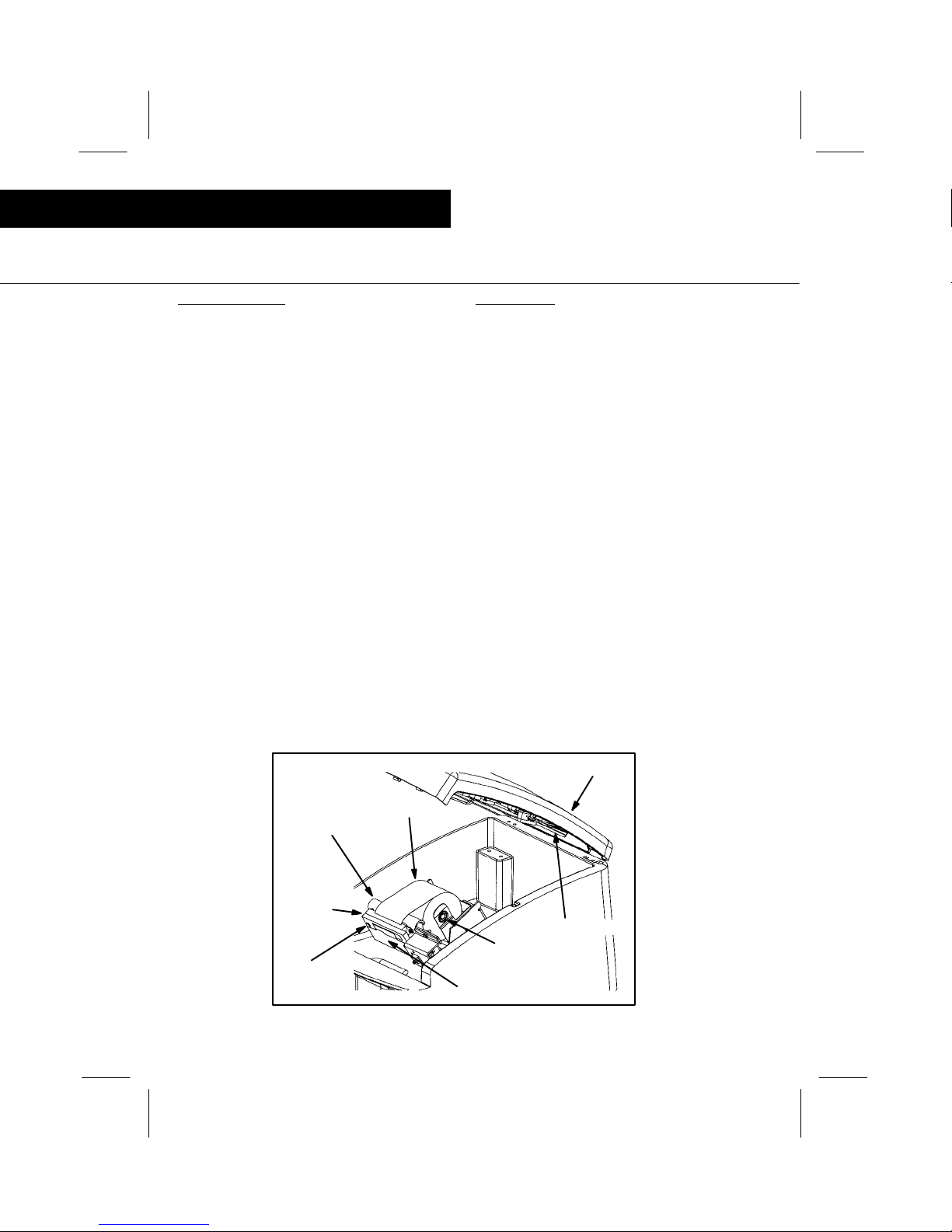
paper roll / printer ribbon
Installation
PAPER ROLL
Install (replace) the Paper Roll as follows:
Pull the Access Panel ( see FIGURE #7 ) for-
ward and lift the Keyboard. A self--contained
bracket / spring will retain it in position.
Tilt the Printer Mechanism forward, and remove
the old Paper Roll Core.
Remove the Printer Ribbon as discussed to the
left.
Install the new paper roll between the retainers
so that the paper feeds from the top of the roll
as shown in ( FIGURE #8 ).
Route the leading edge of the paper over the
top of the arched metal bracket and down into
the slot at the top of the Printer Mechanism.
Press the Paper Advance Key on the Keyboard
(see FIGURE #9 ) to advance the paper.
Replace the Printer Ribbon as discussed to the
left.
Return the Printer Mechanism to its upright
position.
Lower the the Keyboard, while feeding the lead-
ing edge of the paper through the Cutoff Slot.
FIGURE #8
PRINTER PAPER / RIBBON
(RETAINER BRACKET NOT SHOWN FOR CLARITY)
Paper Roll
Roll Retainer
Printer Driver
Keyboard
PRINTER RIBBON
Install (replace) the Paper Ribbon as follows:
Pull the Access Panel ( see FIGURE #7 ) for-
ward and lift the Keyboard. A self--contained
bracket / spring will retain it in position.
Observe the Printer Mechanism.
The bottom portion is the driver and the top por-
tion contains the printer ribbon.
Remove the top portion by carefully pulling
straight forward.
Install the new ribbon in reverse order, making
sure the audit trail ( printer ) tape is located
above the printer ribbon.
If necessary, turn the adjusting screw on the left
side of the printer ribbon until the ribbon is tight.
Return the Printer Mechanism to its upright
position.
Lower the the Keyboard, while feeding the lead-
ing edge of the paper through the Cutoff Slot.
Cutoff Slot
Printer
Ribbon
Adjusting
Screw
Arched
Metal
Bracket

9
overview
Operator control module
The Operator Control Module is the interface between the Operator and the Sorter. All Sorter functions
are controlled here. Each component and function key is identified in the figure below. A complete de-
scription of each Key, Icon and Display Screen is included on the following pages.
Supervisor
Keylock
Accept Key
Motor On/Off Key
Numeric
Keypad
Lower Icon
Direct Select
Keys (5)
Upper Icon
Select Key
Upper Icon
Choice Key
Display
Printer (Optional)
BATCH TOTAL
.00
BATCH GRANDSUB
:
SELECT
FIGURE #9
OPERATOR CONTROL MODULE
(KEYBOARD)
Paper Advance
Key
Lock
Position
Unlock
Position

10
function keys
Operator control module
UPPER ICON CHOICE
Selects counting mode (Batch / Sub / Grand),
Bag Count or Clock Icons.
UPPER ICON SELECT
Changes the Display Screen as determined by
the UPPER ICON CHOICE Key.
LOWER ICON DIRECT SELECT (HOME
SCREEN)
ID
Identify totals by route, product, etc.
MEDIA
Add checks, rolled coin, etc. to batch total
quantity.
CURRENCY
Add currency to batch total quantity.
BAGSTOP
Changes the Display to allow selection or
change of the bagstop quantities.
NO ICON
Reserved for future use.
MOTORON/OFF
Starts / Stops the Sorting Motor.
ACCEPT
Transfers totals to next memory level.
NUMERIC KEYPAD
Determine specific amounts to be entered
into the Control.
Table of contents


