manuals.online logo
Brands
  1. Home
  2. •
  3. Brands
  4. •
  5. Dell
  6. •
  7. Laptop
  8. •
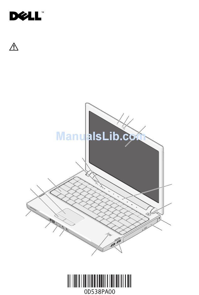
  9. Dell Latitude CS User manual

Dell Latitude CS User manual

ZZZGHOOFRP

'HOO/DWLWXGH&63RUWDEOH&RPSXWHUV
6(59,&(0$18$/
All manuals and user guides at all-guides.com
all-guides.com
All manuals and user guides at all-guides.com
ZZZGHOOFRP

'HOO/DWLWXGH&63RUWDEOH&RPSXWHUV
6(59,&(0$18$/
All manuals and user guides at all-guides.com
____________________
Information in this document is subject to change without notice.
© 1999 Dell Computer Corporation. All rights reserved.
Reproduction in any manner whatsoever without the written permission of Dell Computer Corporation is strictly forbidden.
Trademarks used in this text: Dell, the DELL logo, and Latitude are trademarks of Dell Computer Corporation.
Other trademarks and trade names may be used in this document to refer to either the entities claiming the marks and names or their products.
Dell Computer Corporation disclaims any proprietary interest in trademarks and trade names other than its own.
November 1999 P/N 0708R Rev. A01
All manuals and user guides at all-guides.com
i
&RQWHQWV
Recommended Tools. . . . . . . . . . . . . . . . . . . . . . . . . . . . . . . . . . . . . . . . . . . .2
Preparing to Work Inside Your Computer . . . . . . . . . . . . . . . . . . . . . . . . . . . .2
Screw Identification and Tightening . . . . . . . . . . . . . . . . . . . . . . . . . . . . . . . .3
ZIF Connectors . . . . . . . . . . . . . . . . . . . . . . . . . . . . . . . . . . . . . . . . . . . . . . . .5
Removing Field-Replaceable Parts and Assemblies . . . . . . . . . . . . . . . . . . . .6
Hard-Disk Drive Assembly. . . . . . . . . . . . . . . . . . . . . . . . . . . . . . . . . . . . .7
Memory Module Cover . . . . . . . . . . . . . . . . . . . . . . . . . . . . . . . . . . . . . . .7
Bottom Memory Module. . . . . . . . . . . . . . . . . . . . . . . . . . . . . . . . . . . . . .8
Top Memory Module. . . . . . . . . . . . . . . . . . . . . . . . . . . . . . . . . . . . . . . . .9
Display Assembly . . . . . . . . . . . . . . . . . . . . . . . . . . . . . . . . . . . . . . . . . .11
Display-Assembly Bezel. . . . . . . . . . . . . . . . . . . . . . . . . . . . . . . . . . . . . .13
Display-Assembly Latch. . . . . . . . . . . . . . . . . . . . . . . . . . . . . . . . . . . . . .15
LCD Panel . . . . . . . . . . . . . . . . . . . . . . . . . . . . . . . . . . . . . . . . . . . . . . .15
Replacing a Sharp LCD panel with a Sharp LCD panel or Replacing a
Samsung LCD panel with a Samsung LCD panel. . . . . . . . . . . . . . . . . .15
Replacing a Sharp LCD Panel with a Samsung LCD Panel or Replacing a
Samsung LCD Panel with a Sharp LCD Panel. . . . . . . . . . . . . . . . . . . . .16
Removing the Packing Bezel on a New Sharp LCD Panel. . . . . . . . .17
Packing a Defective Sharp LCD Panel for Return Shipping. . . . . . . .17
Keyboard Assembly. . . . . . . . . . . . . . . . . . . . . . . . . . . . . . . . . . . . . . . . .18
Palmrest Assembly . . . . . . . . . . . . . . . . . . . . . . . . . . . . . . . . . . . . . . . . .19
Bottom Assembly . . . . . . . . . . . . . . . . . . . . . . . . . . . . . . . . . . . . . . . . . .22
Reserve Battery . . . . . . . . . . . . . . . . . . . . . . . . . . . . . . . . . . . . . . . .22
Main Battery . . . . . . . . . . . . . . . . . . . . . . . . . . . . . . . . . . . . . . . . . . .23
Main Battery Release Latch. . . . . . . . . . . . . . . . . . . . . . . . . . . . . . . .23
Thermal Cooling Solution. . . . . . . . . . . . . . . . . . . . . . . . . . . . . . . . . .24
System Board Assembly . . . . . . . . . . . . . . . . . . . . . . . . . . . . . . . . . .26
Touch Pad . . . . . . . . . . . . . . . . . . . . . . . . . . . . . . . . . . . . . . . . . . . .29
Fan Assembly . . . . . . . . . . . . . . . . . . . . . . . . . . . . . . . . . . . . . . . . . .29
,QGH[
)LJXUHV Figure 1. Computer Orientation. . . . . . . . . . . . . . . . . . . . . . . . . . . . . . . . .1
Figure 2. Main Battery Assembly Removal. . . . . . . . . . . . . . . . . . . . . . . .3
All manuals and user guides at all-guides.com
ii
Figure 3. Screw Identification . . . . . . . . . . . . . . . . . . . . . . . . . . . . . . . . . .3
Figure 4. Disconnecting an Interface Cable. . . . . . . . . . . . . . . . . . . . . . . .5
Figure 5. Exploded ViewComputer . . . . . . . . . . . . . . . . . . . . . . . . . . . .6
Figure 6. Hard-Disk Drive Assembly Removal. . . . . . . . . . . . . . . . . . . . . .7
Figure 7. Bottom Memory Module Removal. . . . . . . . . . . . . . . . . . . . . . .8
Figure 8. Top Memory Module Removal . . . . . . . . . . . . . . . . . . . . . . . . .9
Figure 9. Status Indicator Panel Removal . . . . . . . . . . . . . . . . . . . . . . . .10
Figure 10. Display Assembly Removal . . . . . . . . . . . . . . . . . . . . . . . . . .11
Figure 11. Sharp Display-Assembly Bezel Removal . . . . . . . . . . . . . . . .13
Figure 12. Samsung Display-Assembly Bezel Removal. . . . . . . . . . . . . .14
Figure 13. Removing the Keyboard-Assembly Screws. . . . . . . . . . . . . .18
Figure 14. Removing the Palmrest-Assembly Screws . . . . . . . . . . . . . .19
Figure 15. Palmrest Assembly Removal . . . . . . . . . . . . . . . . . . . . . . . . .21
Figure 16. Bottom Assembly. . . . . . . . . . . . . . . . . . . . . . . . . . . . . . . . . .22
Figure 17. Main Battery Release Latch. . . . . . . . . . . . . . . . . . . . . . . . . .23
Figure 18. Thermal Cooling Solution Removal. . . . . . . . . . . . . . . . . . . . .24
Figure 19. System Board Assembly Removal. . . . . . . . . . . . . . . . . . . . .26
Figure 20. Microprocessor Removal . . . . . . . . . . . . . . . . . . . . . . . . . . . .29
7DEOHV Table 1. Screw Placement Mat with Component Screw Counts and Sizes. . 4
All manuals and user guides at all-guides.com
all-guides.com
iii
All manuals and user guides at all-guides.com
iv
5HDG7KLV)LUVW
A prerequisite for using this manual to service Dell computer systems is a basic
knowledge of PCs and prior training in PC troubleshooting techniques. In addition
to information provided in this manual, Dell provides the
Users Guide for trou-
bleshooting procedures and instructions on using the Dell Diagnostics to test
the computer system.
1RWHV1RWLFHVDQG&DXWLRQV
Throughout this guide, blocks of text may be accompanied by an icon and printed
in bold type or in italic type. These blocks are notes, notices, and cautions, and
they are used as follows:
NOTE: A NOTE indicates important information that helps you make better use
of your computer system.
127,&($127,&(LQGLFDWHVHLWKHUSRWHQWLDOGDPDJHWRKDUGZDUHRU
ORVVRIGDWDDQGWHOOV\RXKRZWRDYRLGWKHSUREOHP
&$87,21$&$87,21LQGLFDWHVDSRWHQWLDOO\KD]DUGRXVVLWXDWLRQ
ZKLFKLIQRWDYRLGHGPD\UHVXOWLQPLQRURUPRGHUDWHLQMXU\
All manuals and user guides at all-guides.com
Dell Latitude CS Portable Computers Service Manual 1
'HOO/DWLWXGH&63RUWDEOH
&RPSXWHUV6HUYLFH0DQXDO
This manual provides instructions for removing and replacing field-replaceable
components, assemblies, and subassemblies in your Dell Latitude portable
computer. Unless otherwise noted, each procedure in this manual assumes
the following conditions:
The computer and any attached peripherals are turned off, and the
peripherals are disconnected from theI/O panel on the back and right side
of the computer.
A part can be replaced by performing the removal procedure in reverse
order.
When the display assembly is open nearly 180 degrees, use a book or
something similar to support it. The angle of the display assembly with
respect to the bottom case should never exceed 180 degrees. Also, when
performing the procedures in this manual, the locations or directions relative to
the computer are as shown in Figure 1 unless otherwise specified.
)LJXUH&RPSXWHU2ULHQWDWLRQ
right side
left side
back of computer
front of computer
All manuals and user guides at all-guides.com
2 Dell Latitude CS Portable Computers Service Manual
5HFRPPHQGHG7RROV
Most of the procedures in thismanual require the use of one or more of the
following tools:
#0 and #1 magnetized Phillips-head screwdrivers
Small flat-blade screwdriver
5-mm socket wrench
7-mm socket wrench
Small plastic scribe
3UHSDULQJWR:RUN,QVLGH<RXU&RPSXWHU
Before you start to work on the computer, perform the following steps:
1. Save any work in progress and close all open application programs.
2. Turn off the computer and any attached peripherals.
NOTE: Make sure that the computer is turned off and not in suspend-to-
disk mode (S2D). If you cannot shut down the computer using its operating
system, press the power button for 4 seconds.
3. If the computer is docked in aC/Dock Expansion Station or C/Port
Advanced Port Replicator (APR), undock the computer.
4. Disconnect the computer and any attached peripherals from their electrical
outlets to reduce the potential for personal injury or shock. Also disconnect
any telephone or telecommunications lines from the computer.
5. Remove the power cable.
6. Disconnect all other external cables from the computer.
7. Remove any installed PC Cards.
127,&(0DNHVXUHWKDWWKHZRUNVXUIDFHLVFOHDQWRSUHYHQWVFUDWFK
LQJWKHFRPSXWHUFRYHU
127,&(7RDYRLGGDPDJLQJWKHV\VWHPERDUG\RXPXVWUHPRYHWKH
PDLQEDWWHU\EHIRUH\RXVHUYLFHWKHFRPSXWHU
8. Turn the computer over so the battery is on the lower right corner of the
computer, and remove the main battery assembly from the battery bay.
Slide the battery bay latch toward the right side of the computer to push
the back side of the battery up out of the battery bay (seeFigure 2).
All manuals and user guides at all-guides.com
Dell Latitude CS Portable Computers Service Manual 3
)LJXUH0DLQ%DWWHU\$VVHPEO\5HPRYDO
9. Ground yourself by touching the unpainted metal surface of the I/O panel
on the back of the computer.
While you work, periodically touch the I/O panel to dissipate any static
electricity that might harm components.
6FUHZ,GHQWLILFDWLRQDQG7LJKWHQLQJ
The illustrations in the following removal procedures provide lengths of the
correct screws for each procedure. Figure 3 shows examples. Match the actual
screw to the illustration to check for correct length.
)LJXUH6FUHZ,GHQWLILFDWLRQ
127,&(:KHQUHLQVWDOOLQJDVFUHZ\RXPXVWXVHDVFUHZRIWKHFRU
UHFWOHQJWK2WKHUZLVH\RXFRXOGGDPDJHWKHKDUGZDUH0DNHVXUH
WKDWWKHVFUHZLVSURSHUO\DOLJQHGZLWKLWVFRUUHVSRQGLQJKROHDQG
DYRLGRYHUWLJKWHQLQJ
battery battery latch
All manuals and user guides at all-guides.com
all-guides.com
4 Dell Latitude CS Portable Computers Service Manual
When you are removing and replacing components, photocopy the Table 1
placement mat as a tool to lay out and keep track of the component screws.
7DEOH6FUHZ3ODFHPHQW0DWZLWK&RPSRQHQW6FUHZ&RXQWV
DQG6L]HV
Hard-Disk Drive
Assembly:
M2 x 4 mm (2 each)
Memory Module
Cover:
M2.6 x 3 mm (2 each)
Display Assembly
Hinge to Bottom
Case Assembly:
M2.6 x 6 mm (4 each)
Display Assembly,
including Bezel:
M2 x 4 mm (6 each
[Sharp LCD] and 8 each
[Samsung LCD])
Rubber Screw
Covers (2 each [large]
and 4 each [small])
Keyboard
Assembly:
M2 x 16 mm (2 each)
Palmrest Assembly:
M2 x 2.5 mm (2 each
[palmrest top])
M2 x 4 mm (7 each
[computer bottom])
M2 x 2.5 mm (5 each
[battery bay])
Thermal Cooling
Solution:
M2 x 13 mm (4 each)
M2 x 4 mm (3 each)
System Board
Assembly:
M2 x 4 mm (8 each)
M2.6 x 6 mm (2 each)
PC Card Cover:
M2 x 4 mm (4 each)
(part of system
board screws)
Media Bay Port:
M2 x 2.5 mm (2 each)
Touch Pad:
M2 x 2.5 mm (2 each)
All manuals and user guides at all-guides.com
Dell Latitude CS Portable Computers Service Manual 5
=,)&RQQHFWRUV
Some of the computers interface connectors are zero insertion force (ZIF)
connectors. These connectors are not removable, but they must be released
to disconnect a cable from them (see Figure 4).
)LJXUH'LVFRQQHFWLQJDQ,QWHUIDFH&DEOH
127,&(7KH=,)FRQQHFWRUVDUHIUDJLOH7RDYRLGGDPDJHGRQRW
DSSO\WRRPXFKSUHVVXUHWRWKHPRYDEOHSDUWRIWKHFRQQHFWRU
To disconnect an interface cable from a ZIF connector, perform the following
steps:
1. Insert a small flat-blade screwdriver under the movable part of the
connector.
2. Pull gently upward on the movable part of the connector until it releases
the interface cable.
3. Grasp the interface cable and pull it out of the connector.
To reconnect an interface cable to a ZIF connector, perform the following
steps:
1. Use a small flat-blade screwdriver to open the movable part of the ZIF
connector.
2. Orient the end of the interface cable with the ZIF connector, and insert the
end of the cable into the connector.
3. While holding the cable in place, close the ZIF connector.
To ensure a firm connection, make sure the ZIF connector is completely
closed.
movable part of
connector
(do not remove)
All manuals and user guides at all-guides.com
6 Dell Latitude CS Portable Computers Service Manual
5HPRYLQJ)LHOG5HSODFHDEOH3DUWV
DQG $VVHPEOLHV
)LJXUH([SORGHG9LHZ³&RPSXWHU
The following subsections provide instructions for removing and replacing
field-replaceable parts and assemblies.
display
assembly
keyboard
palmrest
assembly
system board
hard-disk drive
main battery
bottom case assembly
status indicator panel
right hinge cover
left hinge cover
thermal cooling
solution
media-bay port cove
r
All manuals and user guides at all-guides.com
Dell Latitude CS Portable Computers Service Manual 7
+DUG'LVN'ULYH$VVHPEO\
)LJXUH+DUG'LVN'ULYH$VVHPEO\5HPRYDO
127,&(7RDYRLGGDPDJLQJWKHV\VWHPERDUG\RXPXVWUHPRYHWKH
PDLQEDWWHU\EHIRUH\RXVHUYLFHWKHFRPSXWHU
127,&(7KHKDUGGLVNGULYHLVYHU\VHQVLWLYHWRVKRFN+DQGOHWKH
DVVHPEO\E\LWVHGJHVGRQRWVTXHH]HWKHWRSRIWKHKDUGGLVNGULYH
FDVHDQGDYRLGGURSSLQJLW
127,&(0DNHVXUHWKDWWKHZRUNVXUIDFHLVFOHDQWRSUHYHQWVFUDWFK
LQJWKHFRPSXWHUFRYHU
1. Turn the computer over, and remove the two M2 x 4-mm screws from the
bottom of the hard-disk drive door (seeFigure 6).
The drive is located on the left side of the computer when the computer is
turned over.
2. Grasp the drive door, slide it up, and pull the drive out of the computer.
0HPRU\0RGXOH&RYHU
127,&(7RDYRLGGDPDJLQJWKHV\VWHPERDUG\RXPXVWUHPRYHWKH
PDLQEDWWHU\EHIRUH\RXVHUYLFHWKHFRPSXWHU
127,&(0DNHVXUHWKDWWKHZRUNVXUIDFHLVFOHDQWRSUHYHQWVFUDWFK
LQJWKHFRPSXWHUFRYHU
1. Close the display, and turn the computer upside down on a flat work
surface.
2. Remove the two M2.6 x 3-mm screws from the memory module cover,
and lift the cover up and out (two tabs are located on the opposite side of
the screw holes on the cover).
bottom of computer
hard-disk drive door
M2 x 4-mm screw(2)
All manuals and user guides at all-guides.com
8 Dell Latitude CS Portable Computers Service Manual
%RWWRP0HPRU\0RGXOH
)LJXUH%RWWRP0HPRU\0RGXOH5HPRYDO
To remove the bottom memory module, perform the following steps.
127,&(7RDYRLGGDPDJLQJWKHV\VWHPERDUG\RXPXVWUHPRYHWKH
PDLQEDWWHU\EHIRUH\RXVHUYLFHWKHFRPSXWHU
127,&(7KH0%PHPRU\PRGXOHGRHVQRWILWLQWKHERWWRP
PHPRU\PRGXOHVRFNHW
1. Remove the memory module cover.
2. Ground yourself by touching the unpainted metal surface of an I/O
connector on the computers back panel.
3. To release the memory module from its socket, carefully spread apart
the inner tabs of the memory module socket just far enough for the
memory module to disengage from the socket (it should pop up slightly)
(see Figure 7).
4. Lift the memory module out of its socket.
To replace a memory module, perform the following steps:
1. Align the memory modules edge connector with the slot in the center of
the memory module socket.
Memory modules are keyed, or designed to fit into their sockets in only
one direction. The slots on the system board are notched so that the
memory module can be firmly seated only one way.
2. With the module at a 45-degree angle, press the memory modules edge
connector firmly into the memory module socket.
3. Pivot the memory module down until it clicks into place.
4. If you do not hear a click as each end of the memory module snaps into the
tabs, remove the memory module and reinstall it.
memory
module
socket
inner tabs (2)
memory module
All manuals and user guides at all-guides.com
all-guides.com
Dell Latitude CS Portable Computers Service Manual 9
7RS0HPRU\0RGXOH
)LJXUH7RS0HPRU\0RGXOH5HPRYDO
127,&(7RDYRLGGDPDJLQJWKHV\VWHPERDUG\RXPXVWUHPRYHWKH
PDLQEDWWHU\EHIRUH\RXVHUYLFHWKHFRPSXWHU
1. Remove the status indicator panel.
Use a flat-blade screwdriver to press in on the three tabs that secure the
status indicator panel to the back panel of the computer (see Figure 9).
2. Remove the keyboard (seeFigure 13).
3. Remove the thermal cooling solution (seeFigure 18).
4. Ground yourself by touching the unpainted metal surface of an I/O
connector on the computers back panel.
5. To release the memory module from its socket, carefully spread apart
the inner tabs of the memory module socket just far enough for the
memory module to disengage from the socket (it should pop up slightly)
(see Figure 8).
inner tabs (2
)
memory modul
e
All manuals and user guides at all-guides.com
10 Dell Latitude CS Portable Computers Service Manual
6. Lift the memory module out of its socket.
)LJXUH6WDWXV,QGLFDWRU3DQHO5HPRYDO
To replace a memory module, perform the following steps.
127,&(7KH0%PHPRU\PRGXOHILWVWKHWRSPHPRU\PRGXOH
VRFNHWRQO\
1. Align the memory modules edge connector with the slot in the center of
the memory module socket.
Memory modules are keyed, or designed to fit into their sockets in only
one direction. The slots on the system board are notched so that the
memory module can be firmly seated only one way.
2. With the module at a 45-degree angle, press the memory modules edge
connector firmly into the memory module socket.
3. Pivot the memory module down until it clicks into place.
4. If you do not hear a click as each end of the memory module snaps into the
tabs, remove the memory module and reinstall it.
tabs (3)
All manuals and user guides at all-guides.com
Dell Latitude CS Portable Computers Service Manual 11
'LVSOD\$VVHPEO\
)LJXUH'LVSOD\$VVHPEO\5HPRYDO
127,&(7RDYRLGGDPDJLQJWKHV\VWHPERDUG\RXPXVWUHPRYHWKH
EDWWHU\EHIRUH\RXVHUYLFHWKHFRPSXWHU
1. Remove the status indicator panel.
2. Remove the right plastic hinge cover by sliding it to the right of the display
assembly.
3. Remove the two M2.6 x 6-mm hinge screws that secure the right hinge to
the bottom case (see Figure 10).
4. Remove the left plastic hinge cover by sliding it to the left of the display
assembly.
status indicator
panel
display assembly
M2.6 x 6-mm
screws (4)
left hinge cover
right hinge cove
display-assembly
interface wire
display-assembly
inverter wire
All manuals and user guides at all-guides.com
12 Dell Latitude CS Portable Computers Service Manual
5. Remove the two M2.6 x 6-mm hinge screws that secure the left hinge to
the bottom case.
6. Carefully disconnect the display-assembly interface wire connector,
located on the left side of the display assembly, from the system board.
The female connector attached to the display-assembly interface wire is
keyed to fit into the male connector one way only.
On some models, the interface wire is routed under the left hinge. To
remove the wire from under the hinge, remove all three M2 X 4-mm
screws attaching the left hinge to the display-assembly top cover (see Fig-
ure 11). For models that do not route the interface wire under the left
hinge, the wire is removed without removing the left hinge.
7. Carefully disconnect the display-assembly inverter wire connector, located
on the right side of the display assembly, from the system board.
The female connector attached to the display-assembly inverter wire is
keyed to fit into the male connector one way only.
8. Lift the display assembly from the bottom assembly.
All manuals and user guides at all-guides.com

Other manuals for Latitude CS

2

Other Dell Laptop manuals

Dell Alienware M15x - GAMING NOTEBOOK - COSMIC User manual

Dell

Dell Alienware M15x - GAMING NOTEBOOK - COSMIC User manual

Dell Inspiron 14 5000 Series User manual

Dell

Dell Inspiron 14 5000 Series User manual

Dell Latitude ATG D620 User manual

Dell

Dell Latitude ATG D620 User manual

Dell Vostro 3590 User manual

Dell

Dell Vostro 3590 User manual

Dell E5400 - Latitude - Core 2 Duo 2.4 GHz User manual

Dell

Dell E5400 - Latitude - Core 2 Duo 2.4 GHz User manual

Dell Latitude XT3 User manual

Dell

Dell Latitude XT3 User manual

Dell Alienware x16 R1 Operation and maintenance manual

Dell

Dell Alienware x16 R1 Operation and maintenance manual

Dell Latitude E5250 User manual

Dell

Dell Latitude E5250 User manual

Dell Inspiron 3500 User manual

Dell

Dell Inspiron 3500 User manual

Dell Inspiron 2000 Guide

Dell

Dell Inspiron 2000 Guide

Dell Chromebook 3400 User guide

Dell

Dell Chromebook 3400 User guide

Dell SmartStep 100N User manual

Dell

Dell SmartStep 100N User manual

Dell Vostro 14 5410 Operation and maintenance manual

Dell

Dell Vostro 14 5410 Operation and maintenance manual

Dell Inspiron 22 3000 SERIES User manual

Dell

Dell Inspiron 22 3000 SERIES User manual

Dell Inspiron 1420 User manual

Dell

Dell Inspiron 1420 User manual

Dell Vostro 3000 User guide

Dell

Dell Vostro 3000 User guide

Dell Precision 7550 User guide

Dell

Dell Precision 7550 User guide

Dell Inspiron 14 3000 Series Operation and maintenance manual

Dell

Dell Inspiron 14 3000 Series Operation and maintenance manual

Dell Inspiron 8000 User manual

Dell

Dell Inspiron 8000 User manual

Dell Vostro 3300 User guide

Dell

Dell Vostro 3300 User guide

Dell XPS 15 User manual

Dell

Dell XPS 15 User manual

Dell XPS 13 Operation and maintenance manual

Dell

Dell XPS 13 Operation and maintenance manual

Dell I15RN-3647BK User manual

Dell

Dell I15RN-3647BK User manual

Dell Vostro 2521 User manual

Dell

Dell Vostro 2521 User manual

Popular Laptop manuals by other brands

Lenovo Legion n 5 Pro 16IAH7H user guide

Lenovo

Lenovo Legion n 5 Pro 16IAH7H user guide

HP Pavilion XF315 Information note

HP

HP Pavilion XF315 Information note

Lenovo ThinkPad Edge E420s Guia do usuário

Lenovo

Lenovo ThinkPad Edge E420s Guia do usuário

Fujitsu Siemens Computers Siemens AMILO L Series Easy guide

Fujitsu Siemens Computers

Fujitsu Siemens Computers Siemens AMILO L Series Easy guide

Lenovo IdeaPad Z485 Notice

Lenovo

Lenovo IdeaPad Z485 Notice

HP Pavilion g7-2100 user guide

HP

HP Pavilion g7-2100 user guide

Asus E8923 E-manual

Asus

Asus E8923 E-manual

Asus K50AB Hardware user manual

Asus

Asus K50AB Hardware user manual

Sony VGN-SR250J/B Specifications

Sony

Sony VGN-SR250J/B Specifications

Acer TravelMate 3250 Service guide

Acer

Acer TravelMate 3250 Service guide

Toshiba Satellite L745D-S4230 Specifications

Toshiba

Toshiba Satellite L745D-S4230 Specifications

Panasonic Toughbook CF-19CHBAXBM Service manual

Panasonic

Panasonic Toughbook CF-19CHBAXBM Service manual

IBM ThinkPad T20 owner's manual

IBM

IBM ThinkPad T20 owner's manual

Toshiba M505 S4947 - Satellite - Core 2 Duo GHz Specifications

Toshiba

Toshiba M505 S4947 - Satellite - Core 2 Duo GHz Specifications

Panasonic Toughbook CF-F9KWHZG1M Specifications

Panasonic

Panasonic Toughbook CF-F9KWHZG1M Specifications

Packard Bell EasyNote LG user manual

Packard Bell

Packard Bell EasyNote LG user manual

PRIXTON PC15PRO manual

PRIXTON

PRIXTON PC15PRO manual

Lenovo Yoga Slim 7i ProX Hardware Maintenance Manual

Lenovo

Lenovo Yoga Slim 7i ProX Hardware Maintenance Manual

manuals.online logo
manuals.online logoBrands
  • About & Mission
  • Contact us
  • Privacy Policy
  • Terms and Conditions

Copyright 2025 Manuals.Online. All Rights Reserved.