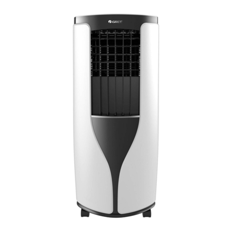
DELLA 048-TL-PAC12K User manual

1
NOTICE:
If your package is missing parts or you are having issues with assembly, please call Belleze Furniture directly at
(909)-595-5901. The Belleze Furniture customer service team will address any questions or concerns you may have.
Have this manual open and ready for reference.
CUSTOMER SERVICE:
909-595-5901
9:00AM - 6:00PM PST (Monday - Friday)
Model# 048-TL-PAC10K / 12K / 14K
USER’S MANUAL
PORTABLE AIR CONDITIONER
⚠CAUTION! WARNING: Do not use this device before reading these instructions.
www.dellaproductsusa.com

2
Table of Contents
Warnings & Precautions ---------------------------------------------------------------------
Technical Specication ------------------------------------------------------------------------
Parts and Features ------------------------------------------------------------------------------
Installation guide ------------------------------------------------------------------------------
Control Panel ------------------------------------------------------------------------------------
Remote Control ------------------------------------------------------------------------------------
Care and Maintenance ---------------------------------------------------------------------------
Troubleshooting -------------------------------------------------------------------------------
Error Code Chart -------------------------------------------------------------------------------
03
04
05
07
12
14
17
19
20

3
When using electrical appliances, basic safety precautions should always be followed including the following:
READ ALL INSTRUCTIONS BEFORE USE
1. To disconnect, turn o the unit and then unplug the power
cord.
2. Close supervision is necessary if the appliance is used by or
near children.
3. Do not attempt to repair or replace any part of this appliance
unless it is specically recommended in this manual. Contact
dealer, seller, a qualied electrician, or an authorized service
center to repair the product.
4. Do not immerse cord, plug, or the appliance in water or
other liquid.
5. Do not operate any appliance with a damaged cord or plug
or after the appliance malfunctions, or has been dropped
or damaged in any manner. See warranty to return for
examination, repair, or electrical or mechanical adjustment.
Appliance serviced only by authorized agent.
6. The use of accessory attachments (not recommended or sold
by the manufacturer) may cause re, electric shock or injury.
7. Do not use outdoors.
9. Do not use appliance for anything other than intended use.
10. Always place this unit on a solid and level surface.
11. Do not cover the air inlet or vents.
12. Do not use extension cord. This appliance is for household
use only.
13. This unit must be connected to a grounded power supply.
14. Do not place the appliance near any heat source.
15. Do not use this appliance near ammable gases or liquids
or other combustibles.
16. Make sure the power cord is plugged rmly and completely
into the outlet.
17. Be sure to remove all packaging material before using the
appliance.
18. Immediately unplug the product if the appliance is making
unusual sounds or is emitting smoke or odor.
19.Always turn o and unplug the appliance if not used for
extended period of time.
SAVE THESE INSTRUCTIONS

4
Specications
Model Number 048-TL-PAC10K 048-TL-PAC12K 048-TL-PAC14K
Dimensions (W x D x H) 17.32”x12.79”x27.36” 17.52”x14.76”x28.35” 17.52”x14.76”x28.35”
Net Weight 55.11 lb 59.52 lb 68.34 lb
Gross Weight 70.55 lb 74.96 lb 85.98 lb
Power Rating 1120 W 1250 W 1430 W
Voltage 115 V 115 V 115 V
Frequency 60 Hz 60 Hz 60 Hz
Capacity 10000 Btu/h 12000 Btu/h 14000 Btu/h

5
Parts & Features
AB
CE
F
I
H
J
G
D
A. Air Outlet Grill
B. Control Panel
C. Carrying Handle
D. Casters / Wheels
E. Air Filter
F. Power Cord
G. Continuous Drainage Outlet
H. Air Exhaust
I. Manual Drainage Outlet
J. Air Intake Grill
¹ Only for 048-TL-PAC10K

6
Parts & Features
K. Window Kit Adapter
L. Window Kit Adapter Extension
M. Remote Control
N. Screws
O. Drain Hose
P. Exhaust Hose
Q. Window Sliding Kit
R. Rubber Plug
S. Exhaust Host Connector
T. Foam Seal Type 1
U. Foam Seal Type 2
K
P
L
Q
M
R
N
S U
O
T

7
Installation Guide
Placing the Unit
Place the unit on smooth level surface.
Allow at least 12” of clearance around the unit.
Plug the unit to a grounded power socket.
Place the unit near window for exhaust installation.
NOTE:
This unit is intended for indoor use only.
This unit works best in enclosed area.
⚠CAUTION! WARNING: Keep the unit away from direct sunlight.
Exhaust Installation
1. Extend either end of the exhaust hose and screw the hose to the exhaust connector.
2. Screw the other end to the window kit adapter and the adapter extension.
3. Slide and lock the exhaust hose connector end into the air exhaust on the unit.
4. Ax the window kit adapter into the window sliding kit.
NOTE:
Make sure there is no sharp bends or sags on the exhaust hose

8
Installation Guide
Window Sliding Kit Installation
Your window sliding kit is designed to t most standard window.
Cut the window sliding kit if the window width is shorter than the minimum length of the sliding kit.
NOTE:
Cutting the window kit will reduce the maximum length it can extend.
Slide the window slider kit panels together and screw to lock the panels in place.
Install the sliding kit on the window
1. Slide open the window sash and place the window sliding kit on the window stool / against the window
jamb. Adjust the length of the sliding kit accordingly. Lock the sliding kit by screwing down the two
screw on it.
2. Close the window sash against the window sliding kit.
Top Hung Window Sliding Sash Window

9
Installation Guide
Foam Seal Installation (Optional)
1. Cut the foam seal type 1 (adhesive type) to the proper length and attach them to the window and the
window stool / window jamb.
2. Attach the window sliding kit to the window.
3. Close the window against the window sliding kit.
4. Cut the foam seal type 2 to an appropriate length and seal the open gap.

10
Installation Guide
Drain Hose Installation
Water need to be drain for“DRY”mode operation.
To install drain hose,
1. Unscrew the drain cap from the drain outlet.
2. Connect one end of the drain hose to the drain outlet, then lead
the other end into a drain that is lower than the drain outlet.
NOTE:
Make sure the drain height and the drain hose is not higher than
that of the drain outlet.

11
Installation Guide
Grounding
This product must be grounded. If it should malfunction or breakdown, grounding provides a path of least
resistance for electric current to reduce the risk of electric shock.
For additional safety, the power cord features an integrated circuit breaker. Test and reset the buttons are
provided on the plug case.
The circuit breaker should be tested periodically by pressing the TEST button. If it does not cause the circuit
breaker to trip, or if the RESET button will not stay engaged, unplug the unit immediately and contact your
service technician.
⚠CAUTION! WARNING: Improper connection of the equipment grounding conductor can result in a risk
of electric shock. Check with a qualied electrician or serviceman if you are in doubt as to whether the prod-
uct is properly grounded.
⚠CAUTION! WARNING: DO NOT modify the plug provided with the product if it does not t the outlet.
Have a proper outlet installed by a qualied electrician.

12
User Instruction
Power ON / OFF
Plug the unit into a grounded socket. The screen will display“- -” and turn into stand by mode.
Press the POWER button once to turn the unit on.
Press the POWER button once more to turn the unit o.
⚠CAUTION! WARNING: DO NOT unplug the unit when it is still“ON”
Cool Mode
Press MODE button when the machine is turned on until the cool mode indicator is lit.
Press the FAN button to choose the fan speed. The fan speed indicator will lit.
You can choose between “high”,“medium”,“low”, or“auto” fan speed.
Press the and button to set to desired temperature.
Dry Mode
Press the MODE button until the dry mode indicator is lit.
The screen will display code“dH”.
At the same time, the “auto”fan speed indicator will also lit.
NOTE: Fan speed cannot be adjusted in this mode.
Fan Mode
Press the MODE button until the Fan mode indicator is lit. In this mode, you can select fan speed to“high”,
“med”,or“low”.
The screen will also displays“Ξ Ξ” for high speed, “= =”for medium speed, and“− −”for low speed.
NOTE: AUTO cannot be selected in this mode.

13
User Instruction
Start Up Timer
Press the TIMER button when the unit is in stand by mode (plugged into power but have not power on).
The time indicator and the number of hours on the screen will ash. Tap or hold or to change
the delay start timer in 0.5 hour increments up to 10 hours, and then 1 hour increments up to 24 hours.
After 5 seconds, the timer indicator and the display will stop ashing. The unit will count down the time until
startup.
To cancel setting, press the timer button again, and the timer indicator will turn o.
NOTE: The unit will start working using the mode previously set.
Shut Down Timer
Press the TIMER button when the unit is powered on.
The time indicator and the number of hours on the screen will ash. Tap or hold or to change
the delay start timer in 0.5 hour increments up to 10 hours, and then 1 hour increments up to 24 hours.
After 5 seconds, the timer indicator and the display will stop ashing. The unit will count down the time until
shut down.
To cancel setting, press the timer button again, and the timer indicator will turn o.

14
User Instruction
Insert or Replace Batteries on Remote Control
Remove the cover on the back of the remote control; Replace the old batteries with two new AAA 1.5V bat-
teries.
Replace the cover.
NOTE: Remove the batteries if the remote control is not use for an extended period of time.
⚠CAUTION! WARNING: DO NOT mix old and new batteries.
⚠CAUTION! WARNING: DO NOT mix alkaline batteries, carbon-zinc batteries, or rechargeable batteries.
Using the Remote Control
Point the remote control at the control panel on the unit. The remote control must be less than 16.4ft (5m)
away from the unit (without obstacles between the remote control and the unit).
The buttons on the remote control mimics the same control function as that on the control panel.

15
User Instruction
Power ON / OFF
Plug the unit into a grounded socket. The screen will display“− −” and turn into stand by mode.
Press the POWER button on the remote control once to turn the unit on.
Press the POWER button once more on the remote control to turn the unit o.
⚠CAUTION! WARNING: DO NOT unplug the unit when it is still“ON”
Cool Mode
Press MODE button when the machine is turned on until the arrow pointed to .
Press the FAN speed button to choose the fan speed. The arrow will point at fan speed indicator on the
right.
You can choose between “high”, “med”, “low”, or “auto” fan speed.
Press the ▲and ▼button to set to desired temperature
Dry Mode
Press the MODE button until the arrow pointed to .
At the same time, the fan speed indicator arrow will pointed to “low”.
NOTE: Fan speed cannot be adjusted in this mode.
Fan Mode
Press the MODE button until the arrow pointed to . In this mode, you can select fan speed to“high”,
“med”, or“low”by pressing the FAN SPEED button.
NOTE: You cannot select auto fan speed in this mode.
Auto Mode
Press the MODE button until the arrow pointed to .
Press the FAN SPEED button to choose between “high”,“medium”, “low”, and “auto” fan speed.
NOTE: The unit will automatically run in fan mode if the room temperature is below 73°F (23°C) and cool
mode if the room temperature is above 73°F (23°C).
Sleep Mode
When the unit is in Cool, Auto, or Dry mode, you can press the SLEEP button on the remote control to
make the unit run in sleep mode. In this mode, the fan speed will be set to“low”automatically.
In Cool mode, the selected temperature will increase by 1°F every 60 minutes for 2 hours after sleeping
mode is selected. The new temperature will be maintained for 6 hours, and the unit will switch into stand by
mode after.
In Auto and Dry mode, the temperature will be set automatically and fan speed will be kept in“low”
NOTE: you cannot use Sleep mode when using Fan mode.

16
User Instruction
Start up Timer
Press the TIMER button when the unit is in stand by mode (pugged into power but have not powered
on) and the arrow is pointed at “ON “.
Press the ▲and ▼button to make the desire setting. Conrm the setting by pressing the TIMER
button again. The time will display on the screen and the“h”symbol will ash.
To cancel the setting, press the TIMER button again and the time indicator will turn o.
Shut down Timer
Press the TIMER button when the unit powered on and the arrow is pointed at “ OFF“.
Press the ▲and ▼button to make the desire setting. Conrm the setting by pressing the TIMER
button again. The time countdown will display on the screen.
To cancel the setting, press the TIMER button again and the time indicator will turn o.
Swing Function
Press the SWING button to enable the air deector swing function. Press the SWING button again to disable
the swing function.
°C/°F function
Press the °C/°F button to switch between degree Celsius and degree Fahrenheit.

17
Clearing the unit housing:
Clean the surface with a damp cloth and dry it with a soft towel.
⚠CAUTION! WARNING: DO NOT use harsh cleaners, was, or polish on the unit. Be sure to dry the unit,
excess water may cause damage to the unit.
⚠CAUTION! WARNING: Unplug the power cord before cleaning.
User Instruction
Care and Maintenance
Draining the unit:
Condensate will residue inside the unit when operate. Condensate need to be drained to keep the unit
working.
Continue Drainage
Drain hose can be installed on the unit to continue drainage.
See drain hose installation for installation instruction.
Manual Drainage
1. Unplug the unit and move the unit to a suitable drain location.
2. Uncap the drain cap from the bottom drain outlet to drain.
NOTE: Error code“Ft”will appears on the display if the water tank is full.

18
User Instruction
Storage:
If the unit will not be used for an extended period of time:
1. Drain the water tank completely. Leave the drain outlet unplug for longer time and allow all water to
drain . Once the tank is completely drained and no more water ows out, reinstall the rubber plug and
cap.
2. Remove and clean the lter, allow it to dry completely, then reinstall it.
3. Remove the batteries from the remote control.
4. Store the air conditioner in a cool, dry place.
Avoid expose to direct sunlight, extreme temperature, and/or excessive dust.
Before using the unit again:
1. Make sure the lter and drain cap are in place.
2. Make sure the power cord is in good condition and without any cracks or damage.
3. Place new batteries in remote control.
4. Install the unit as described in the installation instruction.
Clearing the lter:
To keep your air conditioner working eciently, you should clean the
lters every week of operation.
Grasp the upper panel tab and take o the lter behind the grill on the
back panel as shown in the gure to the right.
Wash the lter using liquid dish-washing detergent and warm water.
Rinse lter thoroughly. Gently shake excess water from the lter. Be
sure lter is thoroughly dry before replacing. You may also vacuum the
lter.
Replace the lter after the lter is dry.

19
Trouble shooting
Problem Possible Reasons Solutions
Unit does not work
No Power Make sure the unit is plugged into
a grounded power socket
Electrical Protection Check the house fuse / circuit
breaker box.
Water tank is full Drain the tank and reset setting.
Power Failure
A 3 mins protective time delay
may prevent the unit to operate
after a power failure.
Unit does not cool properly
Not enough time for the unit to
cool the area
Allow the unit to operate for a
sucient time to cool the room
Airow is restricted Make sure nothing is blocking the
air inlet / exhaust vent
Dirty lter Clean the lter
The setting is too high Lower the desired temperature
using the control panel
Hot air getting into the room The unit works best in an enclose
area
Room temperature is too high Allow the unit to operate for a
sucient time to cool the room
Unit runs too much
The room is too large Make sure the capacity of your
unit is adequate for the room size
Doors or windows are open Make sure to close all openings

20
Error Code Chart
Error Code Description Solution
Lt Low Temperature Wait until the unit nish defrosting
PF Probe Failure Damaged Sensor, contact customer service
Ft Full water tank Empty the water tank
This manual suits for next models
2
Table of contents
Other DELLA Air Conditioner manuals

DELLA
DELLA 048-GM-48383 User manual

DELLA
DELLA 048-GM-48335 User manual

DELLA
DELLA 048-TL-9K1V-19S User manual

DELLA
DELLA 048-MS-T1159K User manual

DELLA
DELLA 048-TL-PAC08K User manual

DELLA
DELLA 048-GM-48265 User manual

DELLA
DELLA 048-MS-12 User manual

DELLA
DELLA 048-MS-12 User manual

DELLA
DELLA 048-GM-48382 User manual

DELLA
DELLA 048-GM-48265 User manual


