Delphin ProfiMessage User manual


ProfiMessage
Copyright©2003-2015DelphinTechnologyAG.Allrightsreserved.
Thisdocument'scontent,especiallytext,images,andgraphicsareprotectedby
copyright.Whennototherwisestated,thecopyrightbelongstoDelphinTech-
nologyAG,Lustheide81,in51427BergischGladbach,Germany.
Allthetrademarksandbrandsusedinthismanualreferonlytotherespective
productortrademarkholder.DelphinTechnologyclaimsnorightsotherthan
thosetoitsowntrademarksandbrands.
2
Delphin Technology AG
Dezember 2015
ProfiMessage Manual

ProfiMessage
Contents
1 Introduction 9
1.1Safetyadvice 10
1.2Systemrequirements 11
1.3Symbolsused 11
2 Getting started 13
2.1Installingprograms 13
2.2PCconnection 14
2.3Startingthedevice 19
2.4StartingtheProfiMessagedevice 19
2.5Basicsettings 20
3 ProfiMessage displays and connections 22
3.1Powersupply 23
3.2LEDdisplays,LAN,USB 24
3.3GeneralLEDdisplays 24
3.4COMinterfaces,CAN 26
3.5I/Omoduleconnections(terminalblocks) 29
3.5.1AAST 29
3.5.2ADFT 30
3.5.3ADGT 30
3.5.4ADIT 31
3.5.5ADVT 32
3.5.6AMDT 32
3.5.7DIOT 33
3.5.8IOIT 33
3.5.9OTPT 34
3.6I/Omoduleinstallationandremoval 34
3.7Installinginternalmemorycard 39
3.8Installinginternalbattery 44
4 Configuration and operation 50
4.1Overview 50
4.2ProfiMessagedeviceconfiguration 52
4.3Connectingslavedevices 52
4.4Settingsforalldialogues 55
4.4.1Additionalsettingstab 57
4.4.2Sensorcompensationtab 58
4.4.3Informationtab 61
4.4.4Basicchannelselection 61
4.4.5Advancedchannelselection 62
3
Delphin Technology AG
Dezember 2015
ProfiMessage Manual

ProfiMessage
4.4.6Triggeroptionsedgeandlevel 63
4.4.7Inheritstatus 64
4.5Systemchannels 64
4.5.1Systemmonitoring 65
4.5.2LED 66
4.5.3Directory(Usermanagement) 68
4.5.4Clock 70
4.5.5Systemsettings 73
4.5.6Networksettings 75
4.6ConfiguringI/Omodulechannels 77
4.6.1I/Omodule 77
4.6.2AMDTI/Omodule 80
4.6.3Analogueinput 80
4.6.3.1Voltagesensortype 81
4.6.3.2Resistancesensortype 82
4.6.3.3Sensortypecurrent 83
4.6.3.4Sensortypecurrent0/4mAto20mA 84
4.6.3.5Resistancethermometersensortype 85
4.6.3.6Thermocouplesensortype 87
4.6.3.7Phprobesensortype 88
4.6.3.8Advancedsettingstab 89
4.6.3.9Measuringtimetab 90
4.6.4Digitalinputwithcounter/frequencymeasurement 90
4.6.5Digitalinput 93
4.6.6Analogueoutput 93
4.6.7Digitaloutput 95
4.7Configuringsoftwarechannels 96
4.7.1Adder 96
4.7.2Operatinghourscounter 97
4.7.3Differentiator 97
4.7.4Event 97
4.7.5Flip-flop 97
4.7.6Limitvalue 100
4.7.7Pulsegenerator 101
4.7.8Integrator 112
4.7.9Channelgroup 113
4.7.10Linearisation 113
4.7.11Logic 114
4.7.12Markers 118
4
Delphin Technology AG
Dezember 2015
ProfiMessage Manual

ProfiMessage
4.7.13Average 119
4.7.14PIDcontroller 120
4.7.14.1Introductiontocontroltechnology 120
4.7.14.2Controllerparametersettings 124
4.7.14.3ConfiguringPIDcontrollers 126
4.7.15Pulsewidthmodulation(PWM) 132
4.7.16Calculationchannel 132
4.7.17Batchalarms 137
4.7.18Shiftregister 137
4.7.19Setpoint 138
4.7.20Statistics 142
4.7.21Statusfilter 143
4.7.22Statusgenerator 144
4.7.23Statusmonitoring 145
4.7.24Stopwatch 146
4.7.25Systemmonitoring 148
4.7.26Tolerancefilter 150
4.7.27Trigger 151
4.7.28Clock 152
4.7.29Alarmclock 153
4.7.30Counter 155
4.7.31Timedelay 158
4.8Configuringinterfaces 161
4.8.1TCP/IPservices 162
4.8.1.1ModbusDevice(Server) 162
4.8.1.2ModbusDevice(Client) 164
4.8.1.3Modbuschannel 165
4.8.2CANconnection 168
4.8.2.1CANprotocol 170
4.8.2.2CANbuschannel 171
4.8.3COMconnection 175
4.8.3.1PROFIBUSprotocol 178
4.8.3.2PROFIBUSchannel 179
4.8.3.3ModbusRTUSlave/Master 182
4.8.3.4User-definedprotocol 189
4.8.4LAN 203
5.1Devicememory 206
6 Connection examples 207
6.1Connectingsensors 207
5
Delphin Technology AG
Dezember 2015
ProfiMessage Manual

ProfiMessage
6.2Connectingactuators 210
7 Measurement technology notes 212
7.1Galvanicisolation 212
7.2Earthing 213
7.3Earthloops 214
7.4Shielding 215
7.5ESDprotection 216
7.6Potentialdifferences 217
8 Technical specifications 220
8.1Maindevice 220
8.2I/Omodules:AAST,ADGT,ADITandADVT 223
8.3I/Omodules:DIOT,IOITandOTPT 225
8.4ADFTI/Omodule 226
8.5AMDTI/Omodule 229
9 AMDT I/O module 230
9.1Hardware 230
9.1.1Projectplanninganddesign 230
9.1.2Connectorpanel(industrial) 232
9.1.3Connectorpanel(laboratory) 233
9.1.4Blockdiagrams 233
9.1.5Technicalspecifications 235
9.1.5.1Galvanicisolation 235
9.1.5.2Analogueinputs 236
9.1.5.3Analogueoutputs 237
9.1.5.4Digitalinputs 238
9.1.5.5Counter 238
9.1.5.6Digitaloutputs 239
9.1.6Appendix 239
9.1.6.1ACcouplingforanalogueinputs 239
9.1.6.2Externalswitching 240
9.2Function 242
9.2.1Operatingmode 242
9.2.1.1Batchrecording 242
9.2.1.2Continuousrecording 243
9.2.1.3Signalsimulation 245
9.2.1.4SynchronisingtwoAMDTmodules 249
9.2.2Triggeringandrecording 253
9.2.2.1Redundanttriggersource 255
9.2.3Timesignal 257
6
Delphin Technology AG
Dezember 2015
ProfiMessage Manual

ProfiMessage
9.2.3.1Digitalfilter 257
9.2.3.2Digitalintegrator 257
9.2.4FFTanalysis/frequencyspectrum 258
9.2.5Characteristicvalues 259
9.2.5.1"Maximumvalue","minimumvalue"characteristicvalues 261
9.2.5.2Peak-to-peakcharacteristicvalue 262
9.2.5.3"Artihm.Average" 263
9.2.5.4"TrueRootmeansquare(TRMS)"characteristicvalue 263
9.2.5.5"Frequencyofmainvibration"characteristicvalue 264
9.2.5.6"Amplitudeofthemainvibration"characteristicvalue 264
9.2.5.7"Phaseofmainvibration"characteristicvalue 265
9.2.5.8"Amplitudeofthe1X/2X/3X/xXvibration"characteristicvalue 265
9.2.5.9"Phaseofthe1X/2X/3X/xXvibration"characteristicvalue 267
9.2.5.10“Rotationspeed” 268
9.2.5.11"Maximumvect.sum"characteristicvalue 269
9.2.5.12"Artihm.averageofproduct” 269
9.2.5.13"Frequencyofmaximumline,band1/2/3"characteristicvalue 270
9.2.5.14"Amplitudeofmaximumline,band1/2/3"characteristicvalue 270
9.2.5.15"RMSvalue,band1/2/3"characteristicvalue 273
9.2.5.16"Total"characteristicvalue 274
9.2.5.17“Residualvalue” 275
9.2.6Frequencyandrotationspeedmeasurement 276
9.2.7Measuringofphaseangle 278
9.2.8Monitoring 280
9.3Configurationandoperation 281
9.3.1ConfigurationwithDataServiceConfigurator 281
9.3.1.1Configuration/settingsforI/Omodule 283
9.3.1.2I/Omodulestatus/measurementblockcounter 291
9.3.1.3Configuring/settingsforananalogueinput 291
9.3.1.4Configuration/settingsforFFT/spectrum 296
9.3.1.5Configuration/settingsforcharacteristicvalue 297
9.3.1.6Configuring/settingforanalogueoutput 299
9.3.1.7Configuration/settingsfordigitalinput 300
9.3.1.8Configuration/settingsforcounter 301
9.3.1.9Configuration/settingsfordigitaloutput 302
9.3.2VisualisationusingProfiSignal 303
9.3.3Updatefirmware 304
9.4Informationonapplications 306
9.5InformationonolderAMDThardware 306
7
Delphin Technology AG
Dezember 2015
ProfiMessage Manual


ProfiMessage
1 Introduction
DearUser,
Thankyouforpurchasingadevicefromtheseries.Withthisdeviceyouhave
acquiredahighqualityproductwithextensiveoptionsfordataacquisitionandpro-
cessing.
Thismanualisincludedinthedelivery.Alwayskeepthemanualavailableforref-
erence.Toavoidanydamageoccurringtoyourselforyourequipment,carefullyfol-
lowtheguidanceandsafetyprecautionsgiveninthismanual.Ifyourequipment
hasaproblemthatthismanualdoesnotaddress,pleasecontactus.
Thismanualisintendedfortechniciansandengineersorsimilarlyqualifiedper-
sonswishingtousethedevice.
Ifyoufinderrorsintheproductorinthisdocumentation,orifyouhaveanysug-
gestionsforitsimprovement,wewelcomeyourfeedback.
Contact:
DelphinTechnologyAG
Lustheide81
51427BergischGladbach-Germany
Telephone:+49(0)220497685-0
Fax:+49(0)220497685-85
info@delphin.de-www.delphin.de
Contact USA:
DelphinTechnologyCorp.
4860CoxRoad,Suite2000
GlenAllen,VA23660
Virginia,USA
Telephone:+18042178391
Fax:+18047476182
info@delphin.de-www.delphin.de
9
Delphin Technology AG
Dezember 2015
ProfiMessage Manual
ProfiMessage
1.1 Safety advice
WARNING!
Connecting terminals carry electrical potential from the
attached sensors/actuators.
Before coming into contact with the connections, ensure
the power is off. Check for any voltages at the connecting
terminals when the attached sensors have varying degrees
of electrical potential or when they have high electrical
potentials with earthing, for example, when measuring elec-
trical current for a mains voltage phase.
Electrical potential differences between different channels
cannot be determined from the measurement data.
See also Potential differences.
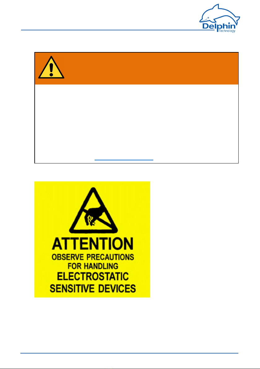
Installing modules, memory card or battery
ElectroniccomponentsaresensitivetoESD(Electro-StaticDischarge).Therefore,
dischargeanyelectrostaticenergybeforeopeningthedevice,forexampletoinstall
anI/Omoduleortoreplacetheintegratedmemorycard.Werecommendwearing
ananti-staticwristband(staticdischargewristband)andtocarryouttheworkon
aconductivesurface.
10
Delphin Technology AG
Dezember 2015
ProfiMessage Manual

ProfiMessage
ESDdamagecanhaveanumberofeffects,fromdeviationinindividualspe-
cificationstototaldevicefailure.
1.2 System requirements
Toensuretrouble-freeoperationoftheDelphinproducts,ensurethatthehard-
warerequirementslistedbelowaremet.
lOperatingsystem
MicrosoftWindowsVista,Windows7,Windows8,WindowsServer2008R2
in32-bitor64-bitversionsandWindows10,eachineitherEnglishorGer-
maneditions.
Werecommendusinga64-bitversion.
lMainmemory
Atleast2GB;
Recommended:3GBfor32-bitsystems,8GBfor64bitsystems
lScreen
Resolutionatleast1024×768pixels,96DPIfixedfontsize(100%)
lCPU
AtleastonePCwith2GHzclassdualcoreprocessor
Recommended:Systemwithquadcoreprocessorfrom3GHz
lHarddisk
ForProfiSignal-Goatleast150MBfreeharddiskspace
ForProfiSignal-Vieweratleast150MBfreeharddiskspace
ForProfiSignal-Klicksatleast1000MBfreeharddiskspace
ForotherProfiSignalversions,atleast500MBfreeharddiskspace
1.3 Symbols used
Tomakereadingthishelpeasierforyou,weusethefollowingsymbols:
Tomakereadingthismanualeasierforyou,weusethefollowingsymbols:
WARNING!
This symbol warns of a potential hazard which - if the
safety requirements are not followed - may be fatal or
cause serious physical injury.
Indicates important inform-
ation.
11
Delphin Technology AG
Dezember 2015
ProfiMessage Manual

ProfiMessage
Info
Referstoaspecialoptionorexplainsaninterestingfea-
ture.
Weuseitalicstoemphasiseindividualtermsinthetext.Wealsohighlightkey-
boardinputstobemadebyyou.Wehavehighlightedthemenususedinthepro-
gramingrey,thearrowsindicatethecorrespondingsubmenus,tobecalled:
Connect→ AddDelphindevice.Titlesofdialogueboxes,allbuttons,andcheck-
boxes,andinputfieldnames,andsoon,areallsohighlightedingreyandaddi-
tionallyidentifiedusingitalics:Display status.Userinputsareinmostcases
illustratedwithexamplesandhighlightedinyellow:Use192.168.10.3astheIP
address.
Wehopethatthishelpsyoutomorequicklyidentifythecorrespondingfields,but-
tons,andmenus,andtolocatetheseintheprogram.
Device labelling
CEsymbol:TheCEsymbolguaranteesthatourproductsmeettherequirementsof
relevantEUdirectives.
12
Delphin Technology AG
Dezember 2015
ProfiMessage Manual

ProfiMessage
2 Getting started
Thissectionoutlines:
lHowtoestablishaconnectionbetweenaPCandthedevice.
lThesettingsrequiredtoacquiremeasurementsignalsfromthedevice.
FordetailedinformationseetheseSections:
lTheSectionProfiMessagedisplaysandconnectionsgivesyouanoverview
ofalltheinterfaces/connections/portsandLEDs.
lTheSectionConfigurationandoperationexplainsthedifferentoptionsforset-
tingupthedeviceformeasurementtasks.TheSectiondescribesspecificset-
tingsforProfiMessagedevices.Theavailablesettingsforalldevicesare
availableunderCommondevicesettings.
SeealsoConfigurationandoperation.
lTheSectiononExamplesofconnectionsshowsyoutheoptionsforcon-
nectingstandardsensorsandactuatorsandhowtoconfigurethem.
lTheSectiononMeasurementtechnologynotescontainsgeneralinformation
andrecommendationsonapplyingmeasurementtechnology.
lTechnicaldataisavailableintheSectiononTechnicalspecifications.
2.1 Installing programs
You need administrator rights to install the pro-
gram.
InstalltheProfiSignalCD.Duringtheinstallation,ensurethatyouinstallthe
DataService Configuratorasaprogram(andnotasaservice).
Afterdefaultinstallationyouwillfindbothofthesesymbolsonyourdesktop:
TheprogramworksDataServiceConfiguratorfromDelphinasalinkbetweenthe
PCandthemeasuringhardware.AlldevicesareimmediatelyconfiguredinDataSer-
viceConfigurator.
TheProfiSignalprogramevaluatesanddisplaysmeasurementdata.
13
Delphin Technology AG
Dezember 2015
ProfiMessage Manual

ProfiMessage
Note for administrators
FortheconnectionbetweenPCandthedevice,youmustenableat
leastports80and1033.
2.2 PC connection
FortheconnectionbetweenPCandthedevice,youmustenableports80and
1033.IfyouuseWindowsfirewall,youmayseeawarningmessagewhenyouadd
theconnection,andauserwithadministratorrightswillneedtoauthorisethecon-
nection.
SeealsoXMLnetworkconfigurationtemplate,LANconnection
Preparing the device to PC connection
lConnectyourPCandthedeviceusingtheEthernetcrossovercablesupplied.
AlternativelyyoucanconnectthedeviceandPCalsoviaanetworkhubor
switch.
Establish device connection
1. StarttheDataServiceConfiguratorprogram,tocreatetheconnectionand
maketheconfiguration.
TheDataServicestartsandtheConnectionstabisdisplayedontheleft-hand
sideintheDataServiceConfigurator.
2. SelectmenuitemConnect→ FindDelphindeviceonLAN.Also,asshownin
theimage,youcanusetheAdddriver(connection)contextmenuinthe
DataServiceentryontheleftofthewindow.
3. Thedevicesearchtakesplaceandadialoguewiththefounddevice(s)isdis-
played.
14
Delphin Technology AG
Dezember 2015
ProfiMessage Manual

ProfiMessage
4. IntheAddcolumn,enablethedeviceordevicesthatyouwanttoconnectto.
ThenclickAdd.
IfthedeviceIPaddressdoesnotcorrespondwiththatofyourPC,youmust
firstassignadifferentnetworkaddress.Ifnodevicesarefound,forexample
ifthescanrequiredforsearching(port16555)isnotpermittedinthenet-
work,youcaneithertryadirectconnectionwithyourPC(withnonetwork)
orthemethoddescribedbelowfordirectconnectionwithPCandfixed
address.
5. Ifthedevice’sUsermanagementisenabled,youwillseeanadditionaldia-
logue.Here,underusernameandpassword,enteryourlogindata.
ThesuccessfulconnectionisthendisplayedwithIPaddressandstatus.The
informationintheDataService...line,Host/IPcolumnisthehostnameorIP
addressofyourPC.
Set different network address
IfthedeviceIPaddressdoesnotcorrespondwiththatofyourPC,afteradevice
searchyouwillbeabletochangetheaddress,beforeyouconnecttothedevice:
EnterasuitableIPaddresscorrespondingtoyourPCIPaddress(similarbutnot
thesame)andsubnetmask.Foranewdevice,usetherootuser,usernameand
passwordarethenonlyrelevantifyouhaveenabledUsermanagementonthe
device.EntertherequireddataandclickOK.Thesettingsaresavedandyouwill
needtocarryoutanewsearch(clickonUpdate).
AlternativelyyoucanalsochangetheIPaddressusingthetouchdisplay:clickon
Networkandthenonthenumbertobechanged.Usingthekeysaboveorbelow
thenumbers,youcanincreaseordecreasethedisplayednumbers.
AthirdoptionisconfigurationviaanyInternetbrowser:
1. LaunchyourInternetbrowserandintheaddressbarenterhttp://andthe
currentdeviceaddress,forexamplehttp://192.168.251.252.
Thedeviceconnectionisestablishedandthehomepageisshown.
15
Delphin Technology AG
Dezember 2015
ProfiMessage Manual

ProfiMessage
2. IntheSettingssection,clickonNetwork.
Thepagewiththenetworksettingsisdisplayed.
3. EnterthedesirednewaddressforyournetworkinIP address.Youcanalso
specifysubnetmaskandgatewayorDNSandNTPserver,seeConfiguration
viaanInternetbrowser.
4. FinallyclickonSavetosaveyoursettings.
Direct connection with PC and fixed address
Ifyournetworkdoesnotallowscanning(port16555notenabled),thenthe
DataServiceConfiguratorcannotfindthedevice.Inthiscaseyouwillneedtoestab-
lishadirectconnectionbetweenthePCanddevice,andsetthePCtothedevice
addressrangeinordertobeabletomakeaconnection.Whileyouhaveacon-
nection,youcansetyourdeviceaddresstoonethatissuitableforyournetwork,
asdescribedabove.Ports80(connectionviawebbrowser)and/or1033(con-
nectionviaDataServiceConfigurator)mustbeenabledfortheTCPprotocol.
TheDelphindeviceIPaddressisidentifiedatthefactorywithasticker.Ifthe
stickerhasbeenlostduringtransportandcannolongerbefound,pleasesearch
foritusingIPaddress192.168.251.252(netmask:255.255.240.0).
(Temporarily)setyourPCtoadifferentaddressinthesameIPsegment:
1. Openthedialogueforyournetworkconnections.
2. Dependingontheoperatingsystem,openthedialogueeitherviatheWin-
dowsStartbuttonandNetworksettingsorviatheControlPanelandNetwork
andSharingCenter.
3. Displaytheconnection(interface)Propertiesviawhichyouwanttoconnect
thedevice(normallycalledLANconnection).InWindowsVistaandinWin-
dows7,clickonShow status,andthenonProperties.
16
Delphin Technology AG
Dezember 2015
ProfiMessage Manual

ProfiMessage
4. DisplaytheInternetprotocolProperties.
5. InthefollowingdialogueyoucaneitherenterafixedaddressforyourPCor–
ifthePCissettoDHCPandtobeusedintheLAN–usetheoptionofspe-
cifyinganAlternative configurationforcaseswherethenetwork(server)is
unavailable(recommendedprocedure).
17
Delphin Technology AG
Dezember 2015
ProfiMessage Manual

ProfiMessage
6. Enteranaddressthatiswithinthesamesegmentasthedeviceaddress(see
abovefigureforanexample).Alsosetthesubnetmask.
7. ClosethedialoguewithOK.
Thentryagaintomakeaconnectionwiththedevice.However,pleaseusethe
Connect→ AddDelphindevicemenutodothis,andenteryourdevicetype.
8. EntertheIPaddressofthedeviceinthedialogue,forexample
192.168.251.252.
9. Ifthedevice’sUsermanagementisenabled,enteryourlogindataunder
Username andPassword.
10. Fortimesignalsandspectra,youhavetheoptiontocompressacquiredmeas-
urementvalues.Compressionreducesmemoryrequirementssignificantly
andcomeswithlosses.
18
Delphin Technology AG
Dezember 2015
ProfiMessage Manual

ProfiMessage
Note:Compressioncancausethemin/maxcharacteristicvaluestonot
exactlymatchthetimesignalorspectrum.
11. ClickOKtocreatetheconnection.
12. Whileyouhaveaconnection,setyourdeviceaddresstoanIPaddressthatis
suitableforyournetwork,asdescribedabove.Howeverdonotforgettoreset
yourPCtotheoriginaladdress.
Offline configuration
IfyouwanttoworkwithasavedConfigurationoffline,selectConnect→ AddDel-
phindeviceandyourdevicetype.
EnableOffline configurationandenterthepathandfilename,orclickonSelect,to
searchforthefile.
Theconfigurationfileisloadedandthedevicecontainedinitisshowninthechan-
neltreeasaphysicallyavailabledevice.
All changes you make to the configuration are saved dir-
ectly in the configuration file.
ToconnectviaXML,youmustenableport1035forTCP(XiMP),and
toconnectviaWebsocketyoumustenableport1036forTCP
(WiMP).
ReferalsotoMainsettings:services.
2.3 Starting the device
Justafewstepsarerequiredtostartusingthedevice:
lUnpackthedevice.
lSchließenSieandiedreipoligeAnschlussklemmeeinegeeigneteSpan-
nungsversorgunganundsteckenSiedieseninBuchse„Power“amGerät..
SieheauchProfiMessage-AnzeigenundAnschlüsse
Theplugisnon-interchangeableandpolarity-protectedandcanbeinserted
intothesocketinonlyonedirection.
Thenextstepsare:
lInstallingprograms
lPCconnection
lBasicsettings
2.4 Starting the ProfiMessage device
JustafewstepsarerequiredtostartusingtheProfiMessagedevice:
19
Delphin Technology AG
Dezember 2015
ProfiMessage Manual

ProfiMessage
lUnpackthedevice.
lPlugthethree-pinned,greyplugfromthesuppliedACadapterintothe
socketmarked‘Power’onthedevice.
referalsotoProfiMessagedisplaysandconnections
Theplugisnon-interchangeableandpolarity-protectedandcanbeinserted
intothesocketinonlyonedirection.
lonlyProfiMessage:
Plugthesuppliedthree-pinnedgreyconnectorfortheexternalbusterminal
inthesocketmarked‘Ext.BUS’.
Theterminalpossessesaresistancethatisnecessaryfortheproperfunc-
tioningofthebussystem.Theresistanceisrequiredevenwhenabus
(cable)isnotconnected.
lConnectthepoweradapterintothemainssocket.
Thenextstepsare:
lInstallingprograms
lPCconnection
lBasicsettings
2.5 Basic settings
Thedialogissplit enabling a device to be selected on the left under Connections
and settings to be made on the right under ChannelsDataServiceConfigurator.
Displaying measurement data
Onceaconnectionhasbeenestablished(seethepreviousSection)currentmeas-
urementdatacanthenbedisplayed.Doubleclickontherightsideonyourdevice
andthenonI/O ChannelsorI/O module(on/ProfiMessage),toopentheentry
anddisplayallavailablechannelsorchannelgroups.TheValuecolumncon-
tinuouslyupdateswithnewmeasurementdata.TheValuecolumncontinuously
updateswithnewmeasurementdata.
Displaying scaled measurement data
Toconvertdatafromthesensorintotherequiredmeasurementunitrequirescon-
figurationofthechannel.Thisallowsthesensormeasurementdatatobescaled
accordinglyorcorrected.RightclickachanneltodisplaythePropertiesdialog.A
generalexplanationofdialogsisavailableundertheSettingsforalldialogsSec-
tion.Specialsettingsfordifferentchanneltypes(analogueinput,analogueoutput)
canbefoundinsubsectionsoftheConfiguringchannels(sensors)Section,orfor
/ProfiMessageunderConfiguringI/Omoduleschannels.Thedialogalsodisplays
connectiondiagrams.UnderI/Omoduleconnectionterminalblocksyouwillfind
theterminalassignmentsfortheI/OmoduleoforProfiMessage.
Other settings
20
Delphin Technology AG
Dezember 2015
ProfiMessage Manual
Table of contents
Popular Test Equipment manuals by other brands

Agilent Technologies
Agilent Technologies 1100 Series user guide

ChemInstruments
ChemInstruments PT-2000 operating instructions

Keithley
Keithley 8011 Connection instructions

Monitech Interlock Systems
Monitech Interlock Systems QuicTest QT-1 Operator's manual

VWR
VWR Peqlab Cast-It instruction manual

Megger
Megger TRS1 user manual


