ChemInstruments PT-2000 User manual

PROBE TACK TESTER
MODEL PT-2000
OPERATING INSTRUCTIONS
CHEMINSTRUMENTS
510 COMMERCIAL DRIVE
FAIRFIELD, OHIO 45014
(513) 860-1598
www.cheminstruments.com
Revision 1.0
August 13, 2019

2 | P a g e
Probe Tack Tester Operating Instructions (PT-2000)
CONTENTS
PRODUCT DESCRIPTION ............................................................................................. 3
SPECIFICATIONS ................................................................................................ 3
UNPACKING ................................................................................................................... 4
ASSEMBLY ..................................................................................................................... 5
KEY COMPONENTS ...................................................................................................... 6
TOUCH SCREEN FORMAT ................................................................................. 8
THEORY OF OPERATION ........................................................................................... 11
POWER UP ........................................................................................................ 11
MACHINE SETUP .............................................................................................. 12
RUNNING A TEST ............................................................................................. 17
DWELL TIME MEASUREMENT ......................................................................... 18
EZ DATA SOFTWARE SYSTEM .................................................................................. 19
MAINTENANCE ............................................................................................................ 21
TROUBLESHOOTING ....................................................................................... 21
MAINTENANCE PROCEDURES ....................................................................... 21
CLEANING THE TOUCH SCREEN ................................................................... 22
LOAD CELL REMOVAL ..................................................................................... 23

3 | P a g e
Probe Tack Tester Operating Instructions (PT-2000)
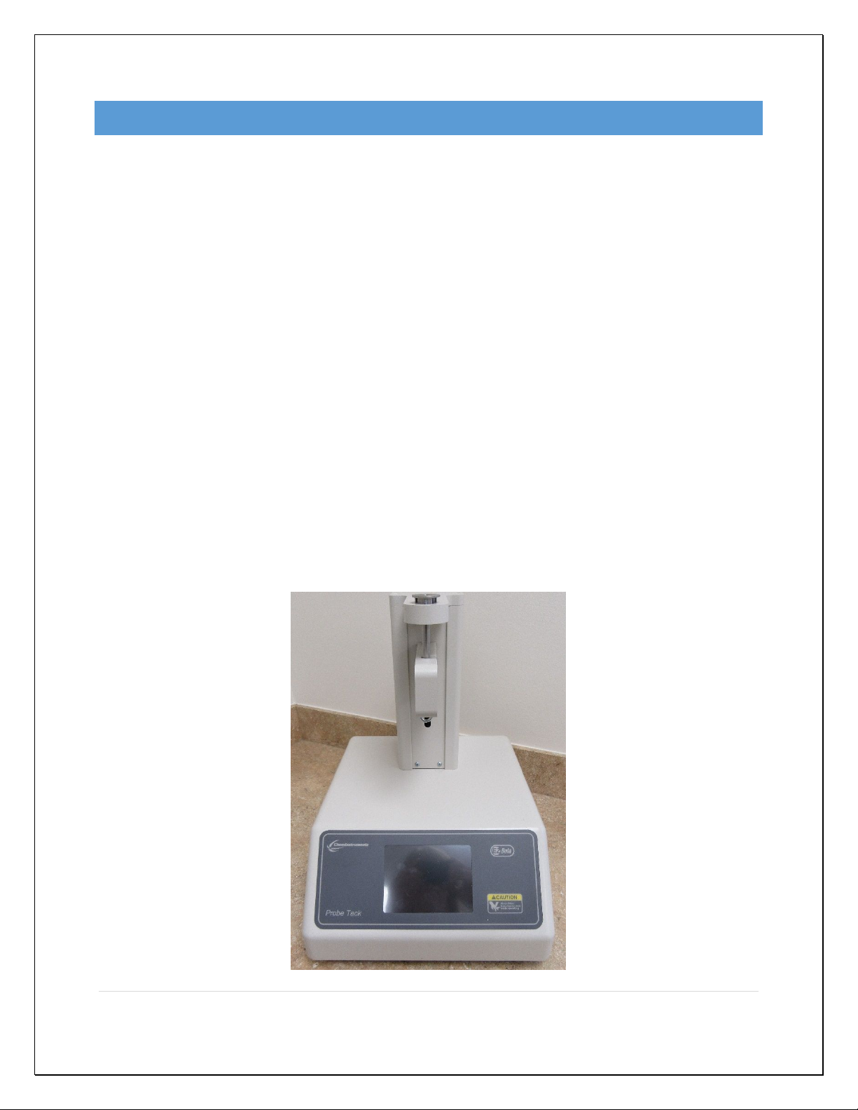
PRODUCT DESCRIPTION
Congratulations on the purchase of your new ChemInstruments Probe Tack Tester.
This versatile, user-friendly, carefully designed instrument allows you to determine
probe tack values of adhesive laminates.
WARNING: This equipment can cause injury if not used properly. It is
the operator’s responsibility to observe all safety rules and warnings.
The unit has the following features:
Automated test sequence.
Collected test data can be exported via USB port.
Selectable units of measure: Kilograms, Grams, Newtons, Pounds, and Ounces.
Compatible with EZ Data System software. See www.cheminstruments.com for
details.
SPECIFICATIONS
Electrical 120/240 VAC, 50/60 Hz, 2 amps
Operating Temperature
32 – 122 degrees Fahrenheit (0 – 50 degrees Celsius)
Humidity 0 – 55% relative humidity
Speed 6 - 30 inches/minute, 1 IPM increments
2 - 12 millimeters/second, 1 mm/sec increments
Dwell Time 1 – 30 seconds, 1 second increments
Probe Diameter 5 millimeter
Annular Ring 19.6 grams
Physical Dimensions Width: 13 inches (33 centimeters)
Depth: 16 inches (41 centimeters)
Height: 18 inches (46 centimeters)
Weight: 25 pounds (12 kilograms)
4 | P a g e
Probe Tack Tester Operating Instructions (PT-2000)
UNPACKING
ChemInstruments has made every effort to ensure that the Probe Tack Tester arrives at
your location without damage. Carefully unpack the instrument and check for any
damage that may have occurred during shipment. If any damage did occur during
transit, notify the carrier immediately.
The ChemInstruments Probe Tack Tester consists of the following parts:
The test frame, which includes the motor/drive mechanism and the data
acquisition system.
Probe and annular ring
An envelope with this manual.
Power cord.
Make sure all of these components are present before discarding packaging material.

5 | P a g e
Probe Tack Tester Operating Instructions (PT-2000)
ASSEMBLY
Carefully remove the test frame/data acquisition assembly from the packaging and set it
on a sturdy bench top. Check the physical dimensions listed previously for the space
required for the instrument. As with any precision piece of laboratory equipment, it is
preferable to locate the Probe Tack Tester in an area where temperature and humidity
are controlled to standard conditions of 72 ± 2 degrees Fahrenheit and 50 ± 5% relative
humidity.
WARNING: Damage will occur if this unit is plugged into the incorrect
power supply. This is a dual voltage machine. Connect either 120 or 240
VAC.
Insert the annular ring in the test platform. Attach the probe to the threaded bolt on the
load cell.
Connect the power cord to its receptacle on the backside of the control cabinet.
Complete the connection by inserting the male end of the power cord into an
appropriate AC outlet. Notice that the on/off power switch is located directly beside the
power cord receptacle on the backside of the test frame.

6 | P a g e
Probe Tack Tester Operating Instructions (PT-2000)
KEY COMPONENTS
POWER SWITCH is located on the back panel of the control cabinet directly
beside the power cord connection.
USB CONNECTION data output port for downloading test data.
ANNULAR RING holds test material
PROBE is used in measuring the force values of the test material
LOAD CELL ASSEMBLY consists of the mounting bracket for the load cell with
grip.
CALIBRATION HOOK is used to hang the weights during the calibration
procedure.
AC Power Input & Switch USB
Annular Ring
Probe
Calibration Hook
Load Cell Assembly
7 | P a g e
Probe Tack Tester Operating Instructions (PT-2000)
TOUCH SCREEN DISPLAY is the control center for the PT-2000.
8 | P a g e
Probe Tack Tester Operating Instructions (PT-2000)
TOUCH SCREEN FORMAT
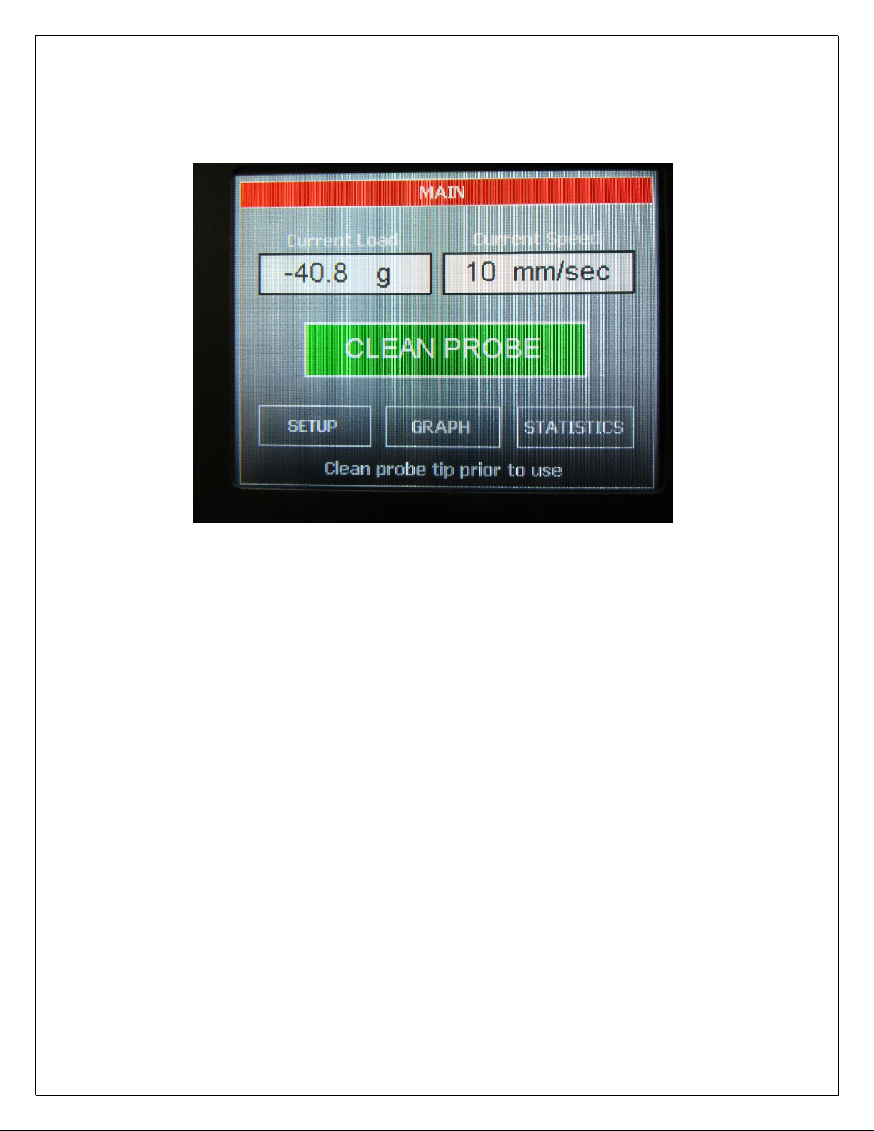
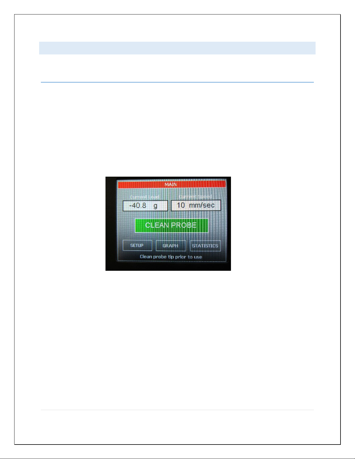
MAIN SCREEN
Current Load – displays the force currently measured by the load cell.
Current Speed – displays the set speed of the test.
Clean Probe – will move the probe to a position so that it may be cleaned prior
to running a test.
Setup – will display all setup options.
Graph – will display the graph, minimum, maximum, and average values of the
last test.
Statistics – will display the minimum, maximum, average, variance, standard
deviation, and work of the last test.
9 | P a g e
Probe Tack Tester Operating Instructions (PT-2000)
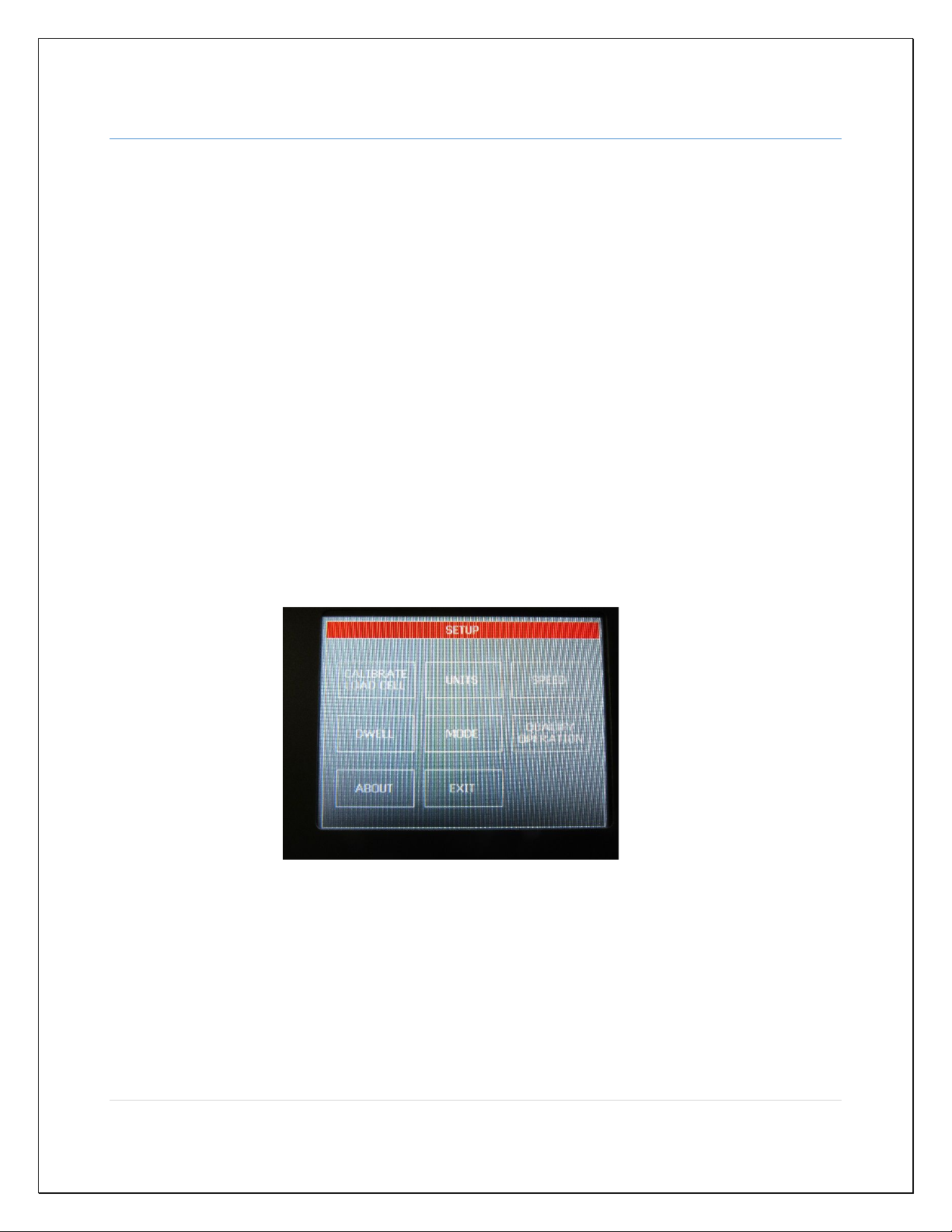
SETUP SCREEN
Calibrate Load Cell – allows the user to calibrate the load cell.
Units – change the force units and/or the speed units.
Speed – set the test platform’s test speed. If the mode is set to D 2979 then
speed is set to 24 in/min (or 10 mm/sec) and cannot be changed.
Dwell – is used to select the dwell time. If the mode is set to D 2979 then dwell
time is set to 1 second and cannot be changed.
Mode – sets the mode of test operation. D 2979 will set the speed and dwell
time specified in the test specification and will not allow the user to change these
two settings.
Qualify Operation – is used verify some of the hardware functions with the PT-
2000.
About – retrieve the machine’s software version and control board’s hardware
revision.
Exit – go back to the main screen.
If there are 30 seconds of no screen activity when in any of the setup screens except
the qualify operation screen, then the machine will exit the setup screen and return to
the main screen.

10 | P a g e
Probe Tack Tester Operating Instructions (PT-2000)
GRAPH SCREEN
The graph screen will display the graph, minimum, maximum, and average values of the
last test. Touch anywhere on the screen to exit the graph screen and return to the main
screen.
STATISTICS SCREEN
The statistics screen will display the minimum, maximum, average, variance, standard
deviation, and work of the last test.
Table of contents
Other ChemInstruments Test Equipment manuals


