manuals.online logo
Brands
  1. Home
  2. •
  3. Brands
  4. •
  5. AFL
  6. •
  7. Test Equipment
  8. •
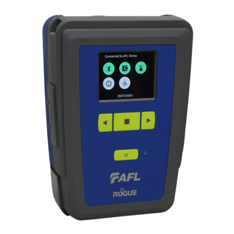
  9. AFL ROGUE cB1 User manual

AFL ROGUE cB1 User manual

1
# Feature Description
1 Strap Eyelet Used to attach an adjustable carry strap.
2 Mini-USB
Function Port
May be used for remote control of the device.
3 USB Host Port Allows connection to USB devices.
4 Key Slot Used to mount a Kickstand accessory on the ROGUE cB1.
5 Touch Screen
Display
Contains on-screen controls and menus; allows to select
parameters/functions and control the operation of the cB1.
6 Function Buttons Used to perform specic tasks. The functionality of these
buttons depends on the active test mode/screen.
7 Power Button Press and hold (~2 seconds) to turn power on or off.
3
7
2
8
4
6
5
1
ROGUE®Device Quick Reference Guide
Test & Inspection
13
9
ROGUE cB1 Device Hardware Overview
11
12
10
For best operation, please update all software upon receipt of equipment.
• For cB1 units, use the “Check for Updates” function in your smart device app
(i.e. TURBO or Linkmap).
• For iB1 units, go to the “AFL store” found on the main screen.
2
# Feature Description
8 AC/Charger
Indicator
When ON, indicates that an AC adapter is connected to
the ROGUE cB1 device: Red light - rechargeable battery is
charging; Green light - rechargeable battery is fully charged.
9Guide Rails Used to mount a Module on the ROGUE cB1.
10 Slot for Module This slot accepts one of the ROGUE Modules.
11 Module Interface
Connector
This connector interfaces with a test module providing
power and passing control and data signals between the
cB1 and module.
12 Battery
Compartment
Holds removable/rechargeable Li-ion battery.
13 AC/Charger Port This is an interface for the AC power adapter/charger.
ROGUE cB1 device can simultaneously operate and charge the internal battery while
connected to the provided AC adapter/charger. To connect the AC adapter/charger:
Battery Charging and Operation - ROGUE®cB1 Device
C
• Plug the AC adapter/charger into a
standard wall outlet.
• Connect the AC adapter/charger to the
power port
A
.
– The AC/Charger indicator
B
turns
RED while battery is charging.
– The AC/Charger indicator turns
GREEN when battery is fully charged.
The battery icon on the ROGUE cB1 device
display
C
indicates the battery status and
shows percentage of the remaining battery
charge as follows:
– Green = >50%,
– White = 20% - 50%,
– Red = <20%
A
B
3
ROGUE®cB1 Device Touch Screen Display Features
1
45
3
# Icon Function
1Bluetooth Connectivity - Pressing this icon will display the
Bluetooth pairing screen. Color code indicates pairing status:
Red = Bluetooth off.
Red Pulsating = Paired; waiting for connection to the App.
Green = Paired with a smart device and the TURBO™App is running.
2Module Info - Pressing this icon will provide information on the
serial number and description of the installed module. Color code:
Red = Module is not connected.
Green = Module is connected.
3Battery/Power Level - This icon will indicate current charge level.
Color code:
Green = >50%
White = Between 20% and 50%
Red = <20%
4ROGUE cB1 Information - Pressing this icon provides options to
display the following information: Module Version (if installed), cB1
Version, Legal Information.
5VFL port - Only present if the installed Module has a VFL port.
Color code:
White = VFL port is Off.
Green = VFL port is On.
Flashing Green = VFL is On/Pulse.
2
4
Installing a Module into ROGUE®cB1 Device
1. Starting from the cB1 top, align bottom of the Module guiding tracks
A
with
top of the cB1 guiding tracks
B
.
2. Slide the Module into the cB1 base.
3. Make sure that Module is completely inserted in the Module Slot.
4. To secure Module, depress the two latch pins until fully seated
C
.
5. Align Kickstand guiding tracks
D
with the cB1 base key slots
E
.
6. Slide the cB1 with mounted Module into Kickstand until fully seated.
1
2
3
4
5
6
2 3 5
1
A
B

6
1. For stationary use, ip-out the Kickstand
handle
F
and position the assembled
ROGUE tester vertically on a at surface.
7
4
C E
F
D
5
ROGUE®iB1 Device Hardware Overview
# Feature Description
1 Strap Eyelet Used to attach an adjustable carry strap.
2 USB Ports
Compartment
Contains the following ports:
• Mini-USB Function Port, which may be used for remote
control of the device
• USB Host Port, which allows connection to USB devices
3 Kickstand Kickstand accessory mounted on the ROGUE iB1. Used for
portrait or landscape positioning.
4 Touch Screen
Display
Contains on-screen controls and menus; allows to select
parameters/functions and control the operation of the iB1.
5 Function Buttons Used to perform specic tasks. The functionality of these
buttons depends on the active test mode/screen.
6 Power Button Press and hold (~2 seconds) to turn power on or off.
7 AC/Charger
Indicator
When ON, indicates that an AC adapter is connected to
the ROGUE cB1 device: Red light - rechargeable battery is
charging; Green light - rechargeable battery is fully charged.
8Guide Rails Used to mount a Module on the ROGUE iB1.
7
3
5
4
1
212
10
11
9
8
6
6
ROGUE iB1 device can simultaneously operate and charge the internal battery while
connected to the provided AC adapter/charger. To connect the AC adapter/charger:
• Plug the AC adapter/charger into a
standard wall outlet.
• Connect the AC adapter/charger to the
power port
A
.
– The AC/Charger indicator
B
turns
RED while battery is charging.
– The AC/Charger indicator turns GREEN
when battery is fully charged.
The battery icon on the ROGUE iB1 device
display
C
indicates the battery status and
shows percentage of the remaining battery
charge as follows:
– Green = >50%,
– White = 20% - 50%,
– Red = <20%
ROGUE iB1 Device Battery Charging and Operation
iB1 may be used in either vertical
or horizontal orientation
# Feature Description
9Slot for Module This slot accepts one of the ROGUE Modules.
10 Module Interface
Connector
This connector interfaces with a test module providing
power and passing control and data signals between the
iB1 and module.
11 Battery
Compartment
Holds removable/rechargeable Li-ion battery.
12 USB/AC Ports
Compartment
Contains USB Host Port (connection to USB devices) and
AC/Charger Port (interface for AC power adapter/charger).
A
B

C
7
1. Starting from the iB1 top, align bottom of the Module guiding tracks
A
with
top of the iB1 guiding tracks
B
.
2. Slide the Module into the iB1 base.
3. Make sure that Module is completely inserted in the Module Slot.
4. To secure Module, depress the two latch pins until fully seated
C
.
5. For stationary operation, use Kickstand handles to position the assembled
ROGUE tester on a at surface. You can choose either portrait (vertical) or
landscape (horizontal) orientation:
– Flip-out one handle for horizontal positioning
D
– Flip-out two handles are used for vertical positioning
E
1
2
3
4
5
5
Installing a Module into ROGUE®cB1 Device
2 3
1
A
B
4
C
D
E
8
For detailed operating instructions on all ROGUE products,
visit www.AFLglobal.com
ROGUE®iB1 Device Touch Screen Display Features
# Icon Function
1Module Info - Pressing this icon will provide information on the
serial number and description of the installed module. Color code:
Red = Module is not connected.
Green = Module is connected.
2Settings - Used to set Wi-Fi, Bluetooth, Sound, Notications and
other common system features.
3Battery/Power Level - This icon will indicate current charge level.
Color code:
Green = >50%
White = Between 20% and 50%
Red = <20%
4ROGUE iB1 Information - Pressing this icon provides options to
display the following information: Module Version (if installed), iB1
Version, Legal Information.
5VFL port - Only present if the installed Module has a VFL port.
Color code:
White = VFL port is Off.
Green = VFL port is On.
Flashing Green = VFL is On/Pulse.
©2017 AFL, all rights reserved. RG1-QRG-1ENG Revision AB, 2017-04-17
1
5
4
2 3

Other manuals for ROGUE cB1

1

Other AFL Test Equipment manuals

AFL MFIS User manual

AFL

AFL MFIS User manual

AFL VFI 2 User manual

AFL

AFL VFI 2 User manual

AFL FlexTester 3 User manual

AFL

AFL FlexTester 3 User manual

AFL FR1 Series User manual

AFL

AFL FR1 Series User manual

AFL FOCIS Lightning 2 User manual

AFL

AFL FOCIS Lightning 2 User manual

AFL FOCIS Duel User manual

AFL

AFL FOCIS Duel User manual

AFL M710 Series Installation instructions

AFL

AFL M710 Series Installation instructions

AFL MLP4-2 User manual

AFL

AFL MLP4-2 User manual

AFL ROGUE cB1 User manual

AFL

AFL ROGUE cB1 User manual

AFL NOYES OLS Series User manual

AFL

AFL NOYES OLS Series User manual

AFL FLX380 User manual

AFL

AFL FLX380 User manual

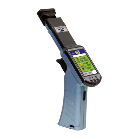
AFL OFI-BI User manual

AFL

AFL OFI-BI User manual

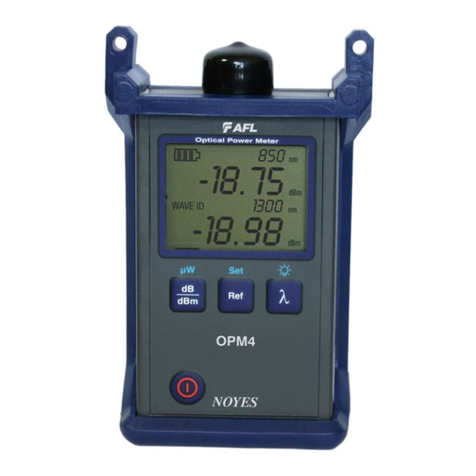
AFL Noyes OPM4 User manual

AFL

AFL Noyes OPM4 User manual

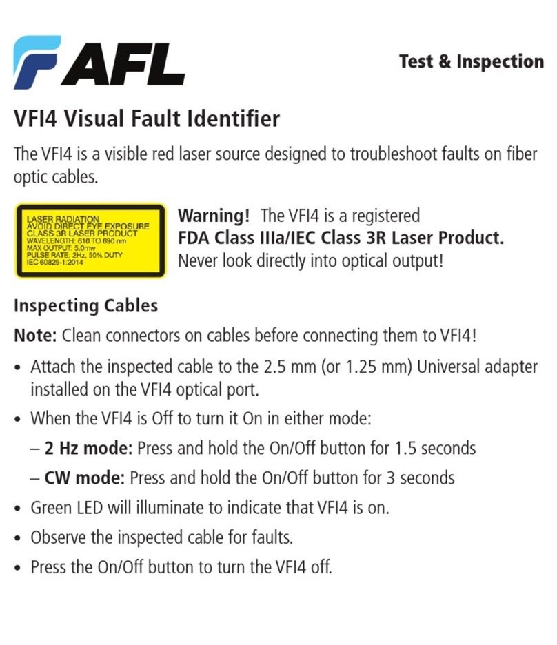
AFL VFI4 User manual

AFL

AFL VFI4 User manual

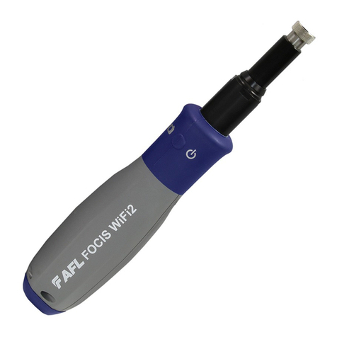
AFL FOCIS WiFi2 User manual

AFL

AFL FOCIS WiFi2 User manual

AFL Noyes OPM4-4 User manual

AFL

AFL Noyes OPM4-4 User manual

AFL FlexScan FS200 OTDR User manual

AFL

AFL FlexScan FS200 OTDR User manual

AFL FOCIS User manual

AFL

AFL FOCIS User manual

AFL FOCIS Lightning 2 User manual

AFL

AFL FOCIS Lightning 2 User manual

AFL FlexScan FS300 User manual

AFL

AFL FlexScan FS300 User manual

AFL Noyes OFI User manual

AFL

AFL Noyes OFI User manual

AFL OPM Series User manual

AFL

AFL OPM Series User manual

AFL Noyes OPM4-3D User manual

AFL

AFL Noyes OPM4-3D User manual

AFL OPM5 User manual

AFL

AFL OPM5 User manual

Popular Test Equipment manuals by other brands

PRESIDIUM Synthetic Ruby Identifier User handbook

PRESIDIUM

PRESIDIUM Synthetic Ruby Identifier User handbook

Sifam Tinsley Zeta 20 user manual

Sifam Tinsley

Sifam Tinsley Zeta 20 user manual

Ritmix RAT-730 Operation manual

Ritmix

Ritmix RAT-730 Operation manual

Hydrajaws M35+ user manual

Hydrajaws

Hydrajaws M35+ user manual

M&A INSTRUMENTS YHT-100 Operation instructions

M&A INSTRUMENTS

M&A INSTRUMENTS YHT-100 Operation instructions

YSI YSI 5905 instruction manual

YSI

YSI YSI 5905 instruction manual

Fluke Hydra Series II user manual

Fluke

Fluke Hydra Series II user manual

BEHA Unitest CHB 7 instruction manual

BEHA

BEHA Unitest CHB 7 instruction manual

Rothenberger ROTEST Electronic 3 Instructions for use

Rothenberger

Rothenberger ROTEST Electronic 3 Instructions for use

Profitec BT 105 A operating instructions

Profitec

Profitec BT 105 A operating instructions

Futech VOLTPEN 200-12 quick start guide

Futech

Futech VOLTPEN 200-12 quick start guide

TriBrer TB-700 user manual

TriBrer

TriBrer TB-700 user manual

AEMC 6470 user manual

AEMC

AEMC 6470 user manual

Bondline SRM3 Instruction Manual Guide

Bondline

Bondline SRM3 Instruction Manual Guide

Sperry instruments CT6101 quick start guide

Sperry instruments

Sperry instruments CT6101 quick start guide

Hanna Instruments pHep+ HI98108 user manual

Hanna Instruments

Hanna Instruments pHep+ HI98108 user manual

METREL Eurocheck CS 2099 user manual

METREL

METREL Eurocheck CS 2099 user manual

Additel 761A user manual

Additel

Additel 761A user manual

manuals.online logo
manuals.online logoBrands
  • About & Mission
  • Contact us
  • Privacy Policy
  • Terms and Conditions

Copyright 2025 Manuals.Online. All Rights Reserved.