Delta Heat DHVH36 User manual

DELTA HEAT VENT HOOD
INSTALLATION INSTRUCTIONS
MODELS: DHVH36
DHVH48
DHVH60
FOR RESIDENTIAL USE ONLY.
P/N: 24388b 05/21

A Special Message to our Customers...
Congratulations on your purchase of Delta Heat Vent Hood. Delta Heat is com-
mitted to making outdoor cooking products you’ll be proud to own for years.
This manual gives you easy to follow instructions for installing, operating and
maintaining your Delta Heat Vent Hood. We recommend reading this manual
carefully before your rst use to ensure safety, proper care and operation.
Thank you and welcome!
Delta Heat

PLEASE READ ENTIRE INSTRUCTIONS BEFORE PROCEEDING.
INSTALLATIONS MUST COMPLY WITH ALL LOCAL CODES.
IMPORTANT: Save these instrucons for the Local Electrical Inspector’s use.
INSTALLER: Please save these Installaon Instrucons with this unit for owner.
OWNER: PLEASE READ AND SAVE THESE INSTRUCTIONS FOR FUTURE REFERENCE.
FOR YOUR RECORDS
Please record the following information and refer to them when contacting the company or
an authorized service agent. This information is found on the data nameplate, located inner
left hand face of the Vent Hood. Remove the leftmost Bae Filter to visually access the Data
Plate.
MODEL #:
____________________________________________
SERIAL #:
____________________________________________
DATE OF PURCHASE:
____________________________________________
PLACE OF PURCHASE:
____________________________________________
Table of Contents
Important Safety Instructions
Getting Started
Electrical Requirements
Vent Hood Knock-outs and Mounting Locations
Top Exhaust
Rear Exhaust
Mounting the Transition
Outside Patio or Lanai Installation
Bae Filter Installation, Use and Care
DHVH Exploded View
DHVH Replacement Parts List
Wiring Diagram
Warranty
How to Obtain Service
1
2
3
4-5
6
7-8
8
9-10
11
12
13
14
15
17

1 | www.deltaheat.com
WARNING: CALIFORNIA PROPOSITION 65
This product can expose you to chemicals including carbon monoxide which is known to the State
of California to cause cancer and reproductive harm. To minimize exposure to the by-products of the
burning fuel or from combustion, always operate this unit according to the use and care manual and
provide good ventilation. California law requires businesses to warn customers of potential exposure
to such substances. For more information go to www.P65Warnings.ca.gov.
AVERTISSEMENT: PROPOSITION 65 DE L’ETAT DE LA CALIFORNIE
Cet appareil peut vous exposer aux produits chimiques et au gaz monoxyde de carbonne reconnue
dans l’Etat de la Californie pour causer le cancer et des problemes de fertilite. Pour minimiser l’expo-
sition de ces-sous produits combustibles ou de la combustion, utiliser toujours cet appareil en con-
formitee au manuel d’utilisation et d’entretien en s’assurant egalement d’une bonne ventilation. La loi
de la Californie exige aux fabricants d’informer leurs clients aux risques d’exposition potentielle a de
telles substances. Pour plus d’information, visiter le site www.P65Warnings.ca.gov
WARNING - TO REDUCE THE RISK OF A RANGE TOP GREASE FIRE:
A. Never leave surface units unattended at high settings. Boilovers cause smoking and greasy spill-
overs that may ignite. Heat oils slowly on low or medium settings.
B. Always turn hood ON when cooking at high heat or when ambeing food (i.e. Crepes Suzette,
Cherries Jubilee, Peppercorn Beef Flambe’)
C. Clean ventilating fans frequently. Grease should not be allowed to accumulate on fan or lter.
D. Use proper pan size. Always use cookware appropriate for the size of the surface element.
WARNING - TO REDUCE THE RISK OF INJURY TO PERSONS IN THE EVENT OF A RANGE TOP
GREASE FIRE, OBSERVE THE FOLLOWING:
A. SMOTHER FLAMES with a close tting lid, cookie sheet, or metal tray, then turn o the burn-
er. BE CAREFUL TO PREVENT BURNS. If the ames do not go out immediately, EVACUATE
AND CALL THE FIRE DEPARTMENT.
B. NEVER PICK UP A FLAMING PAN - You may be burned.
C. DO NOT USE WATER, including wet dishcloths or towels - a violent steam explosion will result.
D. Use an extinguisher ONLY if:
1. You know you have a Class ABC extinguisher, and you already know how to operate it.
2. The re is small and contained in the area where it started.
3. The re department is being called.
4. You can ght the re with your back to an exit.
Read this manual carefully and completely before using your Vent Hood to ensure proper operation,
proper installation, proper servicing and to reduce the risk of re, burn hazard and/ or other injury.
TO REDUCE THE RISK OF FIRE, ELECTRICAL SHOCK, OR INJURY TO PERSONS, OBSERVE
THE FOLLOWING:
A. The installation of this appliance must conform with local codes.
B. Sucient air is needed for proper ventilation of ue gases. Use metal ducting only; no smaller
than 10” diameter. Ventilation must be to the outdoors.
C. When cutting or drilling into wall of ceiling, do not damage electrical wiring and other hidden
utilities.
D. Before servicing or cleaning unit, unplug from GFCI outlet.
WARNING
TO REDUCE THE RISK OF FIRE, USE ONLY METAL DUCTWORK.
Important Safety Instructions
Delta Heat Service (562) 263-3600 | 2
Read this instruction completely before starting installation. Planning the complete installation
before starting work is highly recommended. This includes all aspects of the installation including
hood location, ducting, electrical requirements, and adequacy of mounting surfaces.
1. Remove all packaging materials, labels and protective plastic lm. DO NOT LEAVE UNIT IN THE
SUN WITH PROTECTIVE PLASTIC FILM ON FOR AN EXTENDED PERIOD OF TIME AS IT
WILL BECOME DIFFICULT TO REMOVE.
2. Check to ensure all Vent Hood accessories listed below are included.
3. Assemble parts as per assembly instructions.
4. Fill out Warranty Registration Card and mail it to the indicated address, or register online. See
page 17.
Vent Hood Accessories DHVH36 DHVH48 DHVH60
BAFFLE FILTER 3 4 5
CAUTION:
• To reduce the risk of re and electric shock, install this vent hood only with Integral Blower
TEVI-120I-C.
• The hood is of sucient weight that two installers are recommended to prevent injury or damage
to the hood in handling.
• Hood is recommended for use over domestic gas or electric appliances. Not recommended for
use over solid fuel red appliances.
Getting Started:
The vent hood is operated by a 3-speed rotary control switch located in the front left of the
hood. Medium to low speed will handle most exhaust requirements. Use the high-speed position for
heavy cooktop use conditions. Turn the vent hood on just before cooking to prevent the escape of
discharges from the cooking surface.
The light rotary switch is located to the right of the ventilation control.
OPERATING INSTRUCTIONS:
CLEANING AND MAINTENANCE:
CAUTION: Shut o power to unit at service entrance if you are cleaning the blower.
Use a damp cloth to wipe the outer surface of the blower. Do no use a dripping wet cloth to wipe
blower. Never put your hand int the blower housing.
To clean the hood surface use only mild soap or detergent solutions. Wipe to dry surfaces using a soft
cloth. If a stainless surface is being cleaned, always wipe in the direction of the brush surface.
Cleaning aids such as “Stainless Steel Magic” are available. Never us abrasive cleaners, pads or
cloth.

3 | www.deltaheat.com
Electrical Requirements:
WARNING
GROUNDING INSTRUCTIONS
This appliance must be grounded. In the event of an electrical short circuit, grounding reduces the
risk of electric shock by providing an escape wire for the electrical current. This appliance is equipped
with a cord having a grounding wire with a grounding plug. The plug must be plugged into an outlet
that is properly installed and grounded.
WARNING - Improper grounding can result in a risk of electric shock.
Consult a qualied electrician if the grounding instructions are not completely understood, or if doubt
exists as to whether the appliance is properly grounded.
Do not use an extension cord. If the power supply cord is too short, have a qualied electrician install
an outlet near the appliance.
NOTE:
Ventilator requires a dedicated 15
AMP Power Supply.
The appliance should only be taken apart by a qualied technician, or electrical shock may
occur. It is rated at 120V, 5.4 Amps, 60Hz.
REMINDER:
Keep any electrical supply cord away from any heated features.
Unit comes with three-pronged power cord pre-installed. Vent hood must be plugged into a GFCI
protected branch circuit. Suitable for use in damp locations when installed in a GFCI protected branch
circuit.
HALOGEN LAMP WATTAGE: 40 WATTS PER LAMP
Delta Heat Service (562) 263-3600 | 4
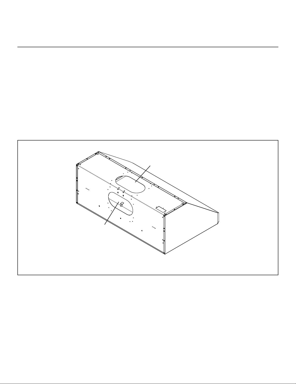
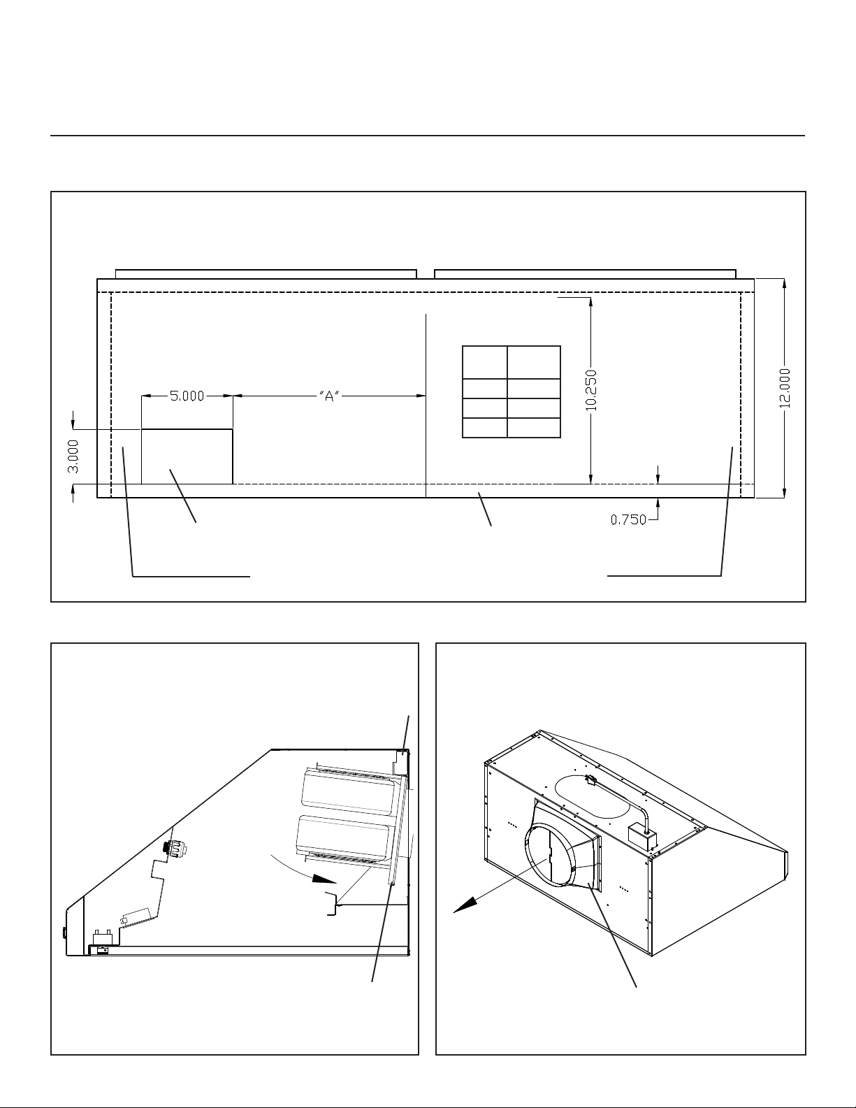
Vent Hood Knock-outs and Mounting Locations:
FIG 1A
1
2
FOR REAR EXHAUST
FOR TOP EXHAUST
UNIT MUST BE VENTED TO THE OUTSIDE OF THE
BUILDING.
!!
NOTE: The hood is of sucient weight that two installers are recommended to prevent injury or dam-
age to the hood in handling.
Before starting the installation, you must identify if the installation will be a rear exhaust or top ex-
haust installation.
Begin the installation by removing the appropriate knock-out that will provide the top or rear exhaust
point. See FIG 1A for knock-out locations.
CAUTION:
When knock outs are removed the
edges will be sharp!!! Sharp edges
should be led or covered with metal
tape.
! !
5 | www.deltaheat.com
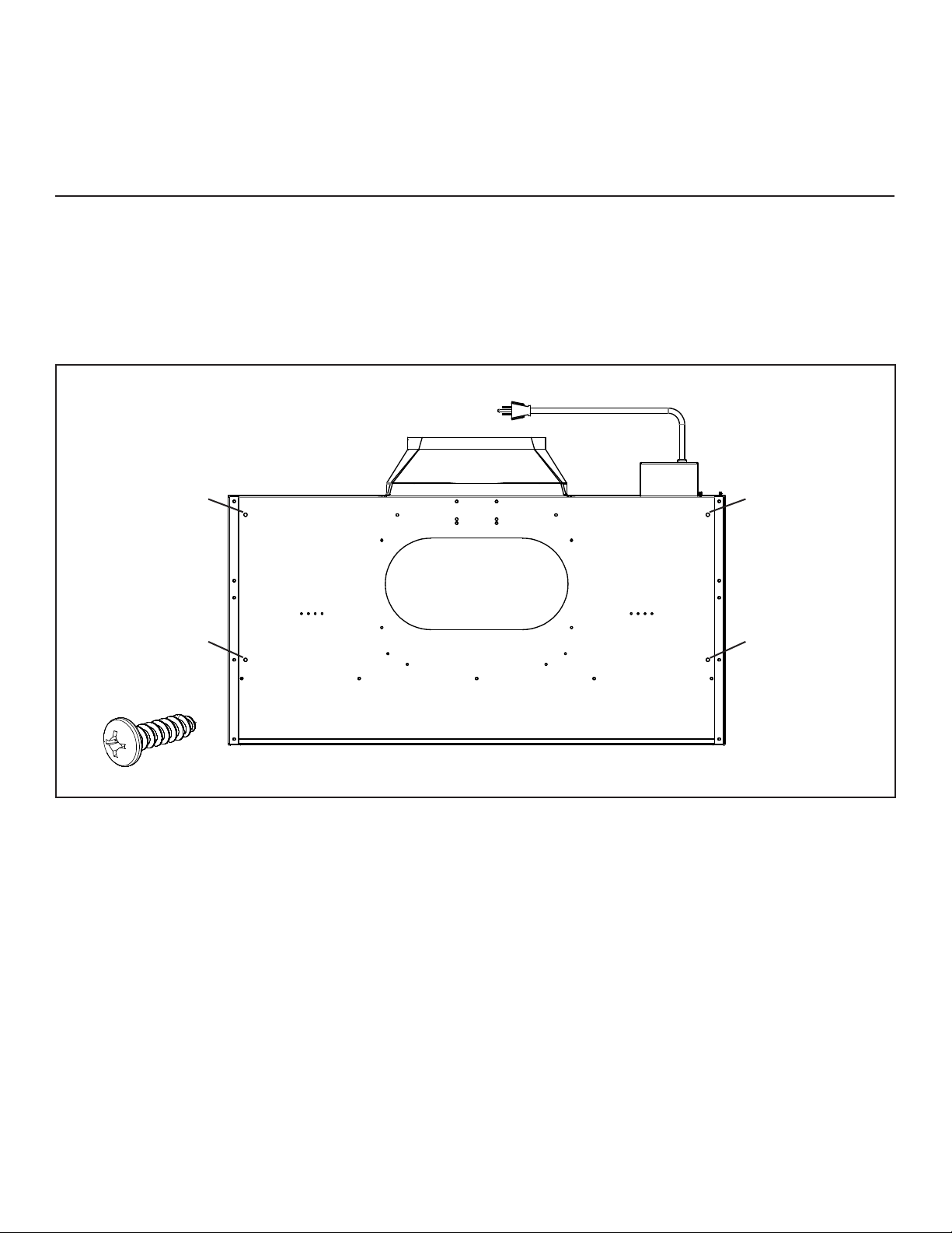
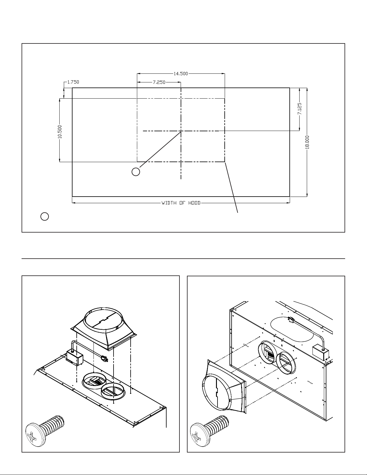
Vent Hood Knock-outs and Mounting Locations -
cont:
FIG 1B
MOUNTING HOLEMOUNTING HOLE
MOUNTING HOLEMOUNTING HOLE
X 4
MOUNTING SCREW
Installation of the Vent Hood should also take into account the unit that the Vent Hood is to be in-
stalled above. For best ventilation of smoke and heat, make sure the vent hoof is centered above the
appliance and a minimum of 36 inches above the cooking surface. Refer back to the appliance manu-
al to be sure distances and clearances to combustible construction are maintained.
Mounting locations are shown in FIG 1B:
Mounting surface must be a minimum of 3/4” thick. Mount Vent Hood to desired construction using
#10 wood screws. A minimum of four #10 wood screws are needed to mount the Vent Hood. Longer
screws may be required if wall board or other nonstructural surfaces are used between the hood and
the main mounting surface. Anchors may be required if mounting screws do not engage the wood
structure.
Use of furring strips to level the cabinet mounting surface may be required. Refer to FIG 2 for ducting
clearances and furring strip locations.
Delta Heat Service (562) 263-3600 | 6
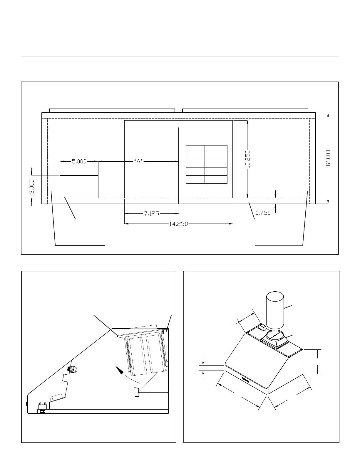
TOP EXHAUST
FIG 2
BOTTOM VIEW OF CABINET
WIRING ACCESS BACK WALL
ADD FURRING STRIPS TO PROVIDE AN EVEN BOT-
TOM SURFACE FOR THE HOOD MOUNTING.
FIG 3
REMOVE KNOCK OUT # 2
ROTATE
INTO
POSITION
& SECURE
WITH 2
SCREWS
B A
10” DISCHARGE WITH TRANSITION WILL BE ON THE
CENTER LINE OF HOOD WIDTH AND ON CENTER LIE
OF 12” DIMENSION.
FIG 4
VERTICAL DISCHARGE
3”
ALL HOODS 30”
18”
12”
10” DUCT TO
DISCHARGE W/
ROOF OF WALL
CAP
TRANSITION
HOOD
WIDTH DIM A
36” 8 3/8”
48” 17 1/2”
60” 23 7/16”
7 | www.deltaheat.com
REAR EXHAUST
ROTATE
INTO
POSITION
& SECURE
WITH 2
SCREWS
FIG 6
A
B
FIG 5
BOTTOM VIEW OF CABINET
ADD FURRING STRIPS TO PROVIDE AN EVEN BOT-
TOM SURFACE FOR THE HOOD MOUNTING.
WIRING ACCESS BACK WALL
FIG 7
SECURE TRANSITION TO HOOD
USING #10 SHEET METAL SCREWS.
TAPE ALL JOINTS AND SEAMS.
ROUTE TO OUTSIDE
WITH WALL CAP
TRANSITION TO 10”
DUCT OR WALL CAP
HOOD
WIDTH DIM A
36” 8 3/8”
48” 17 1/2”
60” 23 7/16”
Delta Heat Service (562) 263-3600 | 8
FIG 8
REAR EXHAUST
CUT HOLE IN DRYWALL TO ACCEPT
TRANSITION
= CENTER OF ROUND DUCT USING
TWIN EAGLES TRANSITION
A
A
MOUNTING THE TRANSITION:
X 4
FIG 9
TOP EXHAUST
FIG 10
REAR EXHAUST
#10-24 METAL CUTTING SCREWS
X 4
#10-24 METAL CUTTING SCREWS
9 | www.deltaheat.com
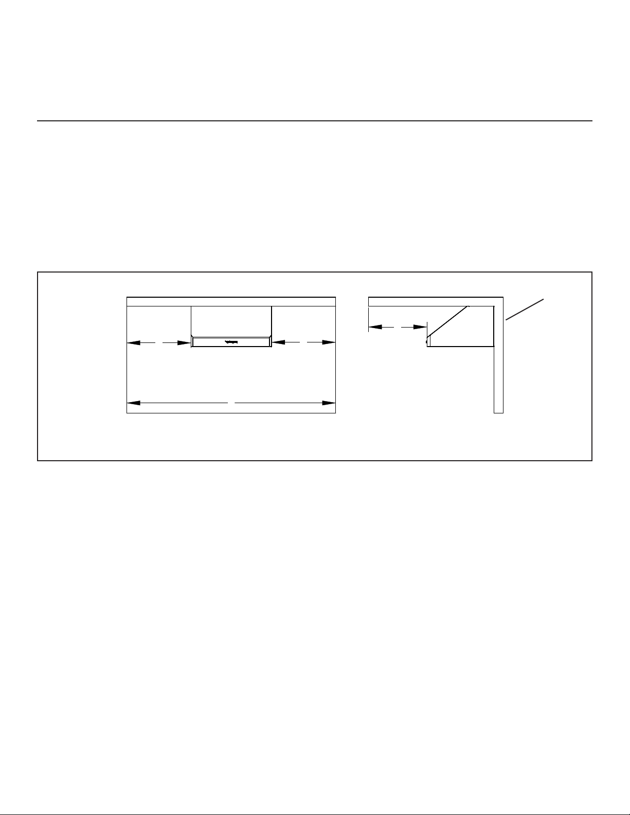
OUTSIDE PATIO or LANAI
INSTALLATION
Construction methods and installation shall comply with all local building codes. Internal
ducting shall be sealed using outdoor rated metal tape.
The Twin Eagles hood with stainless steel canopy is approved for installation in an outside patio or
lanai area if the area is covered with a protective roof over the hood (wall style hoods are to be also
mounted to a solid protective rear wall) and installed with a GFCI protected branch circuit. Roof or
Wall Caps are to be sealed to prevent moisture migration to structure interior; use an outdoor rated
sealant suitable for adhesion to the installation materials. See FIG 6 for rear exhaust installation and
FIG 3 for top exhaust installation.
A A
B
A = 42” MINIMUM
FRONT VIEW
B = 30” MINIMUM
SIDE VIEW
REAR
EXHAUST
*
* = TOTAL OVERALL
WIDTH WITH HOOD
FIG 9 WALL
CAP
The roof shall cover the top of the hood and extend a minimum of 42” from each side of the hood and
30” minimum from the outer edges of the hood front.
Since, outdoor areas are subject to strong cross drafts it is recommended that the hood extend at
least 3 inches and preferably 6 inches, over either side of the cooking area to maximize the cooking
discharge capture area. Cross drafts will aect the eciency of the ventilation system and cooking
discharge can escape capture by the hood/ventilation system. Be sure to plan for adequate ventilator
(blower) capacity to minimize cross drafts inuencing the removal of cooking discharges.
The installation instructions that accompanies the hood shall be followed to ensure all safety instruc-
tions and guidelines are adhered to.
See FIG 10 for structure with elevated roof / ceiling.
Suitable for use in damp locaons when installed in
a GFCI protected branch circuit.

Delta Heat Service (562) 263-3600 | 10
AA
B
A = 42” MINIMUM
FRONT VIEW
B = 30” MINIMUM
SIDE VIEW
TOP
EXHAUST
*
* = TOTAL OVERALL
WIDTH WITH HOOD
FIG 10
ROOF
CAP
12”

11 | www.deltaheat.com
BAFFLE FILTER
INSTALLATION, USE AND CARE
INSTALLER: Please leave these installation instructions with unit for the owner.
1. Remove all packaging and the productive plastic covering from lters.
2. Grasp the lter by the center bae, see FIG 11, with the spring end facing you and the grease
collector channel is facing down and toward the rear of the hood. Position the spring end of the
lter into the upper channel of the front escutcheon, compress the spring by pulling the lter
toward you and rotate the rear of the lter up and into the rear retaining recess formed by the
rear escutcheon and retaining clip. Release the lter, being sure it is positioned properly in the
channels. You should be able to push and pull down on the lter without having it come out of
position. You can bend the spring lightly outward if the lter is no pressing securely against the
rear escutcheon.
3. The lter has an integral grease collector and is dishwasher safe. To clean your lter simply
grasp the lter by its center bae, pull toward the front of the hood and rotate the rear of the
lter down and away from the hood, see FIG 12.
4. For best dishwasher results, position the lters in the dishwasher rack with the baes positioned
horizontally.
BACKDRAFT DAMPER: It is recommended that a backdraft damper in all installations. In cold
weather installations it is necessary to use a backdraft damper to minimize backow of cold air into
the room. A non-metallic thermal break should also be used to minimize conduction of outside tem-
peratures through the ductwork. The thermal break should be located as close as possible to where
the ducting enter the heater portion of the room.
FIG 11
1
2
3
WRONG
GREASE
COLLECTOR
CHANNEL
1. POSITION IN UPPER CHANNEL
2. PULL
3. ROTATE UP AND INTO RETAINING RECESS
FIG 12
1
23
1. PULL
2. ROTATE DOWN
3. REMOVE FILTER
Delta Heat Service (562) 263-3600 | 12
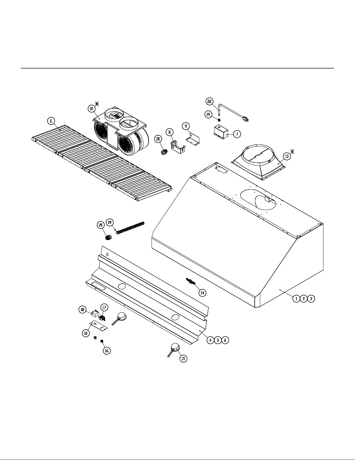
DHVH
EXPLODED VIEW
* - #12 AND #13 SOLD SEPARATELY

13 | www.deltaheat.com
DHVH
REPLACEMENT PARTS LIST
ITEM
NO.
PART
NUMBER DESCRIPTION DHVH36-C DHVH48-C DHVH60-C
1 S21160-36Y 36” VENT HOOD ASSEMBLY 1 - -
2S21160-48Y 48” VENT HOOD ASSEMBLY -1-
3 S21160-60Y 60” VENT HOOD ASSEMBLY - - 1
4 S21166-36Y 36” CONTROL PANEL ASSEMBLY 1 - -
5 S21166-48Y 48” CONTROL PANEL ASSEMBLY -1-
6 S21166-60Y 60” CONTROL PANEL ASSEMBLY - - 1
7 S21167 RECEPTACLE BOX COVER 1 1 1
8 S21171 ELECTRICAL BOX BODY 1 1 1
9 S21172 ELECTRICAL BOX COVER 1 1 1
10 S21173 SWITCH PANEL 1 1 1
11 S21164Y BAFFLE FILTER ASSEMBLY 3 4 5
12* S16477 BLOWER MOTOR ASSEMBLY (SOLD SEPARATELY) 1 1 1
13* S13166 VENT HOOD DAMPER (SOLD SEPARATELY) 1 1 1
14 S19680 DELTA HEAT LOGO 1 1 1
15 S16494 HALOGEN LIGHT 2 2 2
16 S13501 HIGH TEMP CONTROL KNOB 2 2 2
17 S16493 3-POS ROTARY SWITCH 1 1 1
18 S16492 4-POS ROTARY SWITCH 1 1 1
19 S14536-24 HEAVY DUTY FLEXIBLE CONDUIT 1 1 1
20 S14537 HEAVY DUTY CONNECTOR 2 2 2
21 S16112 STRAIN RELIEF 1 1 1
22 S16111Y ELECTRICAL CORD ASSEMBLY 1 1 1
PARTS NOT SHOWN
23 S16482 WIRE HARNESS, VENT HOOD ADAPTER 1 1 1
24 S16496 WIRE HARNESS, LIGHT SWITCH TO BLOWER MOTOR 1 1 1
25 S16497 WIRE HARNESS, RECEPTACLE PLUG 1 1 1
26 S16498 WIRE HARNESS, BM ROTARY HI TO RECEPTACLE PLUG 1 1 1
27 S16499 WIRE HARNESS, BM ROTARY LOW TO RECEPTACLE
PLUG 1 1 1
28 S16501 WIRE HARNESS, BM ROTARY MID TO RECEPTACLE PLUG 1 1 1
29 S16502 WIRE HARNESS, SWITCH TO LH AND RH LIGHT 1 1 1
30 S16503 WIRE HARNESS, SWITCH WITH BRIDGE TO LH LIGHT 1 1 1
31 S16504 WIRE HARNESS, SWITCH WITH BRIDGE TO RH LIGHT 1 1 1

Delta Heat Service (562) 263-3600 | 14
DHVH
WIRING DIAGRAM
W 1 8 GA
BLK 18 GA
BLU 18 GA
R 18 GA
HHOOOODD
RREECCEEPPTTAACCLLEE
BBOOXX
PPOOWWEERRSSUUPPPPLLYY
LL11
BLK 18 GA
GGNN
GR N 1 8 GA
WHT 18 GA
11
AA
22
33
BB
44
RROOTTAARRYY
LLIIGGHHTT
SSWWIITTCCHH
LLEEFFTT
LLIIGGHHTT
RRIIGGHHTT
LLIIGGHHTT
11LLOO
MMEEDD
HHII
66
44
22
33--SSPPDD
RROOTTAARRYY
SSWWIITTCCHH
BBLLOOWWEERR
MMOOTTOORR
WHT 18 GA
BLK 12 GA
BLK 18 GA
BLU 18 GA
R 18 GA
BLK 18 GA
WHT 18 GA
BLK 18 GA
BLK 18 GA
WHT 18 GA
WHT 18 GA
WHT 18 GA
WHT 18 GA
WHT 18 GA
WHT 18 GA

15 | www.deltaheat.com
DHVH
WARRANTY
LIMITED TWO YEAR WARRANTY: Delta Heat warrants the Vent Hood to be free from defects in materials
and workmanship under normal residential use for a period of two years from the original date of purchase.
The actual part will be repaired or replaced, free of charge, with the owner paying for all other costs including
labor, shipping and handling.
ONE-YEAR FULL WARRANTY: Delta Heat warrants the Vent Hood and all other components to be free from
defects in materials and workmanship under normal residential use for a period of one year from the original
date of purchase. Delta Heat will repair or replace parts found to be defective at no cost to the original pur-
chaser. Warranty service must be performed by a Delta Heat authorized representative during normal business
hours.
NINETY (90) DAY RESIDENTIAL PLUS WARRANTY: This warranty applies to applications where use of the
product extends beyond normal residential use such as bed and breakfast inn and private clubs. The actu-
al part will be repaired or replaced, free of charge, with the owner paying for all other costs including labor,
shipping and handling. This warranty excludes all commercial locations such as restaurants and food service
locations.
WARRANTY LIMITATIONS & EXCLUSIONS
This warranty shall apply only to the products purchased and located in the continental United States and Can-
ada. The warranty coverage begins on the original date of purchase and proof of date of purchase is required.
To activate the warranty, we require that you send in the attached warranty registration card. This warranty
applies only to the original owner and may not be transferred.
This warranty excludes discoloration, surface scratches, weather and atmospheric related staining, and minor
surface rust and oxidation which are normal conditions and are to be expected with any outdoor product. This
warranty does not apply to damages resulting from negligence, alteration, misuse, abuse, accident, natural
disaster, loss of electrical power to the product for any reason, improper installation or improper operation,
unauthorized adjustments or calibrations, dings, dents, scratches, or damages due to harsh cleaning chemi-
cals. This warranty does not apply to commercial use, or to products with altered or removed serial numbers.
Display models are generally sold “as is” and are subject to the following warranty exclusions: missing com-
ponents, scratches, dents and other exterior or cosmetic damages, electrical, gas and ignition system. Delta
Heat shall not be liable for incidental, consequential, special or contingent damages resulting from its breach of
this written warranty or any implied warranty.
WARRANTY SERVICE & REPLACEMENT PARTS: Call your authorized selling dealer or call Delta Heat di-
rectly at (562) 263-3600. Be prepared to furnish the following information: Purchaser’s name, model and serial
number of the Power Burner, date of purchase and the accurate description of the problem. Delta Heat will not
pay for service calls for correcting an installation problem. Owner shall be responsible for proper installation,
providing normal care and maintenance, providing proof of purchase upon request and making the side burn-
er accessible for service. In the event of any warranty replacement, all removal, replacement, installation and
shipping costs are the responsibility of the owner.
Some states do not allow limitations on how long an implied warranty lasts, or the exclusions of or limitations
on consequential damages. This warranty gives you specic legal rights and you may have other rights, which
vary from state to state.
Delta Heat Service (562) 263-3600 | 16
For service, please contact your Delta Heat dealer or call Delta Heat direct at (562) 263-3600 or fax
(562) 802-3391
Mailing address:
Twin Eagles, Inc.
13259 East 166th Street
Cerritos, CA 90703
Visit us at www.deltaheat.com
Please provide:
• Model number
• Serial Number (located on the inner left hand face of the vent hood. Remove left most Filter Baf-
e to access Data Plate)
• Date of Purchase
• A description of the problem
WARRANTY REGISTRATION
This warranty registration card must be returned within thirty days of purchase to properly activate
your warranty. This information is for our internal use only.
Or you may register online at https://deltaheat.com/about-us/contact-us/
Customer Name: Model #:
Address: Serial #:
City, State: Date Purchased:
Zip: Dealer’s Name:
Phone #: Dealer’s Address:
E-mail:
SERVICE
HOW TO OBTAIN

Place
Postage
Here
CUT HERE
Customer Service
ATTN: Warranty Department
13259 East 166th Street
Cerritos, CA 90703
Fax no. (562) 802-3391
This manual suits for next models
2
Table of contents
Popular Ventilation Hood manuals by other brands


Jenn-Air
Jenn-Air 30" Installation Instructions and Use & Care Guide

ELICA
ELICA EVR636S1 Use, care and installation guide

Gorenje
Gorenje S1 BHP643A5BG installation instructions

Spagna Vetro
Spagna Vetro UCH18 Pro Turbo Series User instructions

JUNO
JUNO JDA 5330 Instruction on mounting and use

Miele
Miele DA1180 specification