Delta-T Devices WS-GP1 User manual

WS-GP1 Weather Station
WS-GP1 Weather Station for wind speed and direction, relative
humidity, air temperature, rain and solar radiation
Quick Start Guide
Version 2.0
Delta-T Devices Ltd
Page 2 © 2018 Delta-T Devices Ltd
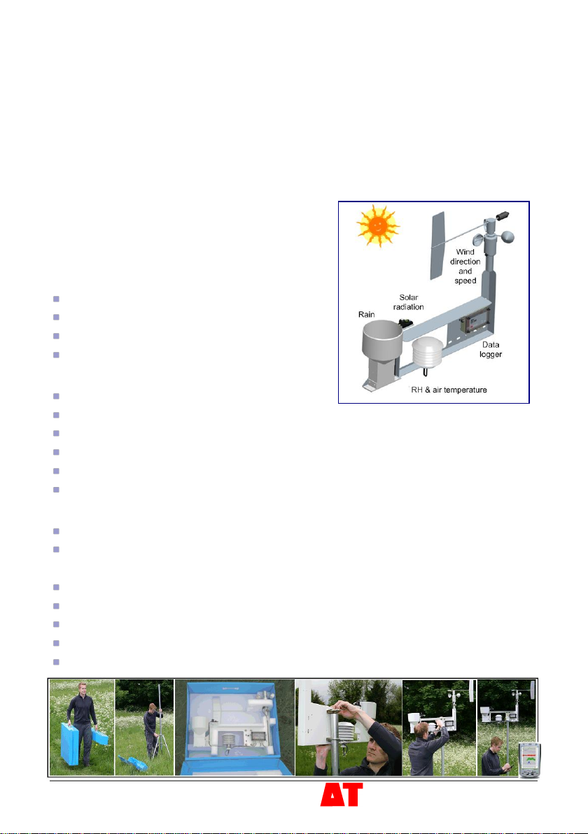
Introduction
The WS-GP1 Weather Station measures wind speed and direction, air temperature,
relative humidity, solar radiation and rainfall.
Apart from the wind vane tail, the sensors are already attached to the cross-arm and
connected to a GP1 Logger with a weather station program installed.
This guide explains how to choose a site, install the mast, mount and align the cross
arm, add the wind-vane tail and align it to North. Then, using a PC or Windows Mobile
Device we show how to change the weather station program, check the sensor
readings, then acquire and display readings.
1Unpacking
Check your contents against your order.
You should have a cross arm fitted with a GP1
logger pre-wired to:
Wind speed and direction sensor D-034B-CA
RH and air temperature sensor RHT3nl-CA
Solar energy flux sensor PYRPA-03
Rain gauge RG2+WS-CA
You should also find the following:
Sensor user manuals
GP1 Quick Start Guide and screwdriver
Allen keys - 5/64 inch for the wind vane and 2.5 mm for light sensor levelling mount
Spanner for the mast
GP1-RS232 serial cable
Delta-T Software and Manuals CD including DeltaLINK PC version 2.3 or later
You may also have the following:
Tripod mast M2-TRPD or some other mast to mount on
Guy wire support kit WS-GWSK
Other tools you may need:
Spirit level for ensuring mast is vertical
Pick axe and shovel if the site needs preparing for the mast
Mallet for ground stakes if used
Steps, box to stand on, or mirror, to see bubble level on light sensor
PC running DeltaLINK-PC or PDA running Pocket DeltaLINK version 2.3 or later

Page 3 © 2018 Delta-T Devices Ltd
2Choose the Location
Results depend not just on sensor accuracy and reliability but also on how
representative the site is –so choose the site carefully.
Where data is to be compared to a “standard” meteorological site, the sensors should
be exposed in a similar way to sensors at the standard sites, i.e. over a level surface of
short grass and away from trees or buildings.
These are rough guidelines. Refer to meteorological publications for further advice.
e.g. http://www.wmo.int/web/www/IMOP/WebPortal-AWS/Index02.html
Rules of thumb
Near a building, mount the sensors outside
the zone of influence. Horizontally this
extends roughly twice the height of the
building upstream and ten times
downstream. Vertically it extends to about
twice the height of the structure.
If the requirement is to measure the true
local conditions, e.g. a field of newly planted
corn, select a relatively uniform area of the
terrain. Be aware that, as a crop grows up
towards the sensors, the measured wind
speed decreases as the canopy
approaches.
Sensors are also influenced by the changing
local thermal and humidity microclimate
above the crop. There are no simple rules
to follow –but be aware of the following:
Clothes line effect: vegetation upwind may
affect vapour gradients and heat transfer.
Oasis effect: If an isolated source of water,
e.g. a lake or glacier, is surrounded by a
relatively arid area, then the relative
humidity may be affected if the wind
direction draws air from the water source.
Leading Edge effect: When air moves over
the boundary between two surfaces that
differ in temperature, moisture content,
roughness or some other characteristic, it
takes time for the air to adjust. The line of
discontinuity is known as the leading edge.
The boundary layer will vary in vertical
extent with distance from the leading edge
as it adjusts to the new conditions.
Thermal plume effect: Avoid placing objects directly under the air humidity and
temperature sensor, such as a solar panel, which can create a rising thermal plume
when warmed by the sun.

Page 4 © 2018 Delta-T Devices Ltd
3 Attach wind vane
1 Fully insert vane arm into hub.
2 Align vane with centre axis of sensor.
3 Use the hex 5/64” Allen key to tighten
the set screw at the top of the hub.
4 Install mast and
cross arm
The cross arm can be mounted on any
sturdy vertical (or horizontal) mast of
diameter: 42 to 52 mm (1⅝ to 2 inches).
Make the ground sufficiently level, firm and
stable to secure your mast. If using the
M2-TRPD tripod mast use the optional guy
wire kit with ground stakes to further
stabilise it.
Install the mast securely and as vertical as
possible using a sprit level.
Shield the logger from direct sun by
mounting the cross arm East to West with
the logger away from the Equator.
If using a solar panel, ensure it is not
immediately below the RH and air
temperature sensor.
Bolt cross arm to the mast - using the U-bolts and box wrench, and make it horizontal.
5 Orient the wind vane
Find true north
It is best to set the wind direction sensor to
true north, not magnetic north.
Compass Method: Get a compass and
the local angle of magnetic declination –
either from a map, local airport - or use an
online calculator e.g.
http://www.ngdc.noaa.gov/seg/geomag/jsp
/struts/calcDeclination
...and enter your latitude and longitude.
Magnetic declination (or variation) is the
angle between magnetic north and true
north.
It is positive when the angle measured is east of true north and negative when west.
So, if the declination is positive, true north is left of magnetic north.
Attach wind vane
South in the
northern
hemisphere
South in the
southern
hemisphere
A
B
Orient the cross arm East-West
+30°
MAGNETIC
NORTH
= 360M
TRUE
NORTH
=
= 270M
TRUE
NORTH
=0-(-30)
= 30M
-30°
N
S
E
W
N
S
E
W
+ -
PLUS MINUS
Example: How to find true north given a compass
and the angle of magnetic declination
90
90
180 180
270
270
0-30
Page 5 © 2018 Delta-T Devices Ltd
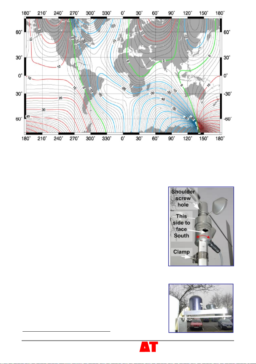
Typical map of magnetic declination for year 2000
(reproduced courtesy of NOAA)
From this map you can see the magnetic variation around the world can be quite large.
Magnetic north also drifts over time, so it is best to refer wind direction to true north.
Star Method: Find the North Star or the Southern Cross.
Whichever method you use, establish where True North intersects the horizon.
Orient the wind vane
1. Ensure that the locking shoulder screw #23
1
is in
place on the hub. The wind vane cannot rotate and,
if read, the sensor should indicate 180 degrees, i.e.
south.
2. Using the spanner provided, loosen the clamp
holding the O34B to the cross arm,
3. Rotate the housing body until the counterweight and
the black arrow on the housing actually point to true
south (and the wind vane tail points to true north).
4. Tighten the clamp and remove the shoulder screw to
release the wind vane and allow it to rotate freely.
6 Level the light sensor
Adjust the tripod of screws supporting the light sensor to
centre the bubble level, using the 2.5 mm hexagonal
socket wrench provided .
Note: You may need to stand on steps or a box or use a
mirror to see the bubble level.
1
See the D-034-CA Technical Manual on the Software and Manuals CD

Page 6 © 2018 Delta-T Devices Ltd
7Install and Start GP1 Software
Install and start the GP1 software DeltaLINK on your PC as
instructed in the GP1 Quick Start Guide and connect to the Weather Station GP1
logger using the GP1-RS232 cable provided.
8 Examine the GP1 Program
1. Select the Program window. Factory installed weather stations will have the
WS-GP1 Weather Station Program pre-installed as shown
2. If missing, to reinstall this program Click Change on the Program window and
select File, New Program, WS-GP1 Weather Station Program and click OK.
3. Click on and examine the Air, Wind Sun and Rain sensor tabs.
4. Examine the context sensitive online Help for each tab.
5. Note the default 1 hour Recording Rate in the Main tab and the choice of faster
sampling rates for individual sensors in the Sensor tabs, and modify them as
required.
6. Note the various recording options such
as Average, Maximum, Time of
maximum and so on, and click the
check boxes as required.
7. Note the choice of units for wind run
and radiation integral.
8. Make any change you deem necessary
to the program and click Apply to install
it to the logger.
For definitions e.g. for the various wind
rose options: see the online Help.
Page 7 © 2018 Delta-T Devices Ltd
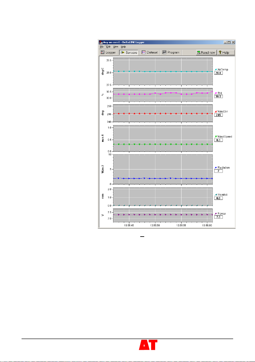
9Check sensors & start logging
1. Select the Sensors
window and click the
Read now button. The
sensor readings will
continually refresh on a
scrolling time graph.
2. Observe the sensor
reading display in the
scrolling charts and value
panels.
3. Check the wind vane
reads 360 degrees at
north and 180 at south.
4. Spin the anemometer and
blow on the radiation
shield and check the
readings look plausible.
5. Illuminate the light sensor
then cover it, and check
the readings seem
plausible.
6. Pour water into the rain
gauge funnel to simulate
rainfall.
7. Click the Cancel button
when finished.
8. Select the Logger
window and click Start to
commence logging.
For help diagnosing sensor behaviour - from the Help menu (Alt H) select Document
Library (Alt D), and then WS-GP1 to display the Weather Station Document Library
and refer to the individual sensor technical manuals.
Weather Records
10 Collect and Save Logged Data
1. Select the Dataset window. All stored data in the logger will be retrieved and
displayed on the screen (it may take a few seconds to download the data).
Click Refresh if required.
2. Select File, Save to save the data to a dataset file.
3. Select File, Open to open and view a previously saved dataset file.
4. To save a dataset file as a ASCII file for importing into other programs, open the file
in DeltaLINK, and select File, Save As… selecting the appropriate file type to save.
Page 8 © 2018 Delta-T Devices Ltd
11 View Weather
Display Options in Dataset
View
Right-click on the timescales axis to
select from the preset timescale options.
Left click and drag on a chart to mark out
a zoom region. Then right-click to zoom.
Right click on the value axis to restore
the default zoom.
Left click and drag top and bottom chart
borders then click to resize the chart
Right click on the chart region to pop up
a menu of display options including Hide,
Show all Charts and Details options
See also the online Help
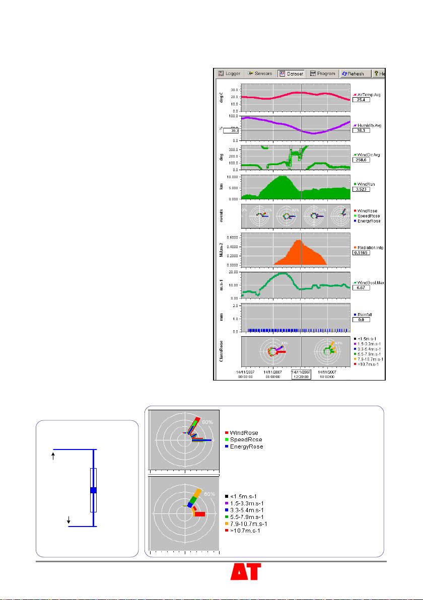
Example Dataset
From the Help menu (Alt H) select
Document Library (Alt D), and then WS-
GP1 to display the Weather Station
Document Library
Double click on the file “Example WS-
GP1 Weather Station data.dt6 to
display a typical record.
Examine the display options as outlined
above.
Average
Maximum
+1 standard
deviation
Minimum
Key to statistical
symbols
Time of
maximum
Time of
minimum
% of time wind was from each direction:
% of windrun from each direction
% of wind energy from each direction
Class Rose: % of time speed was in each
Beaufort scale range
1
2
4
3
5
6 and greater
-1 standard
deviation
Note –Statistical symbols
are only available if
selected in the program

Page 9 © 2018 Delta-T Devices Ltd
Further processing your weather data
Dataset Import Wizard helps you seamlessly import data into MS Excel
spreadsheets. Multiple dataset files may be imported and the data interleaved.
See GP1 Quick Start Guide for instructions on using the Dataset Import Wizard.
Once your data is in Excel, many third-party Excel add-ins are available to help you
process your database.
Note: at the time of writing this document Excel can only graph up to 32000 lines of
data.
Moving the station
For its protection, remove the wind sensor vane before moving the weather station.
The blue box is NOT drop proof, so carry it carefully. Do not ship it by commercial
carrier without further protective packing.
Battery Life
Replace the battery before
the battery voltage indicator
drops below 5.5V.
At 1 reading/ minute on all
sensors a 9V Alkaline battery
may last 90 days.
To increase this, reduce the
reading frequency, and/or use
a lithium battery or external
lead acid battery.
The RH sensor dominates the
current consumption -
reducing RH sensor readings
to once every 5 minutes will
more than double battery life.
You might expect an external 10 Ahr lead acid battery to last longest, but internal self
discharge may limit this to 12 months at 25C or only 3 months at 40C. So unless it is
periodically recharged –for example by a solar panel - a lead acid battery may not
outlast a Lithium battery with its longer shelf life.
Note: When retrieving data, keep an eye on your logger battery. Its status is reported
by the logger software, and you can also log it along with the sensor readings. The
voltage reported is that presented to the sensors, and is slightly less than that at the
battery terminals.
BatteryLife Estimator
0
200
400
600
800
010 20 30 40 50 60 70 80 90 100
Frequency of RH readings (minutes)
Life (days)
9V Lithium
9V alkaline

Page 10 © 2018 Delta-T Devices Ltd
Specifications
Specification Range/Notes
Logger GP1
± (0.3mV+0.01% reading)
typical at 20C
± (1.63mV+0.05% reading) max over -20°C to + 60°C
± 0.07°C typical at 20°C
± 0.13°C max. (-20°C to +60°C)
Readings > 600,000
Logging frequency 1s to 24 hr
Data collection To PC or Pocket PC
Logging status Flashing LED
Environmental -20°C to +60°C, IP67
Wind speed
± 0.1m.s-1 up to 10m.s-1 (22.7 mph)
± 1.1% of reading
over 10m.s-1 (22.7 mph)
Range
0 to 75m.s-1 (0 to 167 mph)
Starting threshold
0.4 m.s-1 (0.9 mph)
Wind direction
Accuracy
± 4
0 to 356 electrical
0 to 360 mechanical
Starting threshold
0.4 m.s-1 (0.9 mph)
Damping ratio .25
Resolution
< 0.5
Temperature
Accuracy at 25°C
± 0.2°C sensor and logger
IP65
0.5 °C
at 3 m.s-1
1.0 °C
at 2 m.s-1
2.0 °C
at 1 m.s-1
RH ± 2% RH 5 to 95% RH
± 2.5% RH < 5% and > 95% RH
Envronmental -20 to 80°C, 0-100%RH IP65
Response time < 10s
90% of scale for a step change from
11% to 75% RH
Rainfall Sensitivity 0.2mm per tip
up to 360 mm.hr-1
Solar Radiation
Calibration Uncertainty ± 5%
Spectral Range 360 to 1120 nm response exceeds 10% of maximum
Cosine response ± 5%
75zenith angle
Drift <2% per year
Environmental -40 to 70°C, 0 to100%RH can be immersed up to 30m in water
Accuracy at 25°C
Accuracy analog
Temperature accuracy
for 10K thermistor (at -20 to + 60C)
Accuracy
Range
Radiation Shield error

Page 11 © 2018 Delta-T Devices Ltd
Sensor Wiring
Service & Recalibration
Before returning parts please contact Delta-T or your local agent for instructions.
Wind speed and direction D-034B-CA
Recalibrate: every year. Service: 6-12
months: look & listen to see if the vane and
cups are running freely, are undamaged, and
are not loose. 12-24 months: replace
anemometer bearings. 24-36 months:
complete factory overhaul of sensor.
Most parts are replaceable in the field.
Note: the Windvane, though connected to
GP1 terminal Temp3, is actually read as a
voltage output sensor (0-2.5V equals 0-360
degrees). The internal circuit differs from the
standard MetOne O34B, see panel at right.
See also D-034B-CA Technical Manual on the Delta-T Software and Manuals CD.
10K
10K
5V (ref)
GND
Temp3 (IN)
Temp3 (GND)
green
yellow
white
1M
Windvane circuit schematic
1K

Rain gauge RG2
Can be recalibrated in the field.
See also the RG2+WS-CA Technical Manual on the Software and Manuals CD
Light sensor D-PYRPA-CA
Typical drift 1% per year. Recalibrate every 2 years. Keep it clean and level.
Manufacture’s Warranty: 1 year parts and labour.
See also the D-PYR-PA Technical Manual on the Software and Manuals CD
RH & air temp sensor RHT3nl-CA
Typical drift -1.5 to -2% in the first year, -1% in the second year and -0.5% in the third.
No adjustment of the RH or temperature element is possible. Inaccurate sensors must
be replaced with new module which can be plugged in the field. Replace every two
years in clean atmospheric conditions or every year if the atmosphere is polluted.
Replacing the RH Sensor
Note: the RHT3nl uses a 10K Betatherm 10K3A1B thermistor and a 6 plate radiation
shield but is otherwise similar to the RHT2nl sensor.
See also the RHT3nl-CA Technical Manual on the Software and Manuals CD.
Notices
This product uses software code. It should not be used in safety-critical applications or where
consequential loss may occur. It is the responsibility of the user to ensure appropriate
safeguards are in place for regularly monitoring and checking the equipment.
In no event shall Delta-T’s liability exceed the selling price of the product. Delta-T is not liable for
indirect, incidental or consequential damages in connection with the use of equipment, including
but not limited to: data loss, vegetation loss, loss of energy or water, cost of substitute equipment
or services, property damage, or personal injury that results from installer’s negligence. The
customer agrees to the limitations and exclusions of liability by purchase or use of this product.
See also the GP1 Product Usage.pdf in the online Document Library folder.
The WS-GP1 Weather Station is CE compliant, See WS-GP1 EC Certificate.pdf in the online
Document Library folder.
Delta-T Devices Ltd
130 Low Road, Burwell
Cambridge CB25 0EJ
UK
Table of contents
Popular Weather Station manuals by other brands


Oregon Scientific
Oregon Scientific BAR808HG user manual

Bresser
Bresser 7002520 000 000 instruction manual

Steinberg Systems
Steinberg Systems SBS-WS-600 user manual

La Crosse Technology
La Crosse Technology WEATHER DIRECT WA-1242U owner's manual

La Crosse Technology
La Crosse Technology 308-141WBV2 instruction manual

Spectrum Technologies
Spectrum Technologies WatchDog 3000 Series product manual