Delta-T SOL2-UM-2 User manual

SOLAR POWER SUPPLY
for Delta-T logging systems
Type SOL2
USER MANUAL
SOL2-UM-2

SOL2
SOL2-UM-2 Oct 2001
Page 2
CONTENTS
INTRODUCTION AND DESCRIPTION 3
UNPACKING AND INSTALLATION 4
WIRING AND COMMISSIONING 5
MAINTENANCE 5
REPAIRS, SERVICE & SPARES 6
ADDITIONAL INFORMATION at end
Copyright
Copyright ©2001 Delta-T Devices Ltd., 128 Low Road, Burwell, Cambridge,
CB5 OEJ, England. All rights reserved. Under the copyright laws this book
may not be copied, in whole or in part, without the written consent of Delta-T
Devices Ltd. Under the law, copying includes translation into another language.
Delta-T Devices Ltd
128 Low Road, Burwell,
Cambridge CB5 OEJ, England
Telephone : (01638) 742922
Fax : (01638) 743155
Web site : www.delta-t.co.uk

SOL2
INTRODUCTION AND DESCRIPTION
This Manual describes the general specification, installation and maintenance of the SOL2 Solar
Power Supply. Detailed information on the system components can be found at the end of this
Manual.
The system may be used with either DL2e or DL3000 data loggers. This Manual should be read
in conjunction with the User Manual for the data logger used in the system, or with the
Application Manual, if supplied with the system.
The Solar Power Supply type SOL2 comprises two main components:
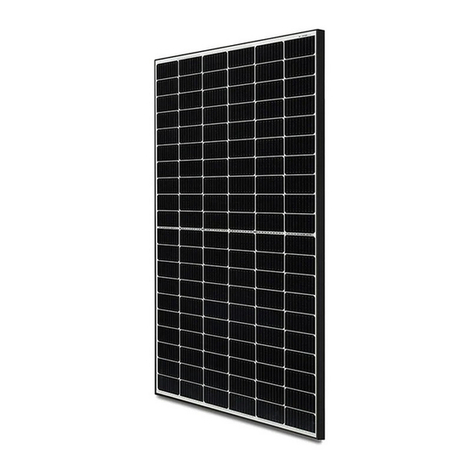
A. Photovoltaic cell, Siemens type SM10. This will provide approximately 0.5A at 12-
15VDC when exposed to solar radiation levels of 1000 W/m2.
B. System Regulator, Solsum type 6.6x. This monitors the photovoltaic cell and battery
voltage and controls the battery charging rate. (Inside weatherproof enclosure and
desiccant bag).
Additionally a battery type LBAT2 will be supplied to match the solar system:
C. High capacity, 38Ah, 12v, deep discharge battery. (Can be stored inside a lockable,
weatherproof box type BTBOX2)
Additionally a 2M length of white, 1.5mm² twin core cable is to be connected to the battery and
a 1M length of black 0.75mm² twin core cable is to be connected to the data logger.
Logger Cable,
enclosure and
terminal block
Battery Cable with
battery lugs
System regulator,
Solsum type 6.6x
(lid removed)
Photovoltaic cell,
Siemans type
SM10
SOL2-UM-2 Oct 2001
Page 3

SOL2
UNPACKING AND INSTALLATION
Unpacking
The system has been tested and checked at the factory and is ready for installation.
Immediately on receipt of the consignment, check it for possible damage in transit. Unpack the
consignment carefully and check all the items in the packing list. Do not dispose of any packing
material until any suspected shortage has been established beyond all possible doubt.
Please contact your agent or Delta-T Devices if damage has occurred, or if any parts on the
packing list are missing.
Installation
A crossarm and clamp type SOL2B are normally provided for attachment to the vertical pole of
the standard weather station mast.
The panel assembly should be positioned as shown in the picture. The battery should placed
beneath the solar panel as shown to give natural protection from solar radiation. This may have
been supplied with a lockable battery box type BTBOX2 to enable easier protection and greater
security.
The orientation of the solar panel is determined by the geographical location of the system.
Basically the panel should face directly towards the position of the mid-day sun, with as little
amount of shade as possible. It is normally good practice to mount the panel as close to the
ground as possible in order to reduce the effects of strong wind loads.
SOL2-UM-2 Oct 2001
Page 4

SOL2
SOL2-UM-2 Oct 2001
Page 5
WIRING AND COMMISSIONING
The photovoltaic cell is pre-wired to the system regulator before shipment to prevent reverse
polarity interconnection
Two, twin core cables are pre-attached to the system regulator.
A. Battery cable. Identified by its white sheath and battery lugs attached to each core.
Brown core must be connected to the POSITIVE battery terminal.
Blue core must be connected to the NEGATIVE battery terminal.
B. Load cable.
BROWN core should be connected the positive side of the load distribution block for your
application. This is the place where all your loads are brought to a central point. For most
applications this will be the digital connection block of the logger. For exact connection refer to
your logger or application manual
BLUE core should be connected the negative side of the load distribution block for your
application. This is the place where all your loads are brought to a central point. For most
applications this will be the digital connection block of the logger. For exact connection refer to
your logger or application manual.
NOTE THAT CARE MUST BE TAKEN TO ENSURE THAT BOTH THE BATTERY
CABLE AND LOAD CABLE ARE CORRECTLY CONNECTED. INCORRECT
CONNECTION MAY DAMAGE THE EQUIPMENT.
Before connecting either the battery or load, cover the solar panel to minimise the voltage
generated.
First connect the Battery cable to your battery. Then connect the Power Cable to the load
distribution block ONLY after thoroughly checking that your load wiring is correct
Specifications and general notes for the Photovoltaic cell System Regulator are attached, but all
the necessary modifications for your application have already been made. A 6.3A fuse is
installed on the System Regulator terminal board, to protect against excessive load currents.
MAINTENANCE
The solar panel and regulator are sealed against the environment. Maintenance is limited to
regular washing of the solar panel surface with fresh water.
The battery supplied with this system is of the sealed, lead acid type and requires no topping up
of electrolyte. The battery terminals should be greased and kept free from dust and moisture.
Some protection is achieved by placing the battery beneath the solar panel. Th battery can be
placed in a vented box if further protection is required.

SOL2
SOL2-UM-2 Oct 2001
Page 6
GUARANTEE, REPAIRS AND SPARES
Our Conditions of Sale ref: COND/91/11 set out Delta-T's legal obligations on these matters. For
your information the following paragraphs summarise Delta-T's position but reference should
always be made to our Conditions of Sale which prevail over the following explanation.
Instruments supplied by Delta-T are guaranteed for one year against defects in manufacture or
materials used. The guarantee does not cover damage through misuse or inexpert servicing, or
other circumstances beyond our control.
For the UK this means that no charges are made for labour, materials or return carriage for
guarantee repairs.
For other countries, the guarantee covers free exchange of faulty parts during the guarantee
period.
Alternatively, if the equipment is returned to us for guarantee repair, we make no charge for
labour or materials but we do charge for carriage and UK. customs clearance.
We strongly prefer to have such repairs discussed with us first, and if we agree that the
equipment does need to be returned, we may at our discretion waive these charges.
SERVICE AND SPARES
We recognise that some users of our instruments may not have easy access to technically
specialised backup.
Spare parts for our own repairable instruments can be supplied from our works. These can
normally be despatched within 1 working day of receiving an order.
Spare parts and accessories for sensors not manufactured by Delta T, but supplied by us
individually or as part of the weather station or other system, may be obtained from the original
manufacturer. We will endeavour to obtain parts if requested, but a certain amount of additional
delay is inevitable.
Should it prove necessary, instruments may be returned to our works for servicing. We normally
expect to complete repairs of our own instruments within 2 days of receiving the equipment.
Other manufacturers' sensors supplied by us and returned for servicing will take longer. They
will have to be returned to the original manufacture for servicing, and may be subject to
additional delays of two to four weeks.
Users in countries that have a Delta-T Agent or Technical Representative should contact them in
the first instance.
Table of contents
